Beginning by the principle
Take the extension cord and cut the cable shortly before arriving at the end where the male connector is connected. Cut the cable with the scissors with care not cutting any of wiers that are in the interior. Now cut each one of these wires (except the one th 636g64g at does not have insulator that you can cut it directly) removing little insulation from the ends of the wires so you have bare wire.
Verify that it has at least 7 wires without counting the one that is bare. If you have a dual-shock compatible pad make sure it has 8 wires.
We are going to find out to what hole of the female connector is connected to which small wire. Take the female connector of the cable and put the pin in each one of the holes to make contact and, using the multi-meter on resistant setting, write down to what hole corresponds each wire of the other end. So stick the pin on hole 1 then touch the ends of the wires until you find the one that matches the corresponding hole. Don't be to worried if you don't find a wire for each hole there are only 7 or 8 wires and 9 holes.
Well, we now have written on the paper the relation of the holes from the 1 to the 9 and to what cable color in the other end corresponds to each one of them. Keep this paper in a safe place that you will need it later.
|
Tin-plating DB-25 connectors Take DB-25 connector and tin-plate the ends where we are going to make the connections, that are 2, 3, 4, 5, 6, 7, 8, 9, 10, 12, 18 and 19. Look to the attached figure considering that the part that is seen in drawing is the part where we are going to solder. The pins where we are going to make connections are in red. The pins in blue are those that we will use if we connect a second pad. |
DB-25 CONNECTOR |
Soldering the diodes Now for the delicate part. Take the 5 diodes and it
cuts the ends that are on the side opposition to the mark (what marks? see the
figure alongside see the correspondence with the drawing in the picture and the
real diode) leaving more or less half centimeter
(like in the previous image). Now we take the soldering iron and tin-plate the
end of each diode taking care that you do not taking too long doing it or you
can 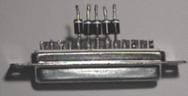 damage the diode by the heat.
![]()
Next we will take the DB-25 connector with the corresponding tin-plated ends (you did do in the previous section) and solder the short ends of each one of the diodes in ends 5, 6, 7, 8 and 9 of the DB-25 connector. Remember that you must weld the 5 diodes in the correct direction. It should look like image alongside.
And finally, soldering wires
And we are now in the last of the mechanical part. Going by the diagram of the circuit on the paper where you wrote down the corresponding wires of your extension to the holes of the female connector. Solder the corresponding pin to each of the wires from the extension.
The wire that corresponds to hole 5 of the connector you have it to weld to the other ends of the 5 diodes. Solder the wire to the end of the central diode and solder the 5 diodes together as it appears in the circuit. using a spare piece of wire.If you pay attention, hole 6 of the female connector must go connected to pins 18 and 19 of connector DB-25. Solder the corresponding wire of the extension to any of the two pins and connect the two pins together.
Only if you want to use the a Force Feedback pad...
Take a cable of two threads of 0.5m of different colors (ei. red and black) and it connect the red wire to the wire of the extension that corresponds to hole 7. The other wire (the black) you solder to pin 18 or 19 or where it connected the wire that corresponds of hole 6.
The other end of this cable we connected to the power supply having TAKEN CARE to connect the black to the negative (-) and the red to the positive (+). Make sure that the voltage is 9v using a milti-meter. And it is ready.
That's all. Review all
the connections before connecting the DB-25 connector 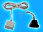 to the parallel port!!
Drawings of the final result
WITHOUT FORCE FEEDBACK 
WITH FORCE FEEDBACK 
|