Thermal/Structural Analysis of a Roots type Supercharger.
In this exercise, we will perform a thermal/structural
analysis of a Roots type automobile supercharger.
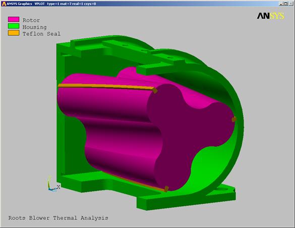
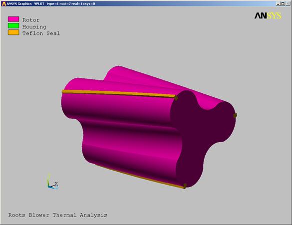
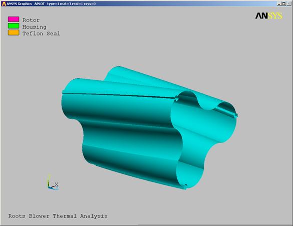
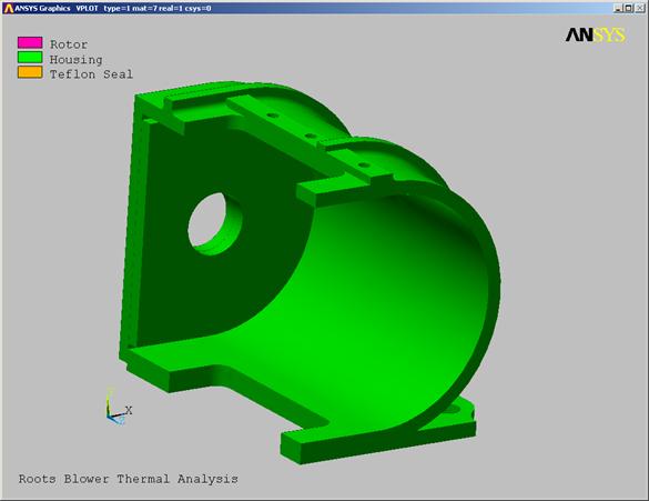
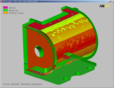
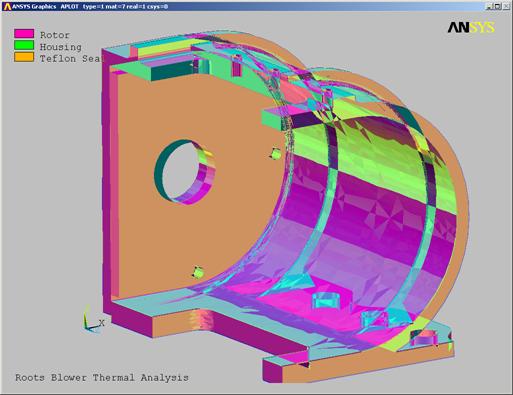
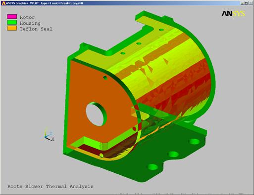
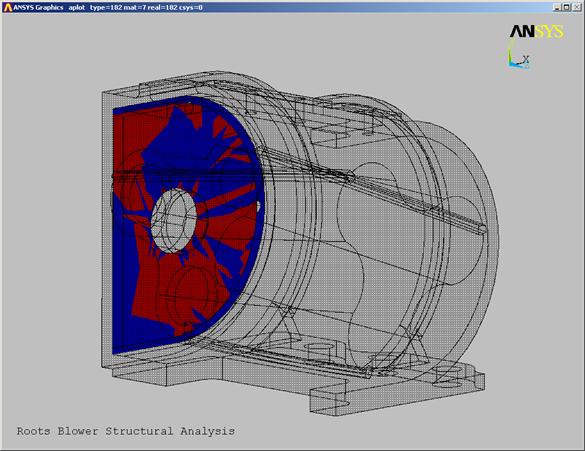
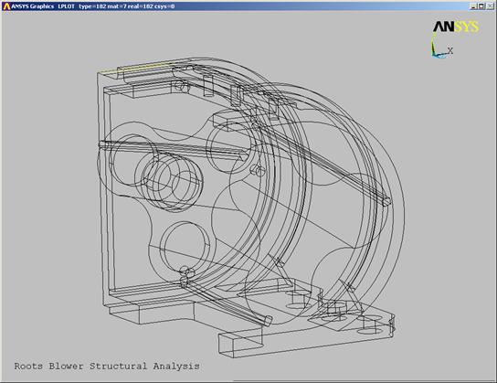
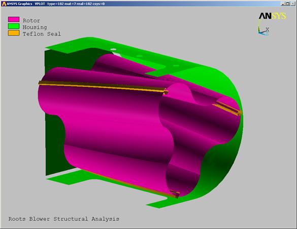
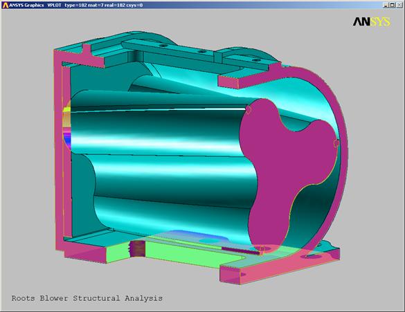
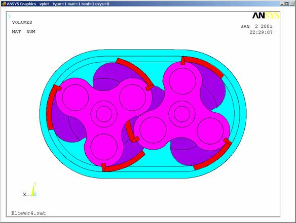
The Roots type supercharger shown below is used to boost
the intake pressure of an internal combustion engine by approximately 12-15
PSI, drastically improving the performance of the engine. The device consists of two rotor assemblies
turning in opposite directions. The air
is pushed around the outside of the rotors and out the bottom. Air can't leak back up through the rotors due
to the close clearances between the rotors and the case. The outer surface of each rotor lobe contains
a Teflon seal strip to prevent leakage. In order to reduce pulsing of the pressure, the lobes are often twisted
along the rotational axis, or helically, as shown below.
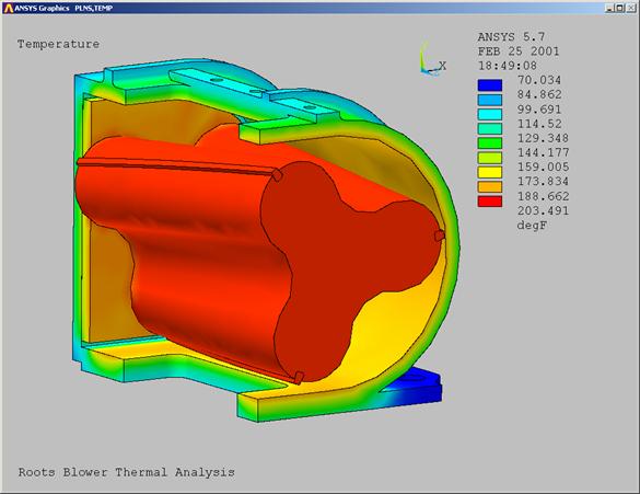
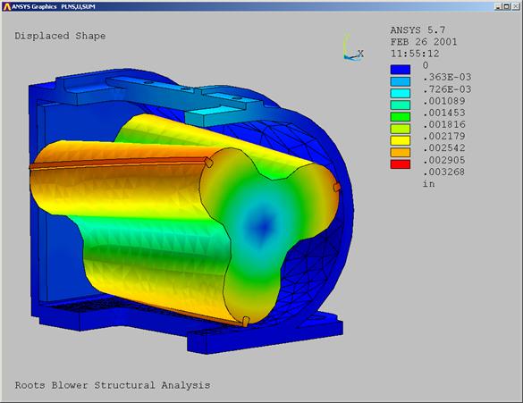
The purpose of this analysis is to determine the clearance or interference of
the rotor lobe seals and the case. Minimizing this clearance under start-up and operating temperatures is
crucial to supercharger performance. We
will do this by performing a steady state thermal analysis of the supercharger
followed by a structural contact analysis.
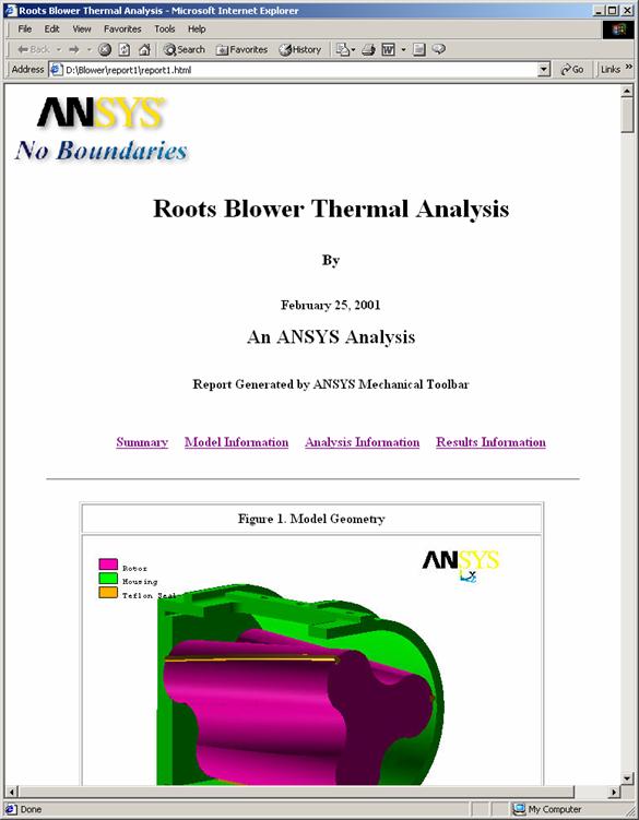
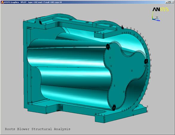
Symmetry will be used to model only half of one rotor and
1/4 of the case. The geometry will be
imported into ANSYS Professional as an existing ANSYS database to save you
time.
A steady state thermal analysis will be performed. Thermal boundary conditions will consist of
an elevated internal temperature convection load and an ambient temperature
convection load on the exterior.
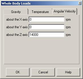
A structural analysis will follow the thermal. Loading will be thermal loads from the
previous heat transfer analysis, internal pressures, and a rotational velocity
on the rotor. Contact elements will be
used to seat the Teflon seals in the rotor lobe slots, and to determine the
clearance or rub between the rotor seals and the case.
Summary of Steps:
Launch
ANSYS/Professional:
Launch
ANSYS using your start menu.
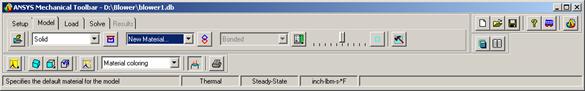
Mechanical
Toolbar Setup:
Toolbar
settings.
Model:
Import
Model.
Plotting
Controls.
Material
Properties:
Rotor
Material Properties.
Housing
Material Properties.
Seal
Material Properties.
Contact
Definition:
Define
Contact Pairs.
Meshing:
Mesh
Model.
Thermal
Loads Application:
Rotor
Convection Surface Selection.
Rotor
Convection Load Application.
Internal
Housing Surface Selection.
Internal
Housing Convection Load Application.
External
Housing Surface Selection.
External
Housing Convection Load Application.
Thermal
Solution:
Save
Database.
Solve
Thermal
Results Post Processing:
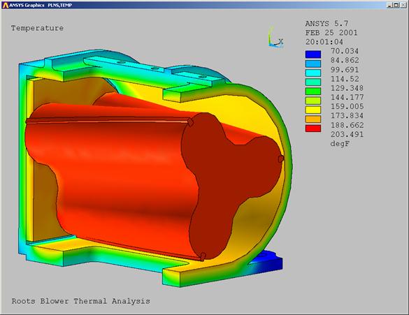
Temperature
Plots:
Structural
Analysis.
Structural
Model Setup.
Structural
Contact Element Definition.
Add
Contact.
Structural
Loads and BC's:
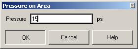
Pressure
Loads.
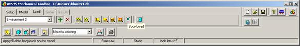
Body
Loads.
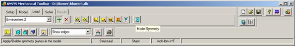
Symmetry BC's.
Structural
Model Solution:
Solve
Post
Processing:
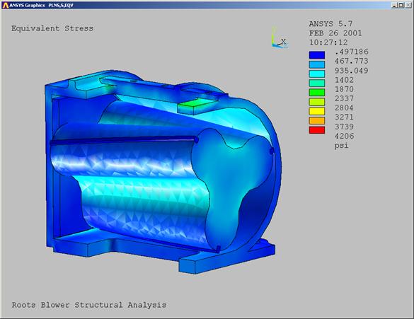
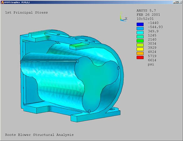
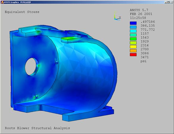
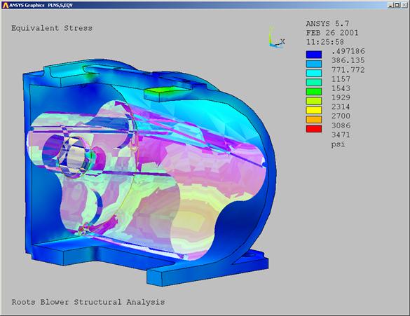
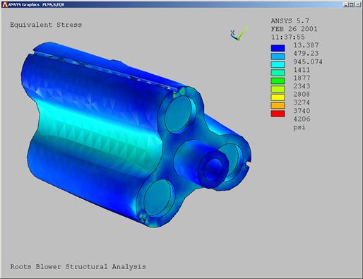
Stress
Plots.
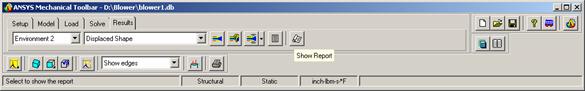
Structural
Analysis Report Generation.
Conclusions:
Step-by-step Instructions:
Before beginning this problem, create a separate folder
on your computer for this job and copy the ANSYS database blower.db to
this folder from the CD.
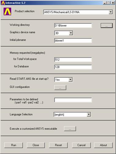
Launch
ANSYS/Professional
Launch ANSYS using your
start menu
A. Browse to select the working
directory you just created for this job.
B. Enter a job name (blower1). All ANSYS files created for this problem will
have a filename of blower1 followed by a unique extension.
C. Change the workspace and
database sizes for this job to be 512 and 128 respectively.
D. Click RUN to start
the ANSYS GUI.
1.1.B08D0C9EA79F9BACE118C8200AA004BA90B02000000080000000E0000005F005200650066003400390039003300390032003300310037000000
1.1.B08D0C9EA79F9BACE118C8200AA004BA90B02000000080000000E0000005F005200650066003400390039003300390032003300310037000000
1.1.B08D0C9EA79F9BACE118C8200AA004BA90B02000000080000000E0000005F005200650066003400390039003300390032003300310037000000
1.1.B08D0C9EA79F9BACE118C8200AA004BA90B02000000080000000E0000005F005200650066003400390039003300390032003300310037000000
|

1.1.A08D0C9EA79F9BACE118C8200AA004BA90B02000000080000000E0000005F005200650066003400390039003300390032003100320036000000
1.1.A08D0C9EA79F9BACE118C8200AA004BA90B02000000080000000E0000005F005200650066003400390039003300390032003100320036000000
1.1.A08D0C9EA79F9BACE118C8200AA004BA90B02000000080000000E0000005F005200650066003400390039003300390032003100320036000000
1.1.A08D0C9EA79F9BACE118C8200AA004BA90B02000000080000000E0000005F005200650066003400390039003300390032003100320036000000
|

1.1.D08D0C9EA79F9BACE118C8200AA004BA90B02000000080000000E0000005F005200650066003400390039003300390032003300320039000000
1.1.D08D0C9EA79F9BACE118C8200AA004BA90B02000000080000000E0000005F005200650066003400390039003300390032003300320039000000
1.1.D08D0C9EA79F9BACE118C8200AA004BA90B02000000080000000E0000005F005200650066003400390039003300390032003300320039000000
1.1.D08D0C9EA79F9BACE118C8200AA004BA90B02000000080000000E0000005F005200650066003400390039003300390032003300320039000000
|

1.1.C08D0C9EA79F9BACE118C8200AA004BA90B02000000080000000E0000005F005200650066003400390039003300390032003300320033000000
1.1.C08D0C9EA79F9BACE118C8200AA004BA90B02000000080000000E0000005F005200650066003400390039003300390032003300320033000000
1.1.C08D0C9EA79F9BACE118C8200AA004BA90B02000000080000000E0000005F005200650066003400390039003300390032003300320033000000
1.1.C08D0C9EA79F9BACE118C8200AA004BA90B02000000080000000E0000005F005200650066003400390039003300390032003300320033000000
|

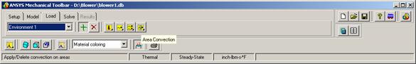
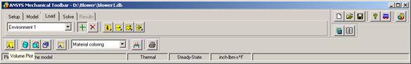
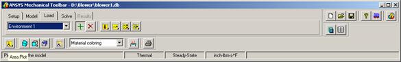
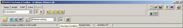
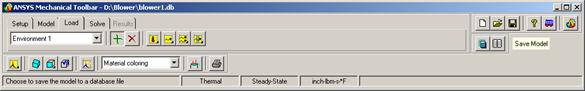
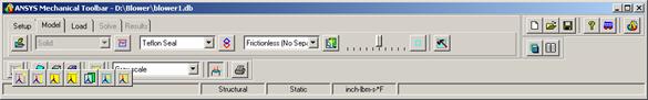
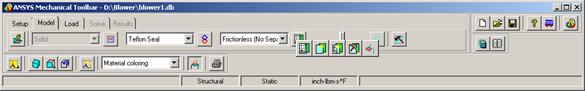
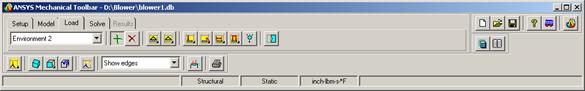
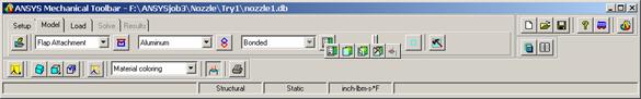
Mechanical Toolbar Setup
Toolbar settings.
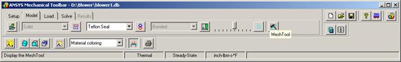
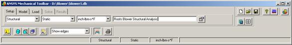
A. Change
Structural to Thermal
B. Change
the units to inch-lbm-s-F
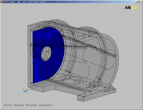
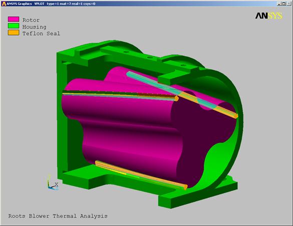
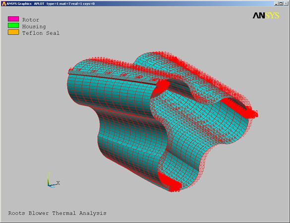
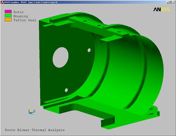
C. Change the title to Roots
Blower Thermal Analysis
2.1.C08D0C9EA79F9BACE118C8200AA004BA90B02000000080000000E0000005F005200650066003400390039003300390032003700380039000000
2.1.C08D0C9EA79F9BACE118C8200AA004BA90B02000000080000000E0000005F005200650066003400390039003300390032003700380039000000
2.1.C08D0C9EA79F9BACE118C8200AA004BA90B02000000080000000E0000005F005200650066003400390039003300390032003700380039000000
2.1.C08D0C9EA79F9BACE118C8200AA004BA90B02000000080000000E0000005F005200650066003400390039003300390032003700380039000000
|
2.1.B08D0C9EA79F9BACE118C8200AA004BA90B02000000080000000E0000005F005200650066003500300037003100350036003100350035000000
2.1.A08D0C9EA79F9BACE118C8200AA004BA90B02000000080000000E0000005F005200650066003400390039003300390032003700380034000000
2.1.B08D0C9EA79F9BACE118C8200AA004BA90B02000000080000000E0000005F005200650066003500300037003100350036003100350035000000
2.1.A08D0C9EA79F9BACE118C8200AA004BA90B02000000080000000E0000005F005200650066003400390039003300390032003700380034000000
|
2.1.A08D0C9EA79F9BACE118C8200AA004BA90B02000000080000000E0000005F005200650066003500300037003100350034003400350034000000
2.1.A08D0C9EA79F9BACE118C8200AA004BA90B02000000080000000E0000005F005200650066003400390039003300390032003700380034000000
2.1.A08D0C9EA79F9BACE118C8200AA004BA90B02000000080000000E0000005F005200650066003500300037003100350034003400350034000000
2.1.A08D0C9EA79F9BACE118C8200AA004BA90B02000000080000000E0000005F005200650066003400390039003300390032003700380034000000
|
Model
Import Model.
A. Pick the Model tab in the
Mechanical Toolbar (MTB).
3.1.A08D0C9EA79F9BACE118C8200AA004BA90B02000000080000000E0000005F005200650066003400390039003300390034003100340031000000 23323j921x
3.1.A08D0C9EA79F9BACE118C8200AA004BA90B02000000080000000E0000005F005200650066003400390039003300390034003100340031000000 23323j921x
3.1.A08D0C9EA79F9BACE118C8200AA004BA90B02000000080000000E0000005F005200650066003400390039003300390034003100340031000000 23323j921x
3.1.A08D0C9EA79F9BACE118C8200AA004BA90B02000000080000000E0000005F005200650066003400390039003300390034003100340031000000 23323j921x
|
B. Next, we will import the
blower geometry from an ANSYS database. (ANSYS can import a variety of geometry formats as well). Pick the Import Geometry button.
3.1.B08D0C9EA79F9BACE118C8200AA004BA90B02000000080000000E0000005F005200650066003400390039003300390034003100340037000000
3.1.B08D0C9EA79F9BACE118C8200AA004BA90B02000000080000000E0000005F005200650066003400390039003300390034003100340037000000
3.1.B08D0C9EA79F9BACE118C8200AA004BA90B02000000080000000E0000005F005200650066003400390039003300390034003100340037000000
3.1.B08D0C9EA79F9BACE118C8200AA004BA90B02000000080000000E0000005F005200650066003400390039003300390034003100340037000000
|
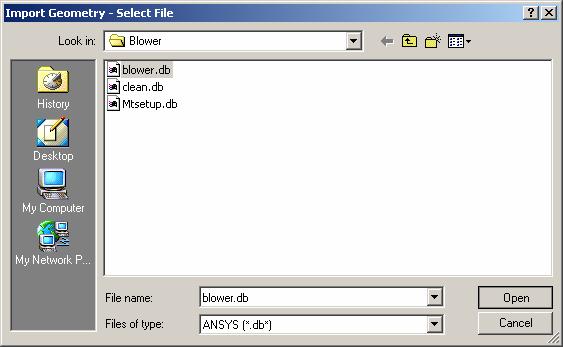
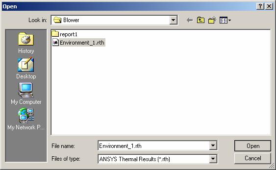
C. A dialog box will appear for
you to select the file to import. Change
the Files of type setting to ANSYS (*db)
D. Select blower.db
E. Open
3.1.C08D0C9EA79F9BACE118C8200AA004BA90B02000000080000000E0000005F005200650066003400390039003300390034003400330034000000
2.1.A08D0C9EA79F9BACE118C8200AA004BA90B02000000080000000E0000005F005200650066003400390039003300390032003700380034000000
3.1.C08D0C9EA79F9BACE118C8200AA004BA90B02000000080000000E0000005F005200650066003400390039003300390034003400330034000000
2.1.A08D0C9EA79F9BACE118C8200AA004BA90B02000000080000000E0000005F005200650066003400390039003300390032003700380034000000
|
3.1.D08D0C9EA79F9BACE118C8200AA004BA90B02000000080000000E0000005F005200650066003400390039003300390034003400340034000000
2.1.A08D0C9EA79F9BACE118C8200AA004BA90B02000000080000000E0000005F005200650066003400390039003300390032003700380034000000
3.1.D08D0C9EA79F9BACE118C8200AA004BA90B02000000080000000E0000005F005200650066003400390039003300390034003400340034000000
2.1.A08D0C9EA79F9BACE118C8200AA004BA90B02000000080000000E0000005F005200650066003400390039003300390032003700380034000000
|
3.1.E08D0C9EA79F9BACE118C8200AA004BA90B02000000080000000E0000005F005200650066003400390039003300390034003400340038000000
2.1.A08D0C9EA79F9BACE118C8200AA004BA90B02000000080000000E0000005F005200650066003400390039003300390032003700380034000000
3.1.E08D0C9EA79F9BACE118C8200AA004BA90B02000000080000000E0000005F005200650066003400390039003300390034003400340038000000
2.1.A08D0C9EA79F9BACE118C8200AA004BA90B02000000080000000E0000005F005200650066003400390039003300390032003700380034000000
|

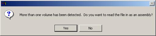
F. Ansys will ask if you want
to import this model as an assembly. Pick Yes.
3.1.F08D0C9EA79F9BACE118C8200AA004BA90B02000000080000000E0000005F005200650066003500300036003400380031003800390036000000
2.1.A08D0C9EA79F9BACE118C8200AA004BA90B02000000080000000E0000005F005200650066003400390039003300390032003700380034000000
3.1.F08D0C9EA79F9BACE118C8200AA004BA90B02000000080000000E0000005F005200650066003500300036003400380031003800390036000000
2.1.A08D0C9EA79F9BACE118C8200AA004BA90B02000000080000000E0000005F005200650066003400390039003300390032003700380034000000
|
Plotting Controls
A. Use the Pan/Zoom/Rotate
function to scrutinize all parts of the model. In the utility menu, pick PlotCtrls
B. Pan, Zoom,
Rotate. A view control window will
appear on your screen.
3.2.A08D0C9EA79F9BACE118C8200AA004BA90B02000000080000000E0000005F005200650066003400390038003000380030003200330035000000
3.2.A08D0C9EA79F9BACE118C8200AA004BA90B02000000080000000E0000005F005200650066003400390038003000380030003200330035000000
|
3.2.B08D0C9EA79F9BACE118C8200AA004BA90B02000000080000000E0000005F005200650066003400390038003000380030003200340032000000
3.2.B08D0C9EA79F9BACE118C8200AA004BA90B02000000080000000E0000005F005200650066003400390038003000380030003200340032000000
|
These buttons will orient your display to predefined
view perspectives.
These buttons will orient your display to predefined
view perspectives.
|
Zoom by picking a center point and the edge of your
window.
Zoom by picking a center point and the edge of your
window.
|
Zoom by picking two diagonal corners of your
window.
Zoom by picking two diagonal corners of your
window.
|
Arrows will pan your model in the direction of the
arrow. The distance your model is
moved can be controlled using the Rate slider below.
|
Rotate buttons will incrementally rotate your model
about the screen axis and direction shown on the button. The amount of rotation is also
controlled by the rate slider.
Rotate buttons will incrementally rotate your model
about the screen axis and direction shown on the button. The amount of rotation is also
controlled by the rate slider.
|
With dynamic Mode checked, you can use the mouse
buttons described at left to move the model or the lights used in light
source shading.
With dynamic Mode checked, you can use the mouse
buttons described at left to move the model or the lights used in light
source shading.
|
The Fit button will scale your model to fit in the
window.
The Fit button will scale your model to fit in the
window.
|
Pan Zoom Rotate Functions:
Activate dynamic mode. With this button checked, you can use dynamic viewing controls.
Use the left mouse button to pan the model.
With the middle button depressed, move up/down to zoom in/out, and left/right to rotate
about the screen Z-axis.
With the right button depressed, move up/down to rotate
about the screen X-axis, and left/right to rotate about the screen
Y-axis.
button to pan the model.
|
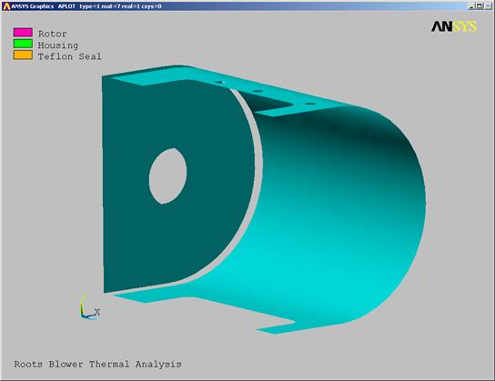
C. Use the Pan/Zoom/Rotate
controls to orient the model to a view similar to the one below:
3.2.C08D0C9EA79F9BACE118C8200AA004BA90B02000000080000000E0000005F005200650066003500300037003100350035003800340036000000
3.2.C08D0C9EA79F9BACE118C8200AA004BA90B02000000080000000E0000005F005200650066003500300037003100350035003800340036000000
|
Material Properties:
We will use three different materials for this
model. The rotor is made of
aluminum. The case and bearing plate are
made of cast iron. The seal strips at
the OD of the rotor are made of Teflon.
During the structural analysis, we will assign a
rotational velocity to the model. Since
centrifugal loading in ANSYS cannot be applied selectively, we will assign a
zero density to the case material to prevent it from "spinning".
Rotor Material Properties.
A. In the material list, pick New
Material .

4.1.A08D0C9EA79F9BACE118C8200AA004BA90B02000000080000000E0000005F005200650066003500300037003100360032003200340035000000
008D0C9EA79F9BACE118C8200AA004BA90B02000000080000000E0000005F005200650066003400390039003500350032003300310034000000
4.1.A08D0C9EA79F9BACE118C8200AA004BA90B02000000080000000E0000005F005200650066003500300037003100360032003200340035000000
008D0C9EA79F9BACE118C8200AA004BA90B02000000080000000E0000005F005200650066003400390039003500350032003300310034000000
|

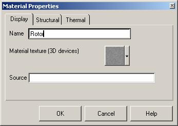
B. A dialog box will appear for
you to define this material. Enter a
name of Rotor.
C.
4.1.C08D0C9EA79F9BACE118C8200AA004BA90B02000000080000000E0000005F005200650066003500300037003100350037003900350034000000
4.1.B08D0C9EA79F9BACE118C8200AA004BA90B02000000080000000E0000005F005200650066003400390039003500350032003700320030000000
4.1.C08D0C9EA79F9BACE118C8200AA004BA90B02000000080000000E0000005F005200650066003500300037003100350037003900350034000000
4.1.B08D0C9EA79F9BACE118C8200AA004BA90B02000000080000000E0000005F005200650066003400390039003500350032003700320030000000
|

4.1.B08D0C9EA79F9BACE118C8200AA004BA90B02000000080000000E0000005F005200650066003400390039003500350032003700320030000000
4.1.B08D0C9EA79F9BACE118C8200AA004BA90B02000000080000000E0000005F005200650066003400390039003500350032003700320030000000
4.1.B08D0C9EA79F9BACE118C8200AA004BA90B02000000080000000E0000005F005200650066003400390039003500350032003700320030000000
4.1.B08D0C9EA79F9BACE118C8200AA004BA90B02000000080000000E0000005F005200650066003400390039003500350032003700320030000000
|

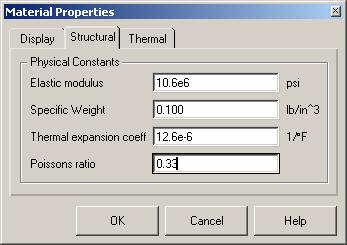
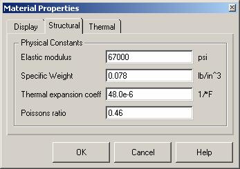
Pick the Structural tab.
D. For Elastic modulus,
enter: 10.6e6
E. For
Specific Weight, enter: 0.100.
F. For
Thermal expansion coeff, enter: 12.6e-6
G. For
Poissons ratio, enter: 0.33
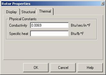
H.
Pick
the Thermal tab to define the thermal properties.
I. For
4.1.H08D0C9EA79F9BACE118C8200AA004BA90B02000000080000000E0000005F005200650066003500300037003100350038003400390039000000
4.1.B08D0C9EA79F9BACE118C8200AA004BA90B02000000080000000E0000005F005200650066003400390039003500350032003700320030000000
4.1.H08D0C9EA79F9BACE118C8200AA004BA90B02000000080000000E0000005F005200650066003500300037003100350038003400390039000000
4.1.B08D0C9EA79F9BACE118C8200AA004BA90B02000000080000000E0000005F005200650066003400390039003500350032003700320030000000
|

4.1.E08D0C9EA79F9BACE118C8200AA004BA90B02000000080000000E0000005F005200650066003500300037003100350038003400360032000000
4.1.B08D0C9EA79F9BACE118C8200AA004BA90B02000000080000000E0000005F005200650066003400390039003500350032003700320030000000
4.1.E08D0C9EA79F9BACE118C8200AA004BA90B02000000080000000E0000005F005200650066003500300037003100350038003400360032000000
4.1.B08D0C9EA79F9BACE118C8200AA004BA90B02000000080000000E0000005F005200650066003400390039003500350032003700320030000000
|

4.1.D08D0C9EA79F9BACE118C8200AA004BA90B02000000080000000E0000005F005200650066003500300037003100360032003100300031000000 23323j921x
4.1.B08D0C9EA79F9BACE118C8200AA004BA90B02000000080000000E0000005F005200650066003400390039003500350032003700320030000000
4.1.D08D0C9EA79F9BACE118C8200AA004BA90B02000000080000000E0000005F005200650066003500300037003100360032003100300031000000 23323j921x
4.1.B08D0C9EA79F9BACE118C8200AA004BA90B02000000080000000E0000005F005200650066003400390039003500350032003700320030000000
|

4.1.G08D0C9EA79F9BACE118C8200AA004BA90B02000000080000000E0000005F005200650066003500300037003100350038003400380037000000
4.1.B08D0C9EA79F9BACE118C8200AA004BA90B02000000080000000E0000005F005200650066003400390039003500350032003700320030000000
4.1.G08D0C9EA79F9BACE118C8200AA004BA90B02000000080000000E0000005F005200650066003500300037003100350038003400380037000000
4.1.B08D0C9EA79F9BACE118C8200AA004BA90B02000000080000000E0000005F005200650066003400390039003500350032003700320030000000
|

4.1.F08D0C9EA79F9BACE118C8200AA004BA90B02000000080000000E0000005F005200650066003500300037003100350038003400370036000000
4.1.B08D0C9EA79F9BACE118C8200AA004BA90B02000000080000000E0000005F005200650066003400390039003500350032003700320030000000
4.1.F08D0C9EA79F9BACE118C8200AA004BA90B02000000080000000E0000005F005200650066003500300037003100350038003400370036000000
4.1.B08D0C9EA79F9BACE118C8200AA004BA90B02000000080000000E0000005F005200650066003400390039003500350032003700320030000000
|
J. Specific
heat is not needed in a steady state analysis, so we will leave that field
blank. Pick OK.
4.1.I08D0C9EA79F9BACE118C8200AA004BA90B02000000080000000E0000005F005200650066003500300037003100350038003600370031000000 23323j921x
4.1.B08D0C9EA79F9BACE118C8200AA004BA90B02000000080000000E0000005F005200650066003400390039003500350032003700320030000000
4.1.I08D0C9EA79F9BACE118C8200AA004BA90B02000000080000000E0000005F005200650066003500300037003100350038003600370031000000 23323j921x
4.1.B08D0C9EA79F9BACE118C8200AA004BA90B02000000080000000E0000005F005200650066003400390039003500350032003700320030000000
|
4.1.J08D0C9EA79F9BACE118C8200AA004BA90B02000000080000000E0000005F005200650066003500300037003100350038003600370039000000
4.1.B08D0C9EA79F9BACE118C8200AA004BA90B02000000080000000E0000005F005200650066003400390039003500350032003700320030000000
4.1.J08D0C9EA79F9BACE118C8200AA004BA90B02000000080000000E0000005F005200650066003500300037003100350038003600370039000000
4.1.B08D0C9EA79F9BACE118C8200AA004BA90B02000000080000000E0000005F005200650066003400390039003500350032003700320030000000
|
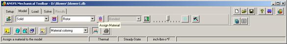
K. Next,
we will assign this material to the rotor geometry. In the MTB, pick the Assign Material
button.
4.1.K08D0C9EA79F9BACE118C8200AA004BA90B02000000080000000E0000005F005200650066003500300037003100350039003300380034000000
4.1.B08D0C9EA79F9BACE118C8200AA004BA90B02000000080000000E0000005F005200650066003400390039003500350032003700320030000000
4.1.K08D0C9EA79F9BACE118C8200AA004BA90B02000000080000000E0000005F005200650066003500300037003100350039003300380034000000
4.1.B08D0C9EA79F9BACE118C8200AA004BA90B02000000080000000E0000005F005200650066003400390039003500350032003700320030000000
|
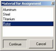
L. Highlight
Rotor in the material list.
M. Continue
4.1.B08D0C9EA79F9BACE118C8200AA004BA90B02000000080000000E0000005F005200650066003400390039003500350032003700320030000000
4.1.B08D0C9EA79F9BACE118C8200AA004BA90B02000000080000000E0000005F005200650066003400390039003500350032003700320030000000
|
4.1.M08D0C9EA79F9BACE118C8200AA004BA90B02000000080000000E0000005F005200650066003500300037003100350039003300390032000000
4.1.B08D0C9EA79F9BACE118C8200AA004BA90B02000000080000000E0000005F005200650066003400390039003500350032003700320030000000
4.1.M08D0C9EA79F9BACE118C8200AA004BA90B02000000080000000E0000005F005200650066003500300037003100350039003300390032000000
4.1.B08D0C9EA79F9BACE118C8200AA004BA90B02000000080000000E0000005F005200650066003400390039003500350032003700320030000000
|
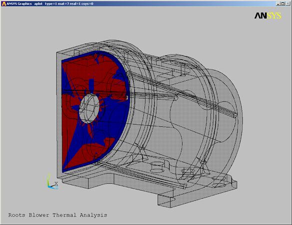
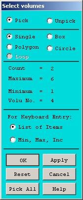
N.
 A dialog box will appear for you to select
the volumes for the rotor. In the
graphics window, click and hold the left mouse button over the rotor. If the wrong volume is highlighted, drag the
cursor around until the rotor highlights. The selection is not made until you release the mouse button.
A dialog box will appear for you to select
the volumes for the rotor. In the
graphics window, click and hold the left mouse button over the rotor. If the wrong volume is highlighted, drag the
cursor around until the rotor highlights. The selection is not made until you release the mouse button.
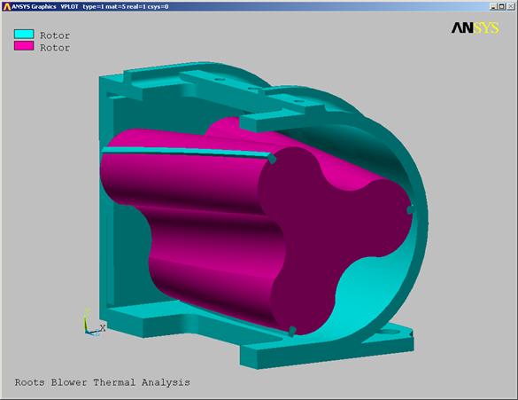
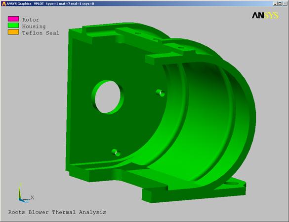
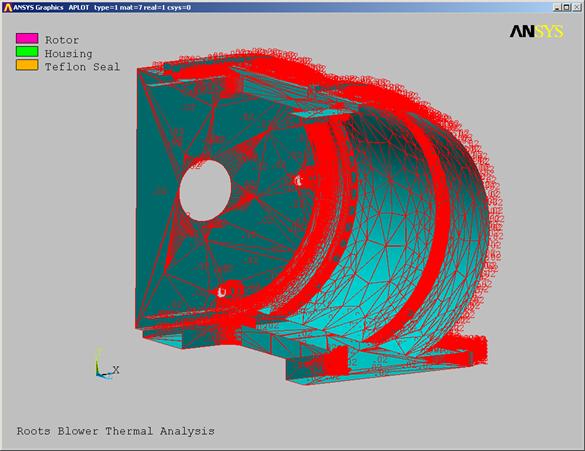
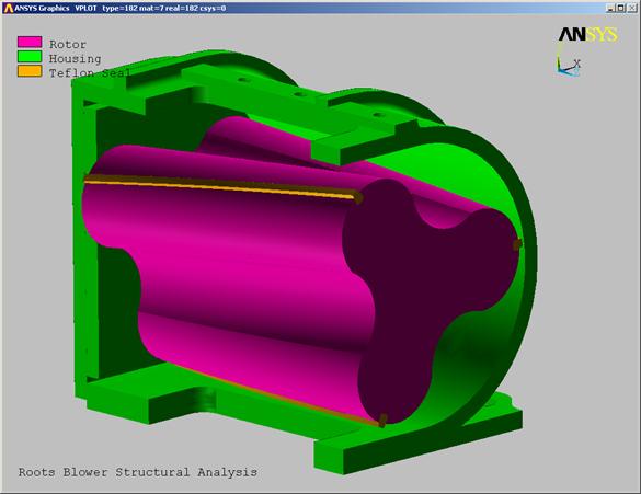
O. OK. The plot will change and color code the rotor
as shown below.
4.1.B08D0C9EA79F9BACE118C8200AA004BA90B02000000080000000E0000005F005200650066003400390039003500350032003700320030000000
4.1.B08D0C9EA79F9BACE118C8200AA004BA90B02000000080000000E0000005F005200650066003400390039003500350032003700320030000000
|
4.1.B08D0C9EA79F9BACE118C8200AA004BA90B02000000080000000E0000005F005200650066003400390039003500350032003700320030000000
4.1.B08D0C9EA79F9BACE118C8200AA004BA90B02000000080000000E0000005F005200650066003400390039003500350032003700320030000000
|
Housing
Material Properties:
A. In
the material list, pick New Material.
4.2.A08D0C9EA79F9BACE118C8200AA004BA90B02000000080000000E0000005F005200650066003500300037003100360032003200390033000000
008D0C9EA79F9BACE118C8200AA004BA90B02000000080000000E0000005F005200650066003400390039003500350032003300310034000000
4.2.A08D0C9EA79F9BACE118C8200AA004BA90B02000000080000000E0000005F005200650066003500300037003100360032003200390033000000
008D0C9EA79F9BACE118C8200AA004BA90B02000000080000000E0000005F005200650066003400390039003500350032003300310034000000
|


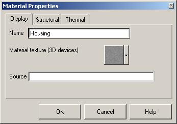
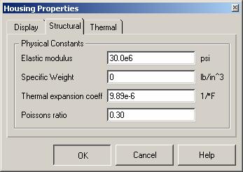
B. A
dialog box will appear for you to define this material. Enter a name of Housing.
C. Pick
the Structural Tab.
4.2.B08D0C9EA79F9BACE118C8200AA004BA90B02000000080000000E0000005F005200650066003500300037003100360032003300310034000000
4.1.B08D0C9EA79F9BACE118C8200AA004BA90B02000000080000000E0000005F005200650066003400390039003500350032003700320030000000
4.2.B08D0C9EA79F9BACE118C8200AA004BA90B02000000080000000E0000005F005200650066003500300037003100360032003300310034000000
4.1.B08D0C9EA79F9BACE118C8200AA004BA90B02000000080000000E0000005F005200650066003400390039003500350032003700320030000000
|
4.2.C08D0C9EA79F9BACE118C8200AA004BA90B02000000080000000E0000005F005200650066003500300037003100360032003300320037000000
4.1.B08D0C9EA79F9BACE118C8200AA004BA90B02000000080000000E0000005F005200650066003400390039003500350032003700320030000000
4.2.C08D0C9EA79F9BACE118C8200AA004BA90B02000000080000000E0000005F005200650066003500300037003100360032003300320037000000
4.1.B08D0C9EA79F9BACE118C8200AA004BA90B02000000080000000E0000005F005200650066003400390039003500350032003700320030000000
|
D. For
Elastic modulus, enter: 30.0e6
E. For
Specific Weight, enter: 0
F. For
Thermal expansion coeff, enter: 9.89e-6
G. For
Poissons ratio, enter: 0.30
H.
4.2.E08D0C9EA79F9BACE118C8200AA004BA90B02000000080000000E0000005F005200650066003500300037003100360032003300360037000000
4.2.E08D0C9EA79F9BACE118C8200AA004BA90B02000000080000000E0000005F005200650066003500300037003100360032003300360037000000
|
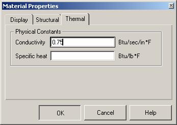
Pick
the Thermal tab to define the thermal properties.
I. For
4.2.H08D0C9EA79F9BACE118C8200AA004BA90B02000000080000000E0000005F005200650066003500300037003100360032003300390038000000
4.2.H08D0C9EA79F9BACE118C8200AA004BA90B02000000080000000E0000005F005200650066003500300037003100360032003300390038000000
|
4.2.D08D0C9EA79F9BACE118C8200AA004BA90B02000000080000000E0000005F005200650066003500300037003100360032003100330032000000
4.1.B08D0C9EA79F9BACE118C8200AA004BA90B02000000080000000E0000005F005200650066003400390039003500350032003700320030000000
4.2.D08D0C9EA79F9BACE118C8200AA004BA90B02000000080000000E0000005F005200650066003500300037003100360032003100330032000000
4.1.B08D0C9EA79F9BACE118C8200AA004BA90B02000000080000000E0000005F005200650066003400390039003500350032003700320030000000
|
4.2.G08D0C9EA79F9BACE118C8200AA004BA90B02000000080000000E0000005F005200650066003500310036003200310038003100360036000000
4.1.B08D0C9EA79F9BACE118C8200AA004BA90B02000000080000000E0000005F005200650066003400390039003500350032003700320030000000
4.2.F08D0C9EA79F9BACE118C8200AA004BA90B02000000080000000E0000005F005200650066003500300037003100360032003300370038000000
4.1.B08D0C9EA79F9BACE118C8200AA004BA90B02000000080000000E0000005F005200650066003400390039003500350032003700320030000000
|
4.2.F08D0C9EA79F9BACE118C8200AA004BA90B02000000080000000E0000005F005200650066003500300037003100360032003300370038000000
4.1.B08D0C9EA79F9BACE118C8200AA004BA90B02000000080000000E0000005F005200650066003400390039003500350032003700320030000000
4.2.F08D0C9EA79F9BACE118C8200AA004BA90B02000000080000000E0000005F005200650066003500300037003100360032003300370038000000
4.1.B08D0C9EA79F9BACE118C8200AA004BA90B02000000080000000E0000005F005200650066003400390039003500350032003700320030000000
|
J. Specific
heat is not needed in a steady state analysis, so we will leave that field
blank. Pick OK.
4.2.I08D0C9EA79F9BACE118C8200AA004BA90B02000000080000000E0000005F005200650066003500300037003100360032003400310031000000 23323j921x
4.1.B08D0C9EA79F9BACE118C8200AA004BA90B02000000080000000E0000005F005200650066003400390039003500350032003700320030000000
4.2.I08D0C9EA79F9BACE118C8200AA004BA90B02000000080000000E0000005F005200650066003500300037003100360032003400310031000000 23323j921x
4.1.B08D0C9EA79F9BACE118C8200AA004BA90B02000000080000000E0000005F005200650066003400390039003500350032003700320030000000
|
4.2.J08D0C9EA79F9BACE118C8200AA004BA90B02000000080000000E0000005F005200650066003500300037003100360032003400320031000000 23323j921x
4.1.B08D0C9EA79F9BACE118C8200AA004BA90B02000000080000000E0000005F005200650066003400390039003500350032003700320030000000
4.2.J08D0C9EA79F9BACE118C8200AA004BA90B02000000080000000E0000005F005200650066003500300037003100360032003400320031000000 23323j921x
4.1.B08D0C9EA79F9BACE118C8200AA004BA90B02000000080000000E0000005F005200650066003400390039003500350032003700320030000000
|
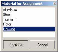
K. Next,
we will assign this material to the rotor geometry. In the MTB, pick the Assign Material
button.
4.2.K08D0C9EA79F9BACE118C8200AA004BA90B02000000080000000E0000005F005200650066003500300037003100360032003400340039000000
4.1.B08D0C9EA79F9BACE118C8200AA004BA90B02000000080000000E0000005F005200650066003400390039003500350032003700320030000000
4.2.K08D0C9EA79F9BACE118C8200AA004BA90B02000000080000000E0000005F005200650066003500300037003100360032003400340039000000
4.1.B08D0C9EA79F9BACE118C8200AA004BA90B02000000080000000E0000005F005200650066003400390039003500350032003700320030000000
|
L. Highlight
Housing in the material list.
M. Continue.
4.2.L08D0C9EA79F9BACE118C8200AA004BA90B02000000080000000E0000005F005200650066003500300037003100360032003400360034000000
4.1.B08D0C9EA79F9BACE118C8200AA004BA90B02000000080000000E0000005F005200650066003400390039003500350032003700320030000000
4.2.L08D0C9EA79F9BACE118C8200AA004BA90B02000000080000000E0000005F005200650066003500300037003100360032003400360034000000
4.1.B08D0C9EA79F9BACE118C8200AA004BA90B02000000080000000E0000005F005200650066003400390039003500350032003700320030000000
|
4.2.M08D0C9EA79F9BACE118C8200AA004BA90B02000000080000000E0000005F005200650066003500300037003100360032003400370032000000
4.1.B08D0C9EA79F9BACE118C8200AA004BA90B02000000080000000E0000005F005200650066003400390039003500350032003700320030000000
4.2.M08D0C9EA79F9BACE118C8200AA004BA90B02000000080000000E0000005F005200650066003500300037003100360032003400370032000000
4.1.B08D0C9EA79F9BACE118C8200AA004BA90B02000000080000000E0000005F005200650066003400390039003500350032003700320030000000
|
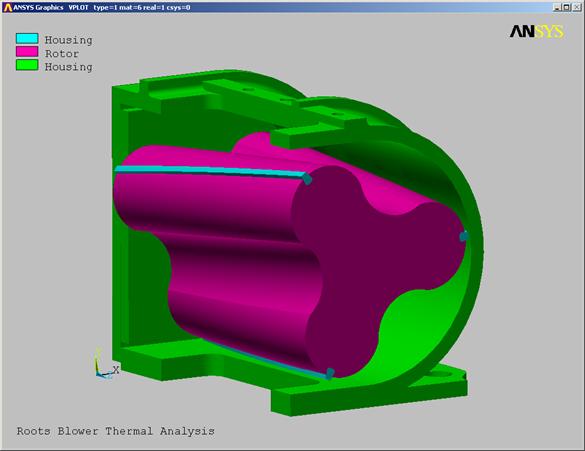
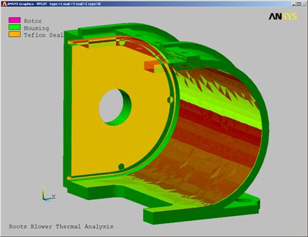
N.
 A dialog box will appear for you to select
the volumes for the case material. Pick
the case and the bearing plate at the back of the rotor.
A dialog box will appear for you to select
the volumes for the case material. Pick
the case and the bearing plate at the back of the rotor.
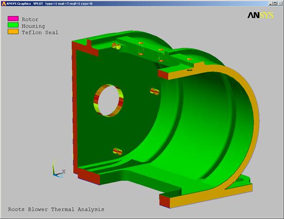
O. OK. The plot will change and color code the rotor
as shown below.
4.1.B08D0C9EA79F9BACE118C8200AA004BA90B02000000080000000E0000005F005200650066003400390039003500350032003700320030000000
4.1.B08D0C9EA79F9BACE118C8200AA004BA90B02000000080000000E0000005F005200650066003400390039003500350032003700320030000000
|
4.1.B08D0C9EA79F9BACE118C8200AA004BA90B02000000080000000E0000005F005200650066003400390039003500350032003700320030000000
4.1.B08D0C9EA79F9BACE118C8200AA004BA90B02000000080000000E0000005F005200650066003400390039003500350032003700320030000000
|
Seal
Material Properties:
A. In
the material list, pick New Material.
4.3.A08D0C9EA79F9BACE118C8200AA004BA90B02000000080000000E0000005F005200650066003500300037003100360032003200300033000000
008D0C9EA79F9BACE118C8200AA004BA90B02000000080000000E0000005F005200650066003400390039003500350032003300310034000000
4.3.A08D0C9EA79F9BACE118C8200AA004BA90B02000000080000000E0000005F005200650066003500300037003100360032003200300033000000
008D0C9EA79F9BACE118C8200AA004BA90B02000000080000000E0000005F005200650066003400390039003500350032003300310034000000
|
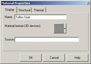
B. A
dialog box will appear for you to define this material. Enter a name of Teflon Seal.
C. Pick
the Structural Tab.
4.3.B08D0C9EA79F9BACE118C8200AA004BA90B02000000080000000E0000005F005200650066003500300037003100360032003200310034000000
4.1.B08D0C9EA79F9BACE118C8200AA004BA90B02000000080000000E0000005F005200650066003400390039003500350032003700320030000000
4.3.B08D0C9EA79F9BACE118C8200AA004BA90B02000000080000000E0000005F005200650066003500300037003100360032003200310034000000
4.1.B08D0C9EA79F9BACE118C8200AA004BA90B02000000080000000E0000005F005200650066003400390039003500350032003700320030000000
|
4.3.C08D0C9EA79F9BACE118C8200AA004BA90B02000000080000000E0000005F005200650066003500300037003100360032003200320032000000
4.1.B08D0C9EA79F9BACE118C8200AA004BA90B02000000080000000E0000005F005200650066003400390039003500350032003700320030000000
4.3.C08D0C9EA79F9BACE118C8200AA004BA90B02000000080000000E0000005F005200650066003500300037003100360032003200320032000000
4.1.B08D0C9EA79F9BACE118C8200AA004BA90B02000000080000000E0000005F005200650066003400390039003500350032003700320030000000
|
D. For
Elastic modulus, enter: 67000
E. For
Specific Weight, enter: 0.078
F. For
Thermal expansion coeff, enter: 48.0e-6
G. For
Poissons ratio, enter: 0.46
H.
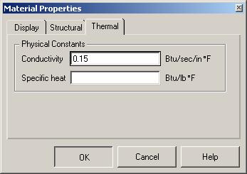
Pick
the Thermal tab to define the thermal properties.
I. For
4.3.H08D0C9EA79F9BACE118C8200AA004BA90B02000000080000000E0000005F005200650066003500300037003700350037003800380032000000
4.1.B08D0C9EA79F9BACE118C8200AA004BA90B02000000080000000E0000005F005200650066003400390039003500350032003700320030000000
4.1.B08D0C9EA79F9BACE118C8200AA004BA90B02000000080000000E0000005F005200650066003400390039003500350032003700320030000000
|
4.3.E08D0C9EA79F9BACE118C8200AA004BA90B02000000080000000E0000005F005200650066003500300037003100360032003100380031000000 23323j921x
4.1.B08D0C9EA79F9BACE118C8200AA004BA90B02000000080000000E0000005F005200650066003400390039003500350032003700320030000000
4.3.E08D0C9EA79F9BACE118C8200AA004BA90B02000000080000000E0000005F005200650066003500300037003100360032003100380031000000 23323j921x
4.1.B08D0C9EA79F9BACE118C8200AA004BA90B02000000080000000E0000005F005200650066003400390039003500350032003700320030000000
|
4.3.D08D0C9EA79F9BACE118C8200AA004BA90B02000000080000000E0000005F005200650066003500300037003100360032003600380037000000
4.1.B08D0C9EA79F9BACE118C8200AA004BA90B02000000080000000E0000005F005200650066003400390039003500350032003700320030000000
4.3.D08D0C9EA79F9BACE118C8200AA004BA90B02000000080000000E0000005F005200650066003500300037003100360032003600380037000000
4.1.B08D0C9EA79F9BACE118C8200AA004BA90B02000000080000000E0000005F005200650066003400390039003500350032003700320030000000
|
4.3.G08D0C9EA79F9BACE118C8200AA004BA90B02000000080000000E0000005F005200650066003500300037003100360032003700320037000000
4.1.B08D0C9EA79F9BACE118C8200AA004BA90B02000000080000000E0000005F005200650066003400390039003500350032003700320030000000
4.3.G08D0C9EA79F9BACE118C8200AA004BA90B02000000080000000E0000005F005200650066003500300037003100360032003700320037000000
4.1.B08D0C9EA79F9BACE118C8200AA004BA90B02000000080000000E0000005F005200650066003400390039003500350032003700320030000000
|
4.3.F08D0C9EA79F9BACE118C8200AA004BA90B02000000080000000E0000005F005200650066003500300037003100360032003700310035000000
4.1.B08D0C9EA79F9BACE118C8200AA004BA90B02000000080000000E0000005F005200650066003400390039003500350032003700320030000000
4.3.F08D0C9EA79F9BACE118C8200AA004BA90B02000000080000000E0000005F005200650066003500300037003100360032003700310035000000
4.1.B08D0C9EA79F9BACE118C8200AA004BA90B02000000080000000E0000005F005200650066003400390039003500350032003700320030000000
|
J. Specific
heat is not needed in a steady state analysis, so we will leave that field
blank. Pick OK
4.3.I08D0C9EA79F9BACE118C8200AA004BA90B02000000080000000E0000005F005200650066003500300037003100360032003700340032000000
4.1.B08D0C9EA79F9BACE118C8200AA004BA90B02000000080000000E0000005F005200650066003400390039003500350032003700320030000000
4.3.I08D0C9EA79F9BACE118C8200AA004BA90B02000000080000000E0000005F005200650066003500300037003100360032003700340032000000
4.1.B08D0C9EA79F9BACE118C8200AA004BA90B02000000080000000E0000005F005200650066003400390039003500350032003700320030000000
|
4.3.J08D0C9EA79F9BACE118C8200AA004BA90B02000000080000000E0000005F005200650066003500300037003100360032003700360031000000 23323j921x
4.1.B08D0C9EA79F9BACE118C8200AA004BA90B02000000080000000E0000005F005200650066003400390039003500350032003700320030000000
4.3.J08D0C9EA79F9BACE118C8200AA004BA90B02000000080000000E0000005F005200650066003500300037003100360032003700360031000000 23323j921x
4.1.B08D0C9EA79F9BACE118C8200AA004BA90B02000000080000000E0000005F005200650066003400390039003500350032003700320030000000
|
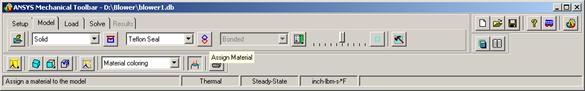
K. Next,
we will assign this material to the rotor geometry. In the MTB, pick the Assign Material
button.
4.3.K08D0C9EA79F9BACE118C8200AA004BA90B02000000080000000E0000005F005200650066003500300037003100360033003000310032000000
4.1.B08D0C9EA79F9BACE118C8200AA004BA90B02000000080000000E0000005F005200650066003400390039003500350032003700320030000000
4.3.K08D0C9EA79F9BACE118C8200AA004BA90B02000000080000000E0000005F005200650066003500300037003100360033003000310032000000
4.1.B08D0C9EA79F9BACE118C8200AA004BA90B02000000080000000E0000005F005200650066003400390039003500350032003700320030000000
|
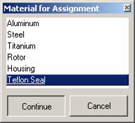
L. Highlight
Teflon Seal in the material list.
M. Continue
4.3.L08D0C9EA79F9BACE118C8200AA004BA90B02000000080000000E0000005F005200650066003500300037003100360033003000320036000000
4.1.B08D0C9EA79F9BACE118C8200AA004BA90B02000000080000000E0000005F005200650066003400390039003500350032003700320030000000
4.3.L08D0C9EA79F9BACE118C8200AA004BA90B02000000080000000E0000005F005200650066003500300037003100360033003000320036000000
4.1.B08D0C9EA79F9BACE118C8200AA004BA90B02000000080000000E0000005F005200650066003400390039003500350032003700320030000000
|
4.3.M08D0C9EA79F9BACE118C8200AA004BA90B02000000080000000E0000005F005200650066003500300037003100360033003000330036000000
4.1.B08D0C9EA79F9BACE118C8200AA004BA90B02000000080000000E0000005F005200650066003400390039003500350032003700320030000000
4.3.M08D0C9EA79F9BACE118C8200AA004BA90B02000000080000000E0000005F005200650066003500300037003100360033003000330036000000
4.1.B08D0C9EA79F9BACE118C8200AA004BA90B02000000080000000E0000005F005200650066003400390039003500350032003700320030000000
|
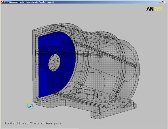
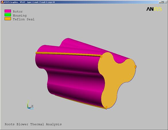
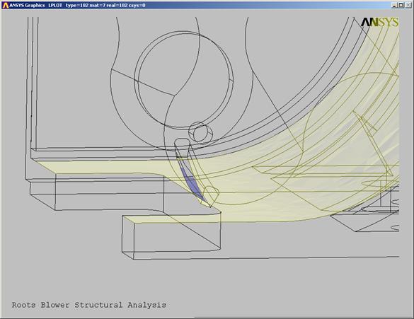
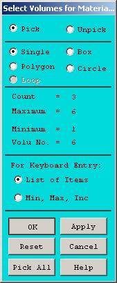
N. A
dialog box will appear for you to select the volumes for the seals. Pick the three seals on the OD of the
rotor. The hot spot for each volume as
at it's geometric center. Even though
some of them may be hidden from view, you can still select them by picking at
their center location.
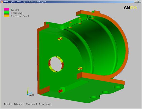
O. OK. The plot will change and color code the rotor
as shown below.
4.1.B08D0C9EA79F9BACE118C8200AA004BA90B02000000080000000E0000005F005200650066003400390039003500350032003700320030000000
4.1.B08D0C9EA79F9BACE118C8200AA004BA90B02000000080000000E0000005F005200650066003400390039003500350032003700320030000000
|
4.1.B08D0C9EA79F9BACE118C8200AA004BA90B02000000080000000E0000005F005200650066003400390039003500350032003700320030000000
4.1.B08D0C9EA79F9BACE118C8200AA004BA90B02000000080000000E0000005F005200650066003400390039003500350032003700320030000000
|
Contact
Definition:
We are ready to
define the contact surfaces. ANSYS can
automatically detect areas that are in or near contact and define contact
pairs.
Define
Contact Pairs:
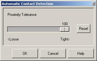
A. Click
and hold the View/Modify Contact button until the fly-out appears. Pick the Auto Create Contact button.
5.1.A08D0C9EA79F9BACE118C8200AA004BA90B02000000080000000E0000005F005200650066003500300037003700350031003000390035000000
Error!
Reference source not found.
5.1.A08D0C9EA79F9BACE118C8200AA004BA90B02000000080000000E0000005F005200650066003500300037003700350031003000390035000000
Error!
Reference source not found.
|


B. ANSYS
will search for surfaces that are within a certain proximity to each other when
defining contact pairs. A proximity
tolerance of 100 (Tight) means that surfaces must be exactly touching in order
for contact to be defined. For our
model, set the tolerance to 100.
C. Pick OK. ANSYS will create the contact pairs. This may take a few minutes.
5.1.B08D0C9EA79F9BACE118C8200AA004BA90B02000000080000000E0000005F005200650066003500300037003700350031003100300037000000
Error!
Reference source not found.
5.1.B08D0C9EA79F9BACE118C8200AA004BA90B02000000080000000E0000005F005200650066003500300037003700350031003100300037000000
Error!
Reference source not found.
|
5.1.C08D0C9EA79F9BACE118C8200AA004BA90B02000000080000000E0000005F005200650066003500300037003700350031003300350031000000 23323j921x
5.1.C08D0C9EA79F9BACE118C8200AA004BA90B02000000080000000E0000005F005200650066003500300037003700350031003300350031000000 23323j921x
|
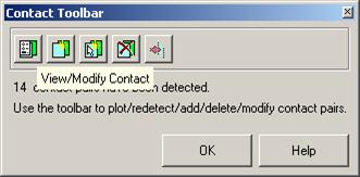
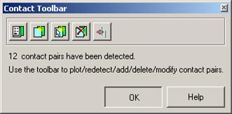
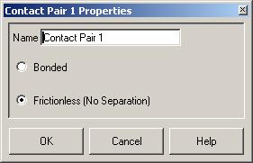
D. When ANSYS finishes, a
dialog will appear indicating that 14 contact pairs have been created. This dialog contains several options as shown
below.
View/Modify Contact: View existing contact pairs and modify
their properties.
View/Modify Contact: View existing contact pairs and modify their properties.
View/Modify Contact: View existing contact pairs and modify
their properties.
View/Modify Contact: View existing contact pairs and modify their properties.
|
Auto Create
Contact: Automatically detect
and create contact pairs.
Auto Create Contact: Automatically detect and create contact pairs.
Auto Create Contact: Automatically detect and create contact
pairs.
Auto Create Contact: Automatically detect and create contact pairs.
|
Manually Create
Contact: Define contact pairs
by picking.
Manually Create Contact: Define contact pairs by picking.
Manually Create Contact: Define contact pairs by picking.
Manually Create Contact: Define contact pairs by picking.
|
Delete Contact: Delete Contact Pairs
Delete Contact: Delete Contact Pairs
Delete Contact: Delete Contact Pairs
Delete Contact: Delete Contact Pairs
|
Modify Contact Pair Normals: I.e. the normal directions of each
contact pair must point towards each other to be correct.
Modify Contact Pair Normals: I.e. the normal directions of each contact
pair must point towards each other to be correct.
Modify Contact Pair Normals: I.e. the normal directions of each
contact pair must point towards each other to be correct.
Modify Contact Pair Normals: I.e. the normal directions of each
contact pair must point towards each other to be correct.
|
E.
5.1.E08D0C9EA79F9BACE118C8200AA004BA90B02000000080000000E0000005F005200650066003500300037003700350031003700370031000000 23323j921x
5.1.E08D0C9EA79F9BACE118C8200AA004BA90B02000000080000000E0000005F005200650066003500300037003700350031003700370031000000 23323j921x
|

In
the Contact Toolbar, pick the View/Modify Contact button.
F.
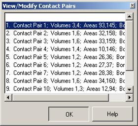
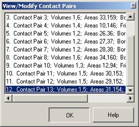
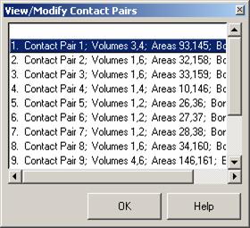 A dialog will appear showing a list of the
contact pairs.
A dialog will appear showing a list of the
contact pairs.
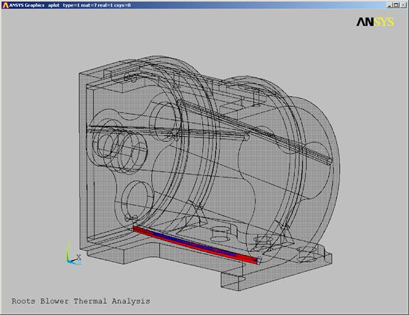
G. The
first contact pair will be highlighted in the graphics window.
5.1.F08D0C9EA79F9BACE118C8200AA004BA90B02000000080000000E0000005F005200650066003500300037003700350032003500330030000000
5.1.F08D0C9EA79F9BACE118C8200AA004BA90B02000000080000000E0000005F005200650066003500300037003700350032003500330030000000
|
5.1.G08D0C9EA79F9BACE118C8200AA004BA90B02000000080000000E0000005F005200650066003500300037003700350032003500340032000000
5.1.G08D0C9EA79F9BACE118C8200AA004BA90B02000000080000000E0000005F005200650066003500300037003700350032003500340032000000
|
H.
5.1.H08D0C9EA79F9BACE118C8200AA004BA90B02000000080000000E0000005F005200650066003500300037003700350033003000300034000000
5.1.H08D0C9EA79F9BACE118C8200AA004BA90B02000000080000000E0000005F005200650066003500300037003700350033003000300034000000
|

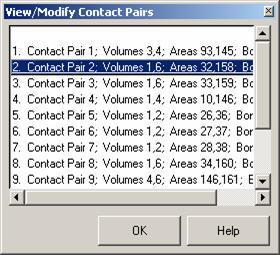 In the View/Modify Contact Pairs dialog,
pick: Contact Pair 2: to view the next pair.
In the View/Modify Contact Pairs dialog,
pick: Contact Pair 2: to view the next pair.
I. The
next pair will be highlighted in the graphics window.
5.1.I08D0C9EA79F9BACE118C8200AA004BA90B02000000080000000E0000005F005200650066003500300037003700350033003100350032000000
5.1.I08D0C9EA79F9BACE118C8200AA004BA90B02000000080000000E0000005F005200650066003500300037003700350033003100350032000000
|
J.

5.1.K08D0C9EA79F9BACE118C8200AA004BA90B02000000080000000E0000005F005200650066003500300037003700350033003700330032000000
5.1.K08D0C9EA79F9BACE118C8200AA004BA90B02000000080000000E0000005F005200650066003500300037003700350033003700330032000000
|

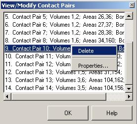
 Repeat
this process and view all the contact pairs that were defined for you. In our model, the auto-contact feature
created two extra pairs that aren't necessary. When you get to pair 9, we will delete this one. (We could have retained this pair, but it is
a small feature and we want to demonstrate the delete capability).
Repeat
this process and view all the contact pairs that were defined for you. In our model, the auto-contact feature
created two extra pairs that aren't necessary. When you get to pair 9, we will delete this one. (We could have retained this pair, but it is
a small feature and we want to demonstrate the delete capability).
K. With Contact Pair 9
highlighted, click the right mouse button until the delete option appears. Then pick the Delete button.
5.1.J08D0C9EA79F9BACE118C8200AA004BA90B02000000080000000E0000005F005200650066003500300037003700350033003500330035000000
5.1.J08D0C9EA79F9BACE118C8200AA004BA90B02000000080000000E0000005F005200650066003500300037003700350033003500330035000000
|
L.
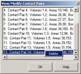 Continue cycling through the contact pairs
until you reach Contact Pair 14: Like the previous pair, we could retain this one, but we will delete it
for demonstration purposes.
Continue cycling through the contact pairs
until you reach Contact Pair 14: Like the previous pair, we could retain this one, but we will delete it
for demonstration purposes.
5.1.L08D0C9EA79F9BACE118C8200AA004BA90B02000000080000000E0000005F005200650066003500300037003700350034003300360030000000
5.1.L08D0C9EA79F9BACE118C8200AA004BA90B02000000080000000E0000005F005200650066003500300037003700350034003300360030000000
|
M. Delete
this one also. With Contact Pair 14: highlighted, pick the right mouse button until
the delete button appears. Then pick the
delete button.
5.1.M08D0C9EA79F9BACE118C8200AA004BA90B02000000080000000E0000005F005200650066003500300037003700350034003300370031000000 23323j921x
5.1.M08D0C9EA79F9BACE118C8200AA004BA90B02000000080000000E0000005F005200650066003500300037003700350034003300370031000000 23323j921x
|
N. We
have completed the thermal contact element definition. Pick OK in the View/Modify Contact
Pair dialog.
5.1.N08D0C9EA79F9BACE118C8200AA004BA90B02000000080000000E0000005F005200650066003500300037003700350034003600340037000000
5.1.N08D0C9EA79F9BACE118C8200AA004BA90B02000000080000000E0000005F005200650066003500300037003700350034003600340037000000
|
O. Pick
OK in the Contact Toolbar.
5.1.O08D0C9EA79F9BACE118C8200AA004BA90B02000000080000000E0000005F005200650066003500300037003700350034003600350037000000
5.1.O08D0C9EA79F9BACE118C8200AA004BA90B02000000080000000E0000005F005200650066003500300037003700350034003600350037000000
|
Meshing:
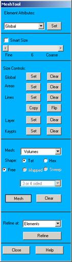
Mesh
Model:
A. In
the MTB, pick the Meshtool button.
4.1.B08D0C9EA79F9BACE118C8200AA004BA90B02000000080000000E0000005F005200650066003400390039003500350032003700320030000000
4.1.B08D0C9EA79F9BACE118C8200AA004BA90B02000000080000000E0000005F005200650066003400390039003500350032003700320030000000
|
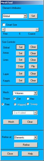
B. We
mesh this model with a default element size instead of the smartsize
option. Make sure the Smart size
button is not checked.
C.
4.1.B08D0C9EA79F9BACE118C8200AA004BA90B02000000080000000E0000005F005200650066003400390039003500350032003700320030000000
4.1.B08D0C9EA79F9BACE118C8200AA004BA90B02000000080000000E0000005F005200650066003400390039003500350032003700320030000000
|
6.1.C08D0C9EA79F9BACE118C8200AA004BA90B02000000080000000E0000005F005200650066003500300037003200330039003800370034000000
4.1.B08D0C9EA79F9BACE118C8200AA004BA90B02000000080000000E0000005F005200650066003400390039003500350032003700320030000000
6.1.C08D0C9EA79F9BACE118C8200AA004BA90B02000000080000000E0000005F005200650066003500300037003200330039003800370034000000
4.1.B08D0C9EA79F9BACE118C8200AA004BA90B02000000080000000E0000005F005200650066003400390039003500350032003700320030000000
|
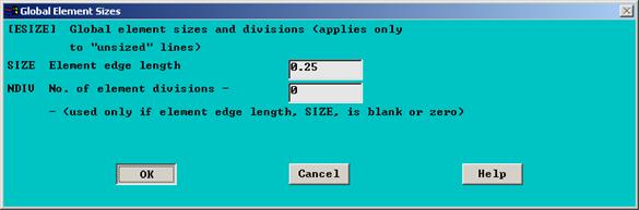
D. For
Element edge length, enter: 0.25
E.
4.1.B08D0C9EA79F9BACE118C8200AA004BA90B02000000080000000E0000005F005200650066003400390039003500350032003700320030000000
4.1.B08D0C9EA79F9BACE118C8200AA004BA90B02000000080000000E0000005F005200650066003400390039003500350032003700320030000000
|
6.1.E08D0C9EA79F9BACE118C8200AA004BA90B02000000080000000E0000005F005200650066003500300037003200340030003000360031000000 23323j921x
4.1.B08D0C9EA79F9BACE118C8200AA004BA90B02000000080000000E0000005F005200650066003400390039003500350032003700320030000000
6.1.E08D0C9EA79F9BACE118C8200AA004BA90B02000000080000000E0000005F005200650066003500300037003200340030003000360031000000 23323j921x
4.1.B08D0C9EA79F9BACE118C8200AA004BA90B02000000080000000E0000005F005200650066003400390039003500350032003700320030000000
|
OK.
F. In
the Meshtool, pick the Mesh button.
G.
6.1.G08D0C9EA79F9BACE118C8200AA004BA90B02000000080000000E0000005F005200650066003500300037003200340030003400340038000000
4.1.B08D0C9EA79F9BACE118C8200AA004BA90B02000000080000000E0000005F005200650066003400390039003500350032003700320030000000
6.1.G08D0C9EA79F9BACE118C8200AA004BA90B02000000080000000E0000005F005200650066003500300037003200340030003400340038000000
4.1.B08D0C9EA79F9BACE118C8200AA004BA90B02000000080000000E0000005F005200650066003400390039003500350032003700320030000000
|

6.1.F08D0C9EA79F9BACE118C8200AA004BA90B02000000080000000E0000005F005200650066003500300037003200340030003400320030000000
4.1.B08D0C9EA79F9BACE118C8200AA004BA90B02000000080000000E0000005F005200650066003400390039003500350032003700320030000000
6.1.F08D0C9EA79F9BACE118C8200AA004BA90B02000000080000000E0000005F005200650066003500300037003200340030003400320030000000
4.1.B08D0C9EA79F9BACE118C8200AA004BA90B02000000080000000E0000005F005200650066003400390039003500350032003700320030000000
|

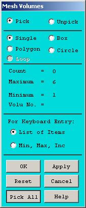
A
dialog will appear for you to select volumes for meshing. Pick the Pick All button.
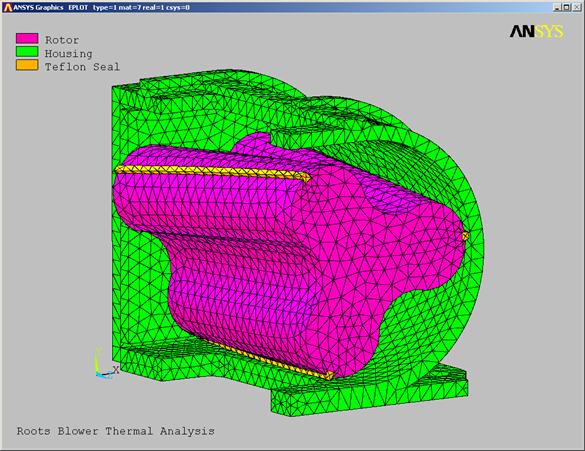
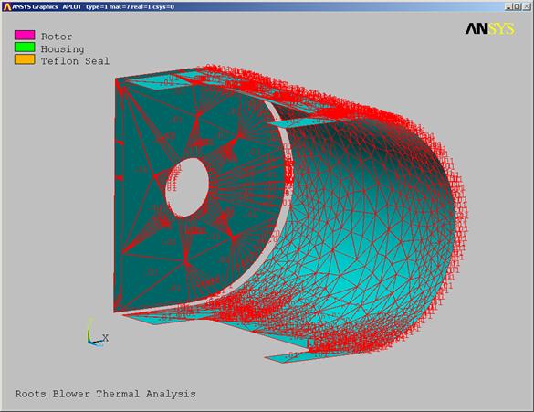
H. It
may take a few minutes to mesh your model. When complete, pick the Element Plot fly-out button in the MTB.
6.1.H08D0C9EA79F9BACE118C8200AA004BA90B02000000080000000E0000005F005200650066003500300037003200340030003700360031000000 23323j921x
4.1.B08D0C9EA79F9BACE118C8200AA004BA90B02000000080000000E0000005F005200650066003400390039003500350032003700320030000000
6.1.H08D0C9EA79F9BACE118C8200AA004BA90B02000000080000000E0000005F005200650066003500300037003200340030003700360031000000 23323j921x
4.1.B08D0C9EA79F9BACE118C8200AA004BA90B02000000080000000E0000005F005200650066003400390039003500350032003700320030000000
|
I. The
mesh should look like the one below:
4.1.B08D0C9EA79F9BACE118C8200AA004BA90B02000000080000000E0000005F005200650066003400390039003500350032003700320030000000
4.1.B08D0C9EA79F9BACE118C8200AA004BA90B02000000080000000E0000005F005200650066003400390039003500350032003700320030000000
|
Thermal
Loads Application:
We will apply
two convection loads to our model. The
exterior surfaces of the housing will have an ambient condition of h=10,
T=70. The internal surfaces of the
housing and rotor will have h=100, T=200. Since this is a complex model, it will be difficult select surfaces for
the load application. We will utilize
the powerful select logic in ANSYS to help us.
The procedure
will be to select groups of surfaces for load application and store these as
components prior to applying loads. This
will save us from having to select surface groups again when we apply pressure
loads during the structural analysis.
Rotor
Convection Surface Selection.
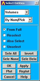
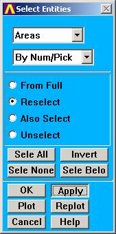
A. In
the Utilities menu, pick the Select button.
B. Entities.
C. Volumes.
D.
4.1.B08D0C9EA79F9BACE118C8200AA004BA90B02000000080000000E0000005F005200650066003400390039003500350032003700320030000000
4.1.B08D0C9EA79F9BACE118C8200AA004BA90B02000000080000000E0000005F005200650066003400390039003500350032003700320030000000
|
 Apply.
4.1.B08D0C9EA79F9BACE118C8200AA004BA90B02000000080000000E0000005F005200650066003400390039003500350032003700320030000000
4.1.B08D0C9EA79F9BACE118C8200AA004BA90B02000000080000000E0000005F005200650066003400390039003500350032003700320030000000
|
7.1.C08D0C9EA79F9BACE118C8200AA004BA90B02000000080000000E0000005F005200650066003500300037003200350030003900350034000000
4.1.B08D0C9EA79F9BACE118C8200AA004BA90B02000000080000000E0000005F005200650066003400390039003500350032003700320030000000
7.1.C08D0C9EA79F9BACE118C8200AA004BA90B02000000080000000E0000005F005200650066003500300037003200350030003900350034000000
4.1.B08D0C9EA79F9BACE118C8200AA004BA90B02000000080000000E0000005F005200650066003400390039003500350032003700320030000000
|
7.1.B08D0C9EA79F9BACE118C8200AA004BA90B02000000080000000E0000005F005200650066003500300037003200350030003900340032000000
4.1.B08D0C9EA79F9BACE118C8200AA004BA90B02000000080000000E0000005F005200650066003400390039003500350032003700320030000000
7.1.B08D0C9EA79F9BACE118C8200AA004BA90B02000000080000000E0000005F005200650066003500300037003200350030003900340032000000
4.1.B08D0C9EA79F9BACE118C8200AA004BA90B02000000080000000E0000005F005200650066003400390039003500350032003700320030000000
|
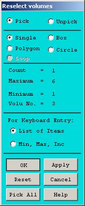
E. A dialog box will appear for
you to select volumes. Click and hold
the left button over the rotor. Release
the button when the rotor volume is highlighted. Pick the three Teflon strips as well. Even though one or more of them may be hidden
from view, you can still select them by picking near each of their center
locations.
Pick near each
Teflon seal center. Pick the rotor
also.
Pick near each Teflon seal center. Pick the rotor also.
|
F. OK
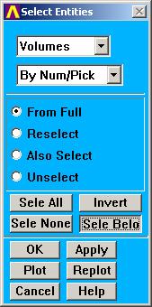
G. In
the Select Entities dialog, pick Sele Belo. This will select all the lower order entities
associated with the volume including the areas, lines, keypoints, nodes, and
elements.
H. Pick
the Replot button in the Select Entities dialog.
7.1.F08D0C9EA79F9BACE118C8200AA004BA90B02000000080000000E0000005F005200650066003500300037003200350031003400370031000000 23323j921x
4.1.B08D0C9EA79F9BACE118C8200AA004BA90B02000000080000000E0000005F005200650066003400390039003500350032003700320030000000
7.1.F08D0C9EA79F9BACE118C8200AA004BA90B02000000080000000E0000005F005200650066003500300037003200350031003400370031000000 23323j921x
4.1.B08D0C9EA79F9BACE118C8200AA004BA90B02000000080000000E0000005F005200650066003400390039003500350032003700320030000000
|
7.1.H08D0C9EA79F9BACE118C8200AA004BA90B02000000080000000E0000005F005200650066003500300037003700350038003100310033000000
|
7.1.G08D0C9EA79F9BACE118C8200AA004BA90B02000000080000000E0000005F005200650066003500300037003200350031003400380034000000
4.1.B08D0C9EA79F9BACE118C8200AA004BA90B02000000080000000E0000005F005200650066003400390039003500350032003700320030000000
7.1.G08D0C9EA79F9BACE118C8200AA004BA90B02000000080000000E0000005F005200650066003500300037003200350031003400380034000000
4.1.B08D0C9EA79F9BACE118C8200AA004BA90B02000000080000000E0000005F005200650066003400390039003500350032003700320030000000
|
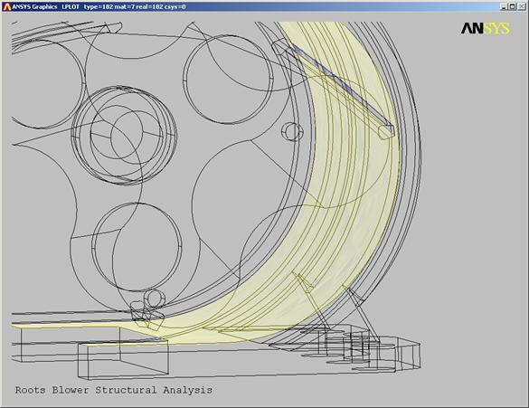
I. You
should see only the rotor areas as shown in the plot below:
7.1.I08D0C9EA79F9BACE118C8200AA004BA90B02000000080000000E0000005F005200650066003500300037003200350031003800390033000000
4.1.B08D0C9EA79F9BACE118C8200AA004BA90B02000000080000000E0000005F005200650066003400390039003500350032003700320030000000
7.1.I08D0C9EA79F9BACE118C8200AA004BA90B02000000080000000E0000005F005200650066003500300037003200350031003800390033000000
4.1.B08D0C9EA79F9BACE118C8200AA004BA90B02000000080000000E0000005F005200650066003400390039003500350032003700320030000000
|
J.
7.1.J08D0C9EA79F9BACE118C8200AA004BA90B02000000080000000E0000005F005200650066003500300037003200350032003600300036000000
4.1.B08D0C9EA79F9BACE118C8200AA004BA90B02000000080000000E0000005F005200650066003400390039003500350032003700320030000000
7.1.J08D0C9EA79F9BACE118C8200AA004BA90B02000000080000000E0000005F005200650066003500300037003200350032003600300036000000
4.1.B08D0C9EA79F9BACE118C8200AA004BA90B02000000080000000E0000005F005200650066003400390039003500350032003700320030000000
|
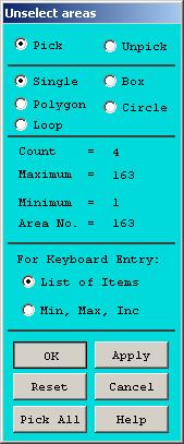
K. Unselect.
L. Apply.
M. Pick
the areas defining the symmetry cut planes of the rotor and the three Teflon
seals.
7.1.L08D0C9EA79F9BACE118C8200AA004BA90B02000000080000000E0000005F005200650066003500300037003200350032003600320038000000
7.1.L08D0C9EA79F9BACE118C8200AA004BA90B02000000080000000E0000005F005200650066003500300037003200350032003600320038000000
|
7.1.M08D0C9EA79F9BACE118C8200AA004BA90B02000000080000000E0000005F005200650066003500300037003200350032003700330034000000
7.1.M08D0C9EA79F9BACE118C8200AA004BA90B02000000080000000E0000005F005200650066003500300037003200350032003700330034000000
|

7.1.K08D0C9EA79F9BACE118C8200AA004BA90B02000000080000000E0000005F005200650066003500300037003200350032003600310038000000
7.1.K08D0C9EA79F9BACE118C8200AA004BA90B02000000080000000E0000005F005200650066003500300037003200350032003600310038000000
|
N.
You should have four
areas selected.
|
|


7.1.N08D0C9EA79F9BACE118C8200AA004BA90B02000000080000000E0000005F005200650066003500300037003200350033003000340035000000
7.1.N08D0C9EA79F9BACE118C8200AA004BA90B02000000080000000E0000005F005200650066003500300037003200350033003000340035000000
|

OK.
O. Pick
the Plot button until the fly-out appears. Pick the Plot Areas button.
7.1.O08D0C9EA79F9BACE118C8200AA004BA90B02000000080000000E0000005F005200650066003500300037003700350038003200300030000000
Error!
Reference source not found.
|
P.
Your
plot should look like the one below:
7.1.P08D0C9EA79F9BACE118C8200AA004BA90B02000000080000000E0000005F005200650066003500300037003200350033003100320037000000
7.1.P08D0C9EA79F9BACE118C8200AA004BA90B02000000080000000E0000005F005200650066003500300037003200350033003100320037000000
|
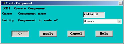
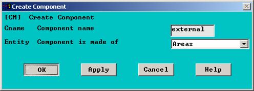
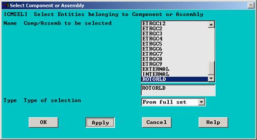
Q. Before
we apply the convection loads, let's store this group of areas in a component
for easy recall later on. In the
Utilities menu, pick Select >Comp/Assembly >Create
Component.
7.1.Q08D0C9EA79F9BACE118C8200AA004BA90B02000000080000000E0000005F005200650066003500300037003200350033003600390038000000
7.1.Q08D0C9EA79F9BACE118C8200AA004BA90B02000000080000000E0000005F005200650066003500300037003200350033003600390038000000
|
R. For
Component name, enter: rotorld.
S. Change
Component is made of to: Areas.
T. OK.
7.1.R08D0C9EA79F9BACE118C8200AA004BA90B02000000080000000E0000005F005200650066003500300037003200350034003000310034000000
7.1.R08D0C9EA79F9BACE118C8200AA004BA90B02000000080000000E0000005F005200650066003500300037003200350034003000310034000000
|
7.1.S08D0C9EA79F9BACE118C8200AA004BA90B02000000080000000E0000005F005200650066003500300037003200350034003000320032000000
7.1.S08D0C9EA79F9BACE118C8200AA004BA90B02000000080000000E0000005F005200650066003500300037003200350034003000320032000000
|
7.1.T08D0C9EA79F9BACE118C8200AA004BA90B02000000080000000E0000005F005200650066003500300037003200350034003000330032000000
7.1.T08D0C9EA79F9BACE118C8200AA004BA90B02000000080000000E0000005F005200650066003500300037003200350034003000330032000000
|
Rotor
Convection Load Application:
A. We are ready to apply the
convection load to the rotor. In the
MTB, pick the Load tab.
B. Pick
the Area Convection button.
7.2.A08D0C9EA79F9BACE118C8200AA004BA90B02000000080000000E0000005F005200650066003500300037003200350035003200370030000000
7.2.A08D0C9EA79F9BACE118C8200AA004BA90B02000000080000000E0000005F005200650066003500300037003200350035003200370030000000
|
7.2.B08D0C9EA79F9BACE118C8200AA004BA90B02000000080000000E0000005F005200650066003500300037003200350034003500320037000000
7.2.B08D0C9EA79F9BACE118C8200AA004BA90B02000000080000000E0000005F005200650066003500300037003200350034003500320037000000
|
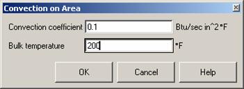
C. A
dialog will appear for you to select areas. Choose the Pick All button.
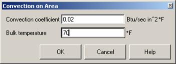
D.
 For Convection coefficient, enter: 0.1.
E. For
Bulk Temperature, enter: 200.
F. OK.
G.
7.2.E08D0C9EA79F9BACE118C8200AA004BA90B02000000080000000E0000005F005200650066003500300037003200350034003900320031000000 23323j921x
7.2.E08D0C9EA79F9BACE118C8200AA004BA90B02000000080000000E0000005F005200650066003500300037003200350034003900320031000000 23323j921x
|
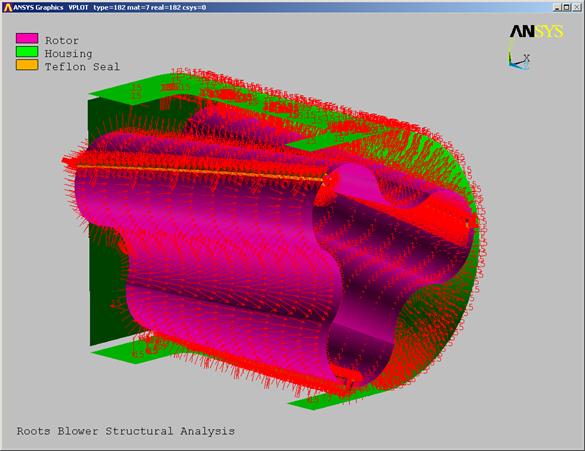
 ANSYS
will plot convection load symbols on the areas as shown below.
ANSYS
will plot convection load symbols on the areas as shown below.
7.2.D08D0C9EA79F9BACE118C8200AA004BA90B02000000080000000E0000005F005200650066003500300037003200350034003900310030000000
7.2.D08D0C9EA79F9BACE118C8200AA004BA90B02000000080000000E0000005F005200650066003500300037003200350034003900310030000000
|
7.2.C08D0C9EA79F9BACE118C8200AA004BA90B02000000080000000E0000005F005200650066003500300037003200350034003800390036000000
7.2.C08D0C9EA79F9BACE118C8200AA004BA90B02000000080000000E0000005F005200650066003500300037003200350034003800390036000000
|
7.2.F08D0C9EA79F9BACE118C8200AA004BA90B02000000080000000E0000005F005200650066003500300037003200350034003900320039000000
7.2.F08D0C9EA79F9BACE118C8200AA004BA90B02000000080000000E0000005F005200650066003500300037003200350034003900320039000000
|
7.2.G08D0C9EA79F9BACE118C8200AA004BA90B02000000080000000E0000005F005200650066003500300037003200350035003000310038000000
7.2.G08D0C9EA79F9BACE118C8200AA004BA90B02000000080000000E0000005F005200650066003500300037003200350035003000310038000000
|
Internal
Housing Surface Selection:
Next, we will
select the internal surfaces of the housing and bearing plate.
A. To
speed plotting, turn off the boundary condition symbol display. Pick the Boundary Condition button in
the MTB.
7.3.A08D0C9EA79F9BACE118C8200AA004BA90B02000000080000000E0000005F005200650066003500300037003600340035003000310030000000
7.3.A08D0C9EA79F9BACE118C8200AA004BA90B02000000080000000E0000005F005200650066003500300037003600340035003000310030000000
|
B.
7.3.B08D0C9EA79F9BACE118C8200AA004BA90B02000000080000000E0000005F005200650066003500300037003600340035003400360038000000
7.3.B08D0C9EA79F9BACE118C8200AA004BA90B02000000080000000E0000005F005200650066003500300037003600340035003400360038000000
|
 Restore
the entire model to the selected set. In
the Utility menu, pick Select >Everything.
Restore
the entire model to the selected set. In
the Utility menu, pick Select >Everything.
C. Plot
the Volumes to see the entire model again. Pick the Plot Volumes button.
7.3.C08D0C9EA79F9BACE118C8200AA004BA90B02000000080000000E0000005F005200650066003500300037003600340035003600300038000000
7.3.C08D0C9EA79F9BACE118C8200AA004BA90B02000000080000000E0000005F005200650066003500300037003600340035003600300038000000
|
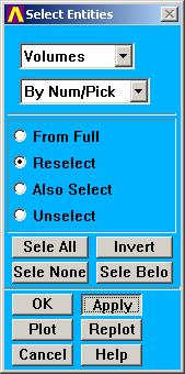
D.
In
the Utility menu, pick Select >Entities.
7.3.D08D0C9EA79F9BACE118C8200AA004BA90B02000000080000000E0000005F005200650066003500300037003600340037003200360033000000
7.3.D08D0C9EA79F9BACE118C8200AA004BA90B02000000080000000E0000005F005200650066003500300037003600340037003200360033000000
|
E. Volumes.
F. Apply.
7.3.F08D0C9EA79F9BACE118C8200AA004BA90B02000000080000000E0000005F005200650066003500300037003600340037003200380032000000
7.3.F08D0C9EA79F9BACE118C8200AA004BA90B02000000080000000E0000005F005200650066003500300037003600340037003200380032000000
|
7.3.E08D0C9EA79F9BACE118C8200AA004BA90B02000000080000000E0000005F005200650066003500300037003600340037003200370031000000 23323j921x
7.3.E08D0C9EA79F9BACE118C8200AA004BA90B02000000080000000E0000005F005200650066003500300037003600340037003200370031000000 23323j921x
|
G. A
dialog box will appear for you to select volumes. Pick the housing and bearing plate volumes as
shown in the picture below.
7.3.G08D0C9EA79F9BACE118C8200AA004BA90B02000000080000000E0000005F005200650066003500300037003600340037003500320036000000
7.3.G08D0C9EA79F9BACE118C8200AA004BA90B02000000080000000E0000005F005200650066003500300037003600340037003500320036000000
|
Bearing Plate
Bearing Plate
|
H. Pick
OK in the Select Volumes dialog.
I.
7.3.H08D0C9EA79F9BACE118C8200AA004BA90B02000000080000000E0000005F005200650066003500300037003600340037003800340033000000
7.3.H08D0C9EA79F9BACE118C8200AA004BA90B02000000080000000E0000005F005200650066003500300037003600340037003800340033000000
|
7.3.I08D0C9EA79F9BACE118C8200AA004BA90B02000000080000000E0000005F005200650066003500300037003600340037003800350031000000 23323j921x
7.3.I08D0C9EA79F9BACE118C8200AA004BA90B02000000080000000E0000005F005200650066003500300037003600340037003800350031000000 23323j921x
|
7.3.J08D0C9EA79F9BACE118C8200AA004BA90B02000000080000000E0000005F005200650066003500300037003600340038003800360035000000
7.3.J08D0C9EA79F9BACE118C8200AA004BA90B02000000080000000E0000005F005200650066003500300037003600340038003800360035000000
|
J.
7.3.K08D0C9EA79F9BACE118C8200AA004BA90B02000000080000000E0000005F005200650066003500300037003600340038003800370036000000
7.3.K08D0C9EA79F9BACE118C8200AA004BA90B02000000080000000E0000005F005200650066003500300037003600340038003800370036000000
|
 Next,
we will select the areas describing the internal surfaces of the blower. In the Select Entities dialog, change Volumes
to Areas.
Next,
we will select the areas describing the internal surfaces of the blower. In the Select Entities dialog, change Volumes
to Areas.
K. Reselect.
L. Apply.
7.3.L08D0C9EA79F9BACE118C8200AA004BA90B02000000080000000E0000005F005200650066003500310033003400370034003600300030000000
7.3.K08D0C9EA79F9BACE118C8200AA004BA90B02000000080000000E0000005F005200650066003500300037003600340038003800370036000000
|

M. A dialog will appear for you
to select areas. There are three areas
making up the internal surfaces. Pick
near the hot spots shown below. Use the
dynamic viewing controls to obtain better views. When selecting the bearing plate area, be
sure to select the inner most surface as shown below.
Bearing plate. Select the front of the bearing plate. Be careful not to select the outer
surfaces.
|
Bearing housing upper surface
Bearing housing upper surface
|
|
|
Bearing housing lower surface
Bearing housing lower surface
|
|
N.
3 areas total
5 total areas
|
|


7.3.N08D0C9EA79F9BACE118C8200AA004BA90B02000000080000000E0000005F005200650066003500300037003600350030003000390032000000
7.3.N08D0C9EA79F9BACE118C8200AA004BA90B02000000080000000E0000005F005200650066003500300037003600350030003000390032000000
|
O. In
the MTB, pick the Plot Areas fly-out.
7.3.O08D0C9EA79F9BACE118C8200AA004BA90B02000000080000000E0000005F005200650066003500300037003600350030003100300032000000
7.3.O08D0C9EA79F9BACE118C8200AA004BA90B02000000080000000E0000005F005200650066003500300037003600350030003100300032000000
|

P.
7.3.P08D0C9EA79F9BACE118C8200AA004BA90B02000000080000000E0000005F005200650066003500300037003600350030003200300030000000
7.3.P08D0C9EA79F9BACE118C8200AA004BA90B02000000080000000E0000005F005200650066003500300037003600350030003200300030000000
|
Q. As
before, we will create a component of these areas to make selecting them easier
later on. In the Utility menu, pick: Select >Comp/Assembly >Create Component.
7.3.Q08D0C9EA79F9BACE118C8200AA004BA90B02000000080000000E0000005F005200650066003500300037003600350030003400370039000000
7.3.Q08D0C9EA79F9BACE118C8200AA004BA90B02000000080000000E0000005F005200650066003500300037003600350030003400370039000000
|
R. Enter
the name internal for this component.
S. Areas.
T. OK.
Internal
Housing Convection Load Application:
A.
7.3.S08D0C9EA79F9BACE118C8200AA004BA90B02000000080000000E0000005F005200650066003500300037003600350030003800380032000000
7.3.S08D0C9EA79F9BACE118C8200AA004BA90B02000000080000000E0000005F005200650066003500300037003600350030003800380032000000
|

7.3.R08D0C9EA79F9BACE118C8200AA004BA90B02000000080000000E0000005F005200650066003500300037003600350030003800360039000000
7.3.R08D0C9EA79F9BACE118C8200AA004BA90B02000000080000000E0000005F005200650066003500300037003600350030003800360039000000
|
7.3.T08D0C9EA79F9BACE118C8200AA004BA90B02000000080000000E0000005F005200650066003500300037003600350030003800390037000000
7.3.T08D0C9EA79F9BACE118C8200AA004BA90B02000000080000000E0000005F005200650066003500300037003600350030003800390037000000
|

We
are ready to apply the convection load to these surfaces. In the MTB, pick the Area Convection
button.
7.4.A08D0C9EA79F9BACE118C8200AA004BA90B02000000080000000E0000005F005200650066003500300037003600350031003300300030000000
7.4.A08D0C9EA79F9BACE118C8200AA004BA90B02000000080000000E0000005F005200650066003500300037003600350031003300300030000000
|
B. Pick
All.
7.4.B08D0C9EA79F9BACE118C8200AA004BA90B02000000080000000E0000005F005200650066003500300037003600350031003700300033000000
7.4.B08D0C9EA79F9BACE118C8200AA004BA90B02000000080000000E0000005F005200650066003500300037003600350031003700300033000000
|
C. Enter
0.1 for the Convection Coefficient and 200 for the Bulk
Temperature.
D. OK.
7.4.C08D0C9EA79F9BACE118C8200AA004BA90B02000000080000000E0000005F005200650066003500300037003600350031003700310036000000
7.4.C08D0C9EA79F9BACE118C8200AA004BA90B02000000080000000E0000005F005200650066003500300037003600350031003700310036000000
|
7.4.D08D0C9EA79F9BACE118C8200AA004BA90B02000000080000000E0000005F005200650066003500300037003600350031003700320037000000
7.4.D08D0C9EA79F9BACE118C8200AA004BA90B02000000080000000E0000005F005200650066003500300037003600350031003700320037000000
|
E.
Your
graphics window should look like the one below.
7.4.E08D0C9EA79F9BACE118C8200AA004BA90B02000000080000000E0000005F005200650066003500300037003600350031003800380039000000
7.4.E08D0C9EA79F9BACE118C8200AA004BA90B02000000080000000E0000005F005200650066003500300037003600350031003800380039000000
|
External
Housing Surface Selection.
There are many
surfaces comprising the external housing, which would make it very difficult to
select them. It will be easier to select
all surfaces on the housing, then to unselect the ones we don't want.
A. 
7.5.A08D0C9EA79F9BACE118C8200AA004BA90B02000000080000000E0000005F005200650066003500300037003600350033003000330031000000 23323j921x
7.5.A08D0C9EA79F9BACE118C8200AA004BA90B02000000080000000E0000005F005200650066003500300037003600350033003000330031000000 23323j921x
|
In
the Utility menu, pick Select >Entities.
B.
7.5.B08D0C9EA79F9BACE118C8200AA004BA90B02000000080000000E0000005F005200650066003500300037003600350034003300340038000000
7.5.B08D0C9EA79F9BACE118C8200AA004BA90B02000000080000000E0000005F005200650066003500300037003600350034003300340038000000
|
C. Apply.
D. Pick the housing volume as
shown below.
E. OK.
7.5.C08D0C9EA79F9BACE118C8200AA004BA90B02000000080000000E0000005F005200650066003500300037003600350034003300360033000000
7.5.C08D0C9EA79F9BACE118C8200AA004BA90B02000000080000000E0000005F005200650066003500300037003600350034003300360033000000
|
7.5.D08D0C9EA79F9BACE118C8200AA004BA90B02000000080000000E0000005F005200650066003500300037003600350034003300380036000000
7.5.D08D0C9EA79F9BACE118C8200AA004BA90B02000000080000000E0000005F005200650066003500300037003600350034003300380036000000
|
7.5.E08D0C9EA79F9BACE118C8200AA004BA90B02000000080000000E0000005F005200650066003500300037003600350034003400300034000000
7.5.E08D0C9EA79F9BACE118C8200AA004BA90B02000000080000000E0000005F005200650066003500300037003600350034003400300034000000
|
F. Aain
select all entities below the selected volume. Change Entity type to Volumes.
G. Sele
Belo.
H. Replot.
I.
7.5.F08D0C9EA79F9BACE118C8200AA004BA90B02000000080000000E0000005F005200650066003500300037003600350033003400330039000000
7.5.F08D0C9EA79F9BACE118C8200AA004BA90B02000000080000000E0000005F005200650066003500300037003600350033003400330039000000
|

7.5.G08D0C9EA79F9BACE118C8200AA004BA90B02000000080000000E0000005F005200650066003500300037003600350033003400350031000000 23323j921x
7.5.G08D0C9EA79F9BACE118C8200AA004BA90B02000000080000000E0000005F005200650066003500300037003600350033003400350031000000 23323j921x
|
7.5.H08D0C9EA79F9BACE118C8200AA004BA90B02000000080000000E0000005F005200650066003500300037003600350033003400360033000000
7.5.H08D0C9EA79F9BACE118C8200AA004BA90B02000000080000000E0000005F005200650066003500300037003600350033003400360033000000
|
7.5.I08D0C9EA79F9BACE118C8200AA004BA90B02000000080000000E0000005F005200650066003500300037003600350033003600330039000000
7.5.I08D0C9EA79F9BACE118C8200AA004BA90B02000000080000000E0000005F005200650066003500300037003600350033003600330039000000
|
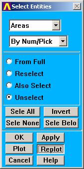
J. We
will begin by unselecting the internal surfaces. In the Select Entities dialog, change Volumes
back to Areas.
K.
7.5.L08D0C9EA79F9BACE118C8200AA004BA90B02000000080000000E0000005F005200650066003500300037003600350034003800350033000000
7.5.L08D0C9EA79F9BACE118C8200AA004BA90B02000000080000000E0000005F005200650066003500300037003600350034003800350033000000
|

7.5.K08D0C9EA79F9BACE118C8200AA004BA90B02000000080000000E0000005F005200650066003500300037003600350034003800340031000000 23323j921x
7.5.K08D0C9EA79F9BACE118C8200AA004BA90B02000000080000000E0000005F005200650066003500300037003600350034003800340031000000 23323j921x
|

7.5.J08D0C9EA79F9BACE118C8200AA004BA90B02000000080000000E0000005F005200650066003500300037003600350034003800320036000000
7.5.J08D0C9EA79F9BACE118C8200AA004BA90B02000000080000000E0000005F005200650066003500300037003600350034003800320036000000
|
 Unselect.
L. Apply.

M. A
dialog will appear for you to select areas. Pick the three internal surfaces to start with as shown below. Use the dynamic viewing controls to obtain
the best view during this process. Pick OK.
7.5.M08D0C9EA79F9BACE118C8200AA004BA90B02000000080000000E0000005F005200650066003500300037003600350035003500350030000000
7.5.M08D0C9EA79F9BACE118C8200AA004BA90B02000000080000000E0000005F005200650066003500300037003600350035003500350030000000
|
Bearing housing upper surface
Bearing housing upper surface
|
Bearing housing lower surface
Bearing housing lower surface
|
N.
 In the Select Entities dialog, pick the Replot
button. Your plot should look like the
one below.
In the Select Entities dialog, pick the Replot
button. Your plot should look like the
one below.
O. Pick
the Apply button again to unselect more areas.
7.5.N08D0C9EA79F9BACE118C8200AA004BA90B02000000080000000E0000005F005200650066003500300037003600350039003200360034000000
7.5.N08D0C9EA79F9BACE118C8200AA004BA90B02000000080000000E0000005F005200650066003500300037003600350039003200360034000000
|
7.5.O08D0C9EA79F9BACE118C8200AA004BA90B02000000080000000E0000005F005200650066003500300037003600350039003500320037000000
7.5.O08D0C9EA79F9BACE118C8200AA004BA90B02000000080000000E0000005F005200650066003500300037003600350039003500320037000000
|
P. Pick
the surfaces on the symmetry cut planes of the housing and the holes as shown
in the two views below. There will be
two areas for each hole. You should pick
18 areas total.
7.5.P08D0C9EA79F9BACE118C8200AA004BA90B02000000080000000E0000005F005200650066003500300037003600360031003500340038000000
7.5.P08D0C9EA79F9BACE118C8200AA004BA90B02000000080000000E0000005F005200650066003500300037003600360031003500340038000000
|
7.5.P08D0C9EA79F9BACE118C8200AA004BA90B02000000080000000E0000005F005200650066003500300037003600360031003500340038000000
7.5.P08D0C9EA79F9BACE118C8200AA004BA90B02000000080000000E0000005F005200650066003500300037003600360031003500340038000000
|
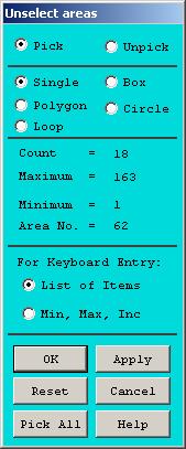
Q. Make
sure there are 18 areas selected. OK.
7.5.Q08D0C9EA79F9BACE118C8200AA004BA90B02000000080000000E0000005F005200650066003500300037003600360031003600320030000000
7.5.Q08D0C9EA79F9BACE118C8200AA004BA90B02000000080000000E0000005F005200650066003500300037003600360031003600320030000000
|
R.
7.5.R08D0C9EA79F9BACE118C8200AA004BA90B02000000080000000E0000005F005200650066003500300037003600360031003800350030000000
7.5.R08D0C9EA79F9BACE118C8200AA004BA90B02000000080000000E0000005F005200650066003500300037003600360031003800350030000000
|

Pick
the Replot button. Your plot
should look like the one below:
S. Store
this selection of areas as another component. In the Utility menu, pick Select >Comp/Assembly >Create
Component.
T.
7.5.S08D0C9EA79F9BACE118C8200AA004BA90B02000000080000000E0000005F005200650066003500300037003600360032003300310036000000
7.5.S08D0C9EA79F9BACE118C8200AA004BA90B02000000080000000E0000005F005200650066003500300037003600360032003300310036000000
|
U. OK.
7.5.T08D0C9EA79F9BACE118C8200AA004BA90B02000000080000000E0000005F005200650066003500300037003600360032003300320037000000
7.5.T08D0C9EA79F9BACE118C8200AA004BA90B02000000080000000E0000005F005200650066003500300037003600360032003300320037000000
|
7.5.U08D0C9EA79F9BACE118C8200AA004BA90B02000000080000000E0000005F005200650066003500300037003600360032003300340030000000
7.5.U08D0C9EA79F9BACE118C8200AA004BA90B02000000080000000E0000005F005200650066003500300037003600360032003300340030000000
|
External
Housing Convection Load Application:
A. We
are ready to apply the convection load to these surfaces. In the MTB, pick the Area Convection
button.
7.6.A08D0C9EA79F9BACE118C8200AA004BA90B02000000080000000E0000005F005200650066003500300037003600360032003900300038000000
7.6.A08D0C9EA79F9BACE118C8200AA004BA90B02000000080000000E0000005F005200650066003500300037003600360032003900300038000000
|
B. Pick
All.
C.
Enter
0.02 for the Convection coefficient and 70 for the Bulk
temperature.
D. OK.
7.6.C08D0C9EA79F9BACE118C8200AA004BA90B02000000080000000E0000005F005200650066003500300037003600360032003900330034000000
7.6.C08D0C9EA79F9BACE118C8200AA004BA90B02000000080000000E0000005F005200650066003500300037003600360032003900330034000000
|
7.6.D08D0C9EA79F9BACE118C8200AA004BA90B02000000080000000E0000005F005200650066003500300037003600360032003900340033000000
7.6.D08D0C9EA79F9BACE118C8200AA004BA90B02000000080000000E0000005F005200650066003500300037003600360032003900340033000000
|
7.6.B08D0C9EA79F9BACE118C8200AA004BA90B02000000080000000E0000005F005200650066003500300037003600360032003900310038000000
7.6.B08D0C9EA79F9BACE118C8200AA004BA90B02000000080000000E0000005F005200650066003500300037003600360032003900310038000000
|
E.
7.6.E08D0C9EA79F9BACE118C8200AA004BA90B02000000080000000E0000005F005200650066003500300037003600360033003100320031000000 23323j921x
7.6.E08D0C9EA79F9BACE118C8200AA004BA90B02000000080000000E0000005F005200650066003500300037003600360033003100320031000000 23323j921x
|
F. We
have completed the boundary condition application for the thermal
analysis. Before we proceed, let's
restore all entities to the selected set. In the Utility menu, pick Select >Everything.
7.6.F08D0C9EA79F9BACE118C8200AA004BA90B02000000080000000E0000005F005200650066003500300037003600360033003500310033000000
7.6.F08D0C9EA79F9BACE118C8200AA004BA90B02000000080000000E0000005F005200650066003500300037003600360033003500310033000000
|
Thermal
Solution:
Save
Database.
A. We
are now ready to perform the thermal solution. Let's save our work before we do so. In the MTB, pick the Save button. Enter a name for the model and pick OK
in the dialog that appears.
8.1.A08D0C9EA79F9BACE118C8200AA004BA90B02000000080000000E0000005F005200650066003500300037003600360036003400370035000000
8.1.A08D0C9EA79F9BACE118C8200AA004BA90B02000000080000000E0000005F005200650066003500300037003600360036003400370035000000
|
Solve.
A. Pick
the Solve tab in the MTB
8.2.A08D0C9EA79F9BACE118C8200AA004BA90B02000000080000000E0000005F005200650066003500300037003600360036003400380037000000
8.2.A08D0C9EA79F9BACE118C8200AA004BA90B02000000080000000E0000005F005200650066003500300037003600360036003400380037000000
|
B. Pick
the Solve Problem button.
8.2.B08D0C9EA79F9BACE118C8200AA004BA90B02000000080000000E0000005F005200650066003500300037003600360036003400390039000000
8.2.B08D0C9EA79F9BACE118C8200AA004BA90B02000000080000000E0000005F005200650066003500300037003600360036003400390039000000
|
C. Pick
OK in the confirmation dialog box. Note: You may have told ANSYS not to show this prompt again in a
previous session.
8.2.C08D0C9EA79F9BACE118C8200AA004BA90B02000000080000000E0000005F005200650066003500300037003600380031003600390038000000
8.2.C08D0C9EA79F9BACE118C8200AA004BA90B02000000080000000E0000005F005200650066003500300037003600380031003600390038000000
|
D. When the solution is finished, a listing will
appear showing the min and max temperature values on the model. Close this window when you are through
looking at it.
8.2.D08D0C9EA79F9BACE118C8200AA004BA90B02000000080000000E0000005F005200650066003500300037003600380034003300350030000000
008D0C9EA79F9BACE118C8200AA004BA90B02000000080000000E0000005F005200650066003400390039003500350033003000300039000000
8.2.D08D0C9EA79F9BACE118C8200AA004BA90B02000000080000000E0000005F005200650066003500300037003600380034003300350030000000
008D0C9EA79F9BACE118C8200AA004BA90B02000000080000000E0000005F005200650066003400390039003500350033003000300039000000
|
E. A temperature plot will also
be displayed in the graphics window.
8.2.E08D0C9EA79F9BACE118C8200AA004BA90B02000000080000000E0000005F005200650066003500300037003600380034003500300034000000
008D0C9EA79F9BACE118C8200AA004BA90B02000000080000000E0000005F005200650066003400390039003500350033003000300039000000
8.2.E08D0C9EA79F9BACE118C8200AA004BA90B02000000080000000E0000005F005200650066003500300037003600380034003500300034000000
008D0C9EA79F9BACE118C8200AA004BA90B02000000080000000E0000005F005200650066003400390039003500350033003000300039000000
|
|
|
Note that the thermal contact elements produced a
constant thermal gradient between the inner surface of the bearing plate
and the outer surface of the housing.
|
|
Thermal Results Post
Processing:
Temperature Plots.
A.
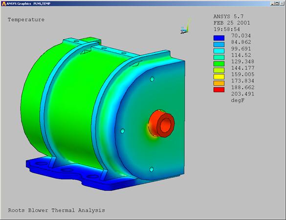
Use the dynamic viewing controls to
view all sides of the model.
9.1.A08D0C9EA79F9BACE118C8200AA004BA90B02000000080000000E0000005F005200650066003500300037003600380035003000300032000000
008D0C9EA79F9BACE118C8200AA004BA90B02000000080000000E0000005F005200650066003400390039003500350033003000300039000000
9.1.A08D0C9EA79F9BACE118C8200AA004BA90B02000000080000000E0000005F005200650066003500300037003600380035003000300032000000
008D0C9EA79F9BACE118C8200AA004BA90B02000000080000000E0000005F005200650066003400390039003500350033003000300039000000
|
B. When finished scrutinizing
the results, return the view to a suitable orientation for a report generation.
9.1.B08D0C9EA79F9BACE118C8200AA004BA90B02000000080000000E0000005F005200650066003500300037003600380035003100350035000000
008D0C9EA79F9BACE118C8200AA004BA90B02000000080000000E0000005F005200650066003400390039003500350033003000300039000000
9.1.B08D0C9EA79F9BACE118C8200AA004BA90B02000000080000000E0000005F005200650066003500300037003600380035003100350035000000
008D0C9EA79F9BACE118C8200AA004BA90B02000000080000000E0000005F005200650066003400390039003500350033003000300039000000
|
C. In the MTB, pick the Show
Report button.

9.1.C08D0C9EA79F9BACE118C8200AA004BA90B02000000080000000E0000005F005200650066003500300037003600380037003000380031000000 23323j921x
008D0C9EA79F9BACE118C8200AA004BA90B02000000080000000E0000005F005200650066003400390039003500350033003000300039000000
9.1.C08D0C9EA79F9BACE118C8200AA004BA90B02000000080000000E0000005F005200650066003500300037003600380037003000380031000000 23323j921x
008D0C9EA79F9BACE118C8200AA004BA90B02000000080000000E0000005F005200650066003400390039003500350033003000300039000000
|
D. Highlight: Create a new report.
E. General Report.
F. OK.
9.1.D08D0C9EA79F9BACE118C8200AA004BA90B02000000080000000E0000005F005200650066003500300037003600380037003300310031000000 23323j921x
008D0C9EA79F9BACE118C8200AA004BA90B02000000080000000E0000005F005200650066003400390039003500350033003000300039000000
9.1.D08D0C9EA79F9BACE118C8200AA004BA90B02000000080000000E0000005F005200650066003500300037003600380037003300310031000000 23323j921x
008D0C9EA79F9BACE118C8200AA004BA90B02000000080000000E0000005F005200650066003400390039003500350033003000300039000000
|
9.1.F08D0C9EA79F9BACE118C8200AA004BA90B02000000080000000E0000005F005200650066003500300037003600380037003300330031000000 23323j921x
008D0C9EA79F9BACE118C8200AA004BA90B02000000080000000E0000005F005200650066003400390039003500350033003000300039000000
9.1.F08D0C9EA79F9BACE118C8200AA004BA90B02000000080000000E0000005F005200650066003500300037003600380037003300330031000000 23323j921x
008D0C9EA79F9BACE118C8200AA004BA90B02000000080000000E0000005F005200650066003400390039003500350033003000300039000000
|
9.1.E08D0C9EA79F9BACE118C8200AA004BA90B02000000080000000E0000005F005200650066003500300037003600380037003300320032000000
008D0C9EA79F9BACE118C8200AA004BA90B02000000080000000E0000005F005200650066003400390039003500350033003000300039000000
9.1.E08D0C9EA79F9BACE118C8200AA004BA90B02000000080000000E0000005F005200650066003500300037003600380037003300320032000000
008D0C9EA79F9BACE118C8200AA004BA90B02000000080000000E0000005F005200650066003400390039003500350033003000300039000000
|
G. ANSYS will generate an HTML
report summarizing your model and the results. When finished, the report will be launched in your default Browser. Click on the image below for a sample report. Close the report when you are finished
viewing it.
9.1.G08D0C9EA79F9BACE118C8200AA004BA90B02000000080000000E0000005F005200650066003500300037003600380037003500310037000000
008D0C9EA79F9BACE118C8200AA004BA90B02000000080000000E0000005F005200650066003400390039003500350033003000300039000000
9.1.G08D0C9EA79F9BACE118C8200AA004BA90B02000000080000000E0000005F005200650066003500300037003600380037003500310037000000
008D0C9EA79F9BACE118C8200AA004BA90B02000000080000000E0000005F005200650066003400390039003500350033003000300039000000
|
Structural Analysis:
We are now ready to do the structural analysis. We will return to the Setup tab, convert the
model from a thermal to a structural analysis, add/modify contact elements,
apply thermal loads from the previous analysis, and add structural loads and
BC's.
Structural Model Setup.
A. In the MTB, pick the Setup
tab.
B. Change the analysis type
from Thermal to Structural.
10.1.B08D0C9EA79F9BACE118C8200AA004BA90B02000000080000000E0000005F005200650066003500300037003700330035003800340032000000
008D0C9EA79F9BACE118C8200AA004BA90B02000000080000000E0000005F005200650066003400390039003500350033003000300039000000
10.1.B08D0C9EA79F9BACE118C8200AA004BA90B02000000080000000E0000005F005200650066003500300037003700330035003800340032000000
008D0C9EA79F9BACE118C8200AA004BA90B02000000080000000E0000005F005200650066003400390039003500350033003000300039000000
|
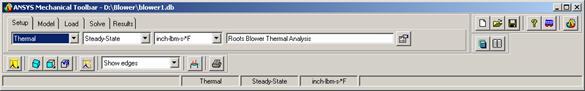
10.1.A08D0C9EA79F9BACE118C8200AA004BA90B02000000080000000E0000005F005200650066003500300037003700330035003800330030000000
008D0C9EA79F9BACE118C8200AA004BA90B02000000080000000E0000005F005200650066003400390039003500350033003000300039000000
10.1.A08D0C9EA79F9BACE118C8200AA004BA90B02000000080000000E0000005F005200650066003500300037003700330035003800330030000000
008D0C9EA79F9BACE118C8200AA004BA90B02000000080000000E0000005F005200650066003400390039003500350033003000300039000000
|
C. ANSYS will put you into the
Load menu. Pick the Setup tab again.
10.1.C08D0C9EA79F9BACE118C8200AA004BA90B02000000080000000E0000005F005200650066003500300037003700330035003900340032000000
008D0C9EA79F9BACE118C8200AA004BA90B02000000080000000E0000005F005200650066003400390039003500350033003000300039000000
10.1.C08D0C9EA79F9BACE118C8200AA004BA90B02000000080000000E0000005F005200650066003500300037003700330035003900340032000000
008D0C9EA79F9BACE118C8200AA004BA90B02000000080000000E0000005F005200650066003400390039003500350033003000300039000000
|
D. Change the title to Roots
Blower Structural Analysis.
10.1.D08D0C9EA79F9BACE118C8200AA004BA90B02000000080000000E0000005F005200650066003500300037003700330036003500350031000000 23323j921x
008D0C9EA79F9BACE118C8200AA004BA90B02000000080000000E0000005F005200650066003400390039003500350033003000300039000000
10.1.D08D0C9EA79F9BACE118C8200AA004BA90B02000000080000000E0000005F005200650066003500300037003700330036003500350031000000 23323j921x
008D0C9EA79F9BACE118C8200AA004BA90B02000000080000000E0000005F005200650066003400390039003500350033003000300039000000
|
Structural
Contact Element Definition
A. Pick
the Model tab.
10.2.A08D0C9EA79F9BACE118C8200AA004BA90B02000000080000000E0000005F005200650066003500300037003700360039003300380030000000
008D0C9EA79F9BACE118C8200AA004BA90B02000000080000000E0000005F005200650066003400390039003500350033003000300039000000
10.208D0C9EA79F9BACE118C8200AA004BA90B02000000080000000E0000005F005200650066003500300037003700330036003500360030000000
008D0C9EA79F9BACE118C8200AA004BA90B02000000080000000E0000005F005200650066003400390039003500350033003000300039000000
|
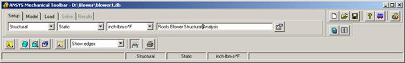
B. Pick the View/Modify
Contact button.
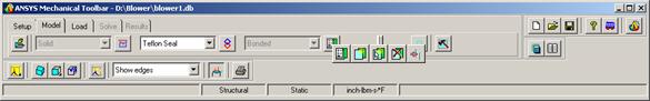
10.2.B08D0C9EA79F9BACE118C8200AA004BA90B02000000080000000E0000005F005200650066003500300037003700360037003400350034000000
008D0C9EA79F9BACE118C8200AA004BA90B02000000080000000E0000005F005200650066003400390039003500350033003000300039000000
Error!
Reference source not found.
008D0C9EA79F9BACE118C8200AA004BA90B02000000080000000E0000005F005200650066003400390039003500350033003000300039000000
|
We need to review all contact surfaces again to make sure
they have the appropriate behavior. We
want all surfaces to behave as frictionless (no separation) except the contact
between the Teflon seals and the rotor slots, which will be bonded.
C.

10.2.C08D0C9EA79F9BACE118C8200AA004BA90B02000000080000000E0000005F005200650066003500300037003700360038003200360036000000
008D0C9EA79F9BACE118C8200AA004BA90B02000000080000000E0000005F005200650066003400390039003500350033003000300039000000
Error!
Reference source not found.
008D0C9EA79F9BACE118C8200AA004BA90B02000000080000000E0000005F005200650066003400390039003500350033003000300039000000
|

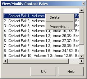 In
the View/Modify Contact Pairs dialog, pick each pair and determine it's
behavior. The first one you should
change is Contact Pair 1: When it
is highlighted, click the right mouse button until the option menu
appears. Then pick the Properties
button.
In
the View/Modify Contact Pairs dialog, pick each pair and determine it's
behavior. The first one you should
change is Contact Pair 1: When it
is highlighted, click the right mouse button until the option menu
appears. Then pick the Properties
button.
D. Contact Pair 1 is one is
between the housing back face and the bearing plate.
10.2.D08D0C9EA79F9BACE118C8200AA004BA90B02000000080000000E0000005F005200650066003500300037003700360038003200370033000000
008D0C9EA79F9BACE118C8200AA004BA90B02000000080000000E0000005F005200650066003400390039003500350033003000300039000000
Error!
Reference source not found.
008D0C9EA79F9BACE118C8200AA004BA90B02000000080000000E0000005F005200650066003400390039003500350033003000300039000000
|
E. Pick the Bonded
button.
F.
10.2.E08D0C9EA79F9BACE118C8200AA004BA90B02000000080000000E0000005F005200650066003500300037003700360038003400390033000000
008D0C9EA79F9BACE118C8200AA004BA90B02000000080000000E0000005F005200650066003400390039003500350033003000300039000000
Error!
Reference source not found.
008D0C9EA79F9BACE118C8200AA004BA90B02000000080000000E0000005F005200650066003400390039003500350033003000300039000000
|

10.2.F08D0C9EA79F9BACE118C8200AA004BA90B02000000080000000E0000005F005200650066003500300037003700360038003400390039000000
008D0C9EA79F9BACE118C8200AA004BA90B02000000080000000E0000005F005200650066003400390039003500350033003000300039000000
Error!
Reference source not found.
008D0C9EA79F9BACE118C8200AA004BA90B02000000080000000E0000005F005200650066003400390039003500350033003000300039000000
|
OK.
G. Continue checking each
contact pair. When finished, review your
changes with the table below:
|
10.2.G08D0C9EA79F9BACE118C8200AA004BA90B02000000080000000E0000005F005200650066003500300037003700370030003100360031000000 23323j921x
008D0C9EA79F9BACE118C8200AA004BA90B02000000080000000E0000005F005200650066003400390039003500350033003000300039000000
Error!
Reference source not found.
008D0C9EA79F9BACE118C8200AA004BA90B02000000080000000E0000005F005200650066003400390039003500350033003000300039000000
|
 Contact Pair: Contact Pair:
|
Contact Behavior:
|
|
Contact Pair 1
|
Frictionless (No Separation)
|
|
Contact Pair 2
|
Bonded
|
|
Contact Pair 3
|
Bonded
|
|
Contact Pair 4
|
Frictionless (No Separation)
|
|
Contact Pair 5
|
Bonded
|
|
Contact Pair 6
|
Bonded
|
|
Contact Pair 7
|
Bonded
|
|
Contact Pair 8
|
Bonded
|
|
Contact Pair 10
|
Bonded
|
|
Contact Pair 11
|
Frictionless (No Separation)
|
|
Contact Pair 12
|
Bonded
|
|
Contact Pair 13
|
Bonded
|
H. When finished verifying the
contact behavior, pick OK to close the View/Modify Contact Pairs dialog.
10.2.H08D0C9EA79F9BACE118C8200AA004BA90B02000000080000000E0000005F005200650066003500300037003700370030003300310034000000
008D0C9EA79F9BACE118C8200AA004BA90B02000000080000000E0000005F005200650066003400390039003500350033003000300039000000
Error!
Reference source not found.
008D0C9EA79F9BACE118C8200AA004BA90B02000000080000000E0000005F005200650066003400390039003500350033003000300039000000
|
Add contact.
Next we will manually add two contact pairs. These will be between the outer surfaces of
the Teflon seals and the inner surface of the housing. These surfaces have a build clearance and
thus were not originally created due to the tight clearance used during the
auto-create step.
A. In the MTB, Change the
default contact behavior from Bonded to Frictionless (No Separation).
10.3.A08D0C9EA79F9BACE118C8200AA004BA90B02000000080000000E0000005F005200650066003500300037003700370031003000320034000000
|
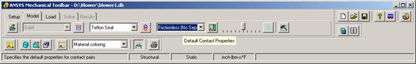
B. It
will be easier to select surfaces if we are in a line plot. Use the plot fly-out to select a Line Plot.
10.3.B08D0C9EA79F9BACE118C8200AA004BA90B02000000080000000E0000005F005200650066003500300037003700370031003700300034000000
|
C. Pick
the Fly-out option for Manually Create Contact.
10.3.C08D0C9EA79F9BACE118C8200AA004BA90B02000000080000000E0000005F005200650066003500300037003700370031003700360039000000
|
D.
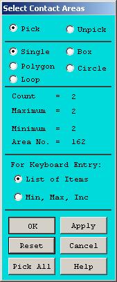
10.3.D08D0C9EA79F9BACE118C8200AA004BA90B02000000080000000E0000005F005200650066003500300037003700370032003100360037000000
|


Use the dynamic viewing controls to
help you select the lower seal outer tip and the case inner housing as shown
below.
E. Pick Apply to create
the contact pair.
10.3.E08D0C9EA79F9BACE118C8200AA004BA90B02000000080000000E0000005F005200650066003500300037003700370032003300310035000000
|
F.
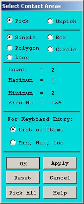
10.3.F08D0C9EA79F9BACE118C8200AA004BA90B02000000080000000E0000005F005200650066003500300037003700370032003600380033000000
|


Pick the Housing inner surface and the
other Seal slot for the last pair.
G. OK.
10.3.G08D0C9EA79F9BACE118C8200AA004BA90B02000000080000000E0000005F005200650066003500300037003700370032003600390030000000
|
Structural Loads and BC's:
Pressure loads.
A.
11.1.A08D0C9EA79F9BACE118C8200AA004BA90B02000000080000000E0000005F005200650066003500300037003700370033003000360037000000
|
 Next, we will apply a 15 PSI pressure load
on all internal surfaces. We will first
select the rotorld and internal components we defined previously. Pick: Select >Comp/Assembly >Select Comp/Assembly.
Next, we will apply a 15 PSI pressure load
on all internal surfaces. We will first
select the rotorld and internal components we defined previously. Pick: Select >Comp/Assembly >Select Comp/Assembly.
B.
You will see several additional
components you didn't create. These are
working components created by the auto-contact feature. Pick the ROTORLD component.
C.
11.1.B08D0C9EA79F9BACE118C8200AA004BA90B02000000080000000E0000005F005200650066003500300037003700370033003200390037000000
|
11.1.C08D0C9EA79F9BACE118C8200AA004BA90B02000000080000000E0000005F005200650066003500300037003700370033003300300032000000
|
 Apply.
D. Pick: INTERNAL from the list.
E. Change Type of selection to Also
select.
F. OK.
G. In the MTB, pick the Material
coloring, and Redraw Model buttons to view the selected set.
11.1.G08D0C9EA79F9BACE118C8200AA004BA90B02000000080000000E0000005F005200650066003500300037003700370034003000340036000000
|
11.1.F08D0C9EA79F9BACE118C8200AA004BA90B02000000080000000E0000005F005200650066003500300037003700370033003500380035000000
|
11.1.D08D0C9EA79F9BACE118C8200AA004BA90B02000000080000000E0000005F005200650066003500300037003700370033003500370033000000
|
11.1.E08D0C9EA79F9BACE118C8200AA004BA90B02000000080000000E0000005F005200650066003500300037003700370033003500370038000000
|
H. Use the dynamic viewing
controls to view your selected set. It
should look like the plot below:
11.1.H08D0C9EA79F9BACE118C8200AA004BA90B02000000080000000E0000005F005200650066003500300037003700370034003100350037000000
|
I. We are ready to apply the
pressure load. Pick the Load tab
in the MTB.
11.1.I08D0C9EA79F9BACE118C8200AA004BA90B02000000080000000E0000005F005200650066003500300037003700370034003200380032000000
|
J. Pick the Area Pressure
button.
11.1.J08D0C9EA79F9BACE118C8200AA004BA90B02000000080000000E0000005F005200650066003500300037003700370034003600310038000000
|
K. Pick All.
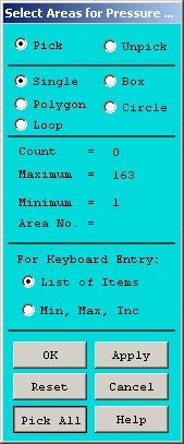
11.1.K08D0C9EA79F9BACE118C8200AA004BA90B02000000080000000E0000005F005200650066003500300037003700370034003600380031000000 23323j921x
|
L. Enter 15 for the
pressure.
M. OK.
11.1.L08D0C9EA79F9BACE118C8200AA004BA90B02000000080000000E0000005F005200650066003500300037003700370034003800310039000000
|
11.1.M08D0C9EA79F9BACE118C8200AA004BA90B02000000080000000E0000005F005200650066003500300037003700370034003800320035000000
|
N. Pressure load symbols will
be displayed on your model.
11.1.N08D0C9EA79F9BACE118C8200AA004BA90B02000000080000000E0000005F005200650066003500300037003700370034003900310037000000
|
O.
11.1.O08D0C9EA79F9BACE118C8200AA004BA90B02000000080000000E0000005F005200650066003500300037003700370035003100320039000000
|
Restore the entire model to the
selected set. In the Utility menu, pick Select >Everything.
P.
11.1.P08D0C9EA79F9BACE118C8200AA004BA90B02000000080000000E0000005F005200650066003500300037003700370035003300390033000000
|
 Pick
the Boundary Conditions button to turn off the pressure load symbols.
Pick
the Boundary Conditions button to turn off the pressure load symbols.
Q. The entire model will be
redrawn.
Body Loads:
A. We are ready to apply the
temperature and centrifugal loading. In
the MTB, pick the Body Load button.
11.2.A08D0C9EA79F9BACE118C8200AA004BA90B02000000080000000E0000005F005200650066003500300037003700370035003600350035000000
|
11.1.Q08D0C9EA79F9BACE118C8200AA004BA90B02000000080000000E0000005F005200650066003500300037003700370035003400360034000000
|
B.
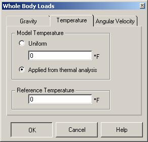
11.2.B08D0C9EA79F9BACE118C8200AA004BA90B02000000080000000E0000005F005200650066003500300037003700370036003000370033000000
|
C.
11.2.C08D0C9EA79F9BACE118C8200AA004BA90B02000000080000000E0000005F005200650066003500300037003700370036003000370039000000
|
D. OK.
E. Highlight the file Environment_1.rth.
F.
11.2.D08D0C9EA79F9BACE118C8200AA004BA90B02000000080000000E0000005F005200650066003500300037003700370036003000380036000000
|
11.2.E08D0C9EA79F9BACE118C8200AA004BA90B02000000080000000E0000005F005200650066003500300037003700370036003300370030000000
|
11.2.F08D0C9EA79F9BACE118C8200AA004BA90B02000000080000000E0000005F005200650066003500300037003700370036003300370039000000
|
G. Pick the Body Load
button again.
11.2.G08D0C9EA79F9BACE118C8200AA004BA90B02000000080000000E0000005F005200650066003500300037003700370036003700350036000000
|
H. Pick the Angular Velocity
tab.
I. Enter 14000 for about
the Z-axis.
J. OK.
11.2.J08D0C9EA79F9BACE118C8200AA004BA90B02000000080000000E0000005F005200650066003500300037003700370036003900330037000000
|
11.2.H08D0C9EA79F9BACE118C8200AA004BA90B02000000080000000E0000005F005200650066003500300037003700370036003900320030000000
|
11.2.I08D0C9EA79F9BACE118C8200AA004BA90B02000000080000000E0000005F005200650066003500300037003700370036003900330030000000
|
Symmetry BC's.
A. Pick the Model Symmetry
button in the MTB.
11.3.A08D0C9EA79F9BACE118C8200AA004BA90B02000000080000000E0000005F005200650066003500300037003700370037003300340037000000
|
B.
Since this is a quarter symmetry
model, we will apply symmetry BC's on the two cut planes of the model, and also
the bottom of the housing, which is bolted to the engine. Pick the symmetry faces shown in the plot
below. (The arrows are not
necessarily at the hot spots for picking).
11.3.B08D0C9EA79F9BACE118C8200AA004BA90B02000000080000000E0000005F005200650066003500300037003700370037003300360033000000
|
C. The graphics window will
redraw showing symmetry symbols.
11.3.C08D0C9EA79F9BACE118C8200AA004BA90B02000000080000000E0000005F005200650066003500300037003700370037003600380030000000
|
D. We have completed the
modeling task and are ready for solution. Pick the Save Model button to save our work before proceeding.
Structural Model Solution:
Solve.
A. Pick the Solve tab in
the MTB.
12.1.A08D0C9EA79F9BACE118C8200AA004BA90B02000000080000000E0000005F005200650066003500300037003700370037003900390037000000
|
B. Pick the Solve Now
button.
12.1.B08D0C9EA79F9BACE118C8200AA004BA90B02000000080000000E0000005F005200650066003500300037003700370038003100300033000000
|
11.3.D08D0C9EA79F9BACE118C8200AA004BA90B02000000080000000E0000005F005200650066003500300037003700370037003800320039000000
|
C. Pick OK in the
confirmation window. Note: This window may not appear if you told ANSYS
not to show the prompt again in a previous session.
12.1.C08D0C9EA79F9BACE118C8200AA004BA90B02000000080000000E0000005F005200650066003500300037003800310038003700340035000000
|
D. The solution may take
several minutes. When finished, a window
will appear showing the min and max displacements and stress values. When you are through looking at this window, close
it.
12.1.D08D0C9EA79F9BACE118C8200AA004BA90B02000000080000000E0000005F005200650066003500300037003800310038003700350033000000
|
E. ANSYS will plot the Von
Mises stress in the graphics window.
12.1.E08D0C9EA79F9BACE118C8200AA004BA90B02000000080000000E0000005F005200650066003500300037003800310038003800340036000000
|
Post Processing:
Stress Plots.
A. The Results Tab will now be
activated in the MTB. Change the Results
Item from Equivalent Stress to 1st Principal.
13.1.A08D0C9EA79F9BACE118C8200AA004BA90B02000000080000000E0000005F005200650066003400390039003800300036003400370038000000
13.1.A08D0C9EA79F9BACE118C8200AA004BA90B02000000080000000E0000005F005200650066003400390039003800300036003400370038000000
13.1.A08D0C9EA79F9BACE118C8200AA004BA90B02000000080000000E0000005F005200650066003400390039003800300036003400370038000000
13.1.A08D0C9EA79F9BACE118C8200AA004BA90B02000000080000000E0000005F005200650066003400390039003800300036003400370038000000
|

B. Pick the Plot Result
button.
13.1.B08D0C9EA79F9BACE118C8200AA004BA90B02000000080000000E0000005F005200650066003400390039003800300036003400380034000000
13.1.B08D0C9EA79F9BACE118C8200AA004BA90B02000000080000000E0000005F005200650066003400390039003800300036003400380034000000
13.1.B08D0C9EA79F9BACE118C8200AA004BA90B02000000080000000E0000005F005200650066003400390039003800300036003400380034000000
13.1.B08D0C9EA79F9BACE118C8200AA004BA90B02000000080000000E0000005F005200650066003400390039003800300036003400380034000000
|

C.
The Maximum Principal stress will be
displayed in the graphics window.
D. Let's view the housing by
itself. In the Utility menu, pick Select >Entities.
4.1.B08D0C9EA79F9BACE118C8200AA004BA90B02000000080000000E0000005F005200650066003400390039003500350032003700320030000000
4.1.B08D0C9EA79F9BACE118C8200AA004BA90B02000000080000000E0000005F005200650066003400390039003500350032003700320030000000
|
E. In the select entities
dialog, pick Volumes.
F. From Full.
G. Apply.
H. Pick the housing volume.
I. Pick OK in the Select
volumes dialog.
J. Pick Sele Belo in the
Select Entities dialog to select the other entities associated with this
volume.
13.1.J08D0C9EA79F9BACE118C8200AA004BA90B02000000080000000E0000005F005200650066003500300037003800320030003000350036000000
|
13.1.G08D0C9EA79F9BACE118C8200AA004BA90B02000000080000000E0000005F005200650066003500300037003800310039003900360030000000
|
13.1.E08D0C9EA79F9BACE118C8200AA004BA90B02000000080000000E0000005F005200650066003500300037003800310039003900320034000000
4.1.B08D0C9EA79F9BACE118C8200AA004BA90B02000000080000000E0000005F005200650066003400390039003500350032003700320030000000
7.1.B08D0C9EA79F9BACE118C8200AA004BA90B02000000080000000E0000005F005200650066003500300037003200350030003900340032000000
4.1.B08D0C9EA79F9BACE118C8200AA004BA90B02000000080000000E0000005F005200650066003400390039003500350032003700320030000000
|
13.1.I08D0C9EA79F9BACE118C8200AA004BA90B02000000080000000E0000005F005200650066003500300037003800320030003000340031000000 23323j921x
|
13.1.F08D0C9EA79F9BACE118C8200AA004BA90B02000000080000000E0000005F005200650066003500300037003800310039003900330031000000 23323j921x
|
13.1.H08D0C9EA79F9BACE118C8200AA004BA90B02000000080000000E0000005F005200650066003500300037003800320030003000380039000000
|
K. Pick the Plot Results
button in the MTB.
13.1.K08D0C9EA79F9BACE118C8200AA004BA90B02000000080000000E0000005F005200650066003500300037003800320030003700300031000000 23323j921x
|
L.
13.1.L08D0C9EA79F9BACE118C8200AA004BA90B02000000080000000E0000005F005200650066003500300037003800320030003800340030000000
|
The 1st Principal Stress
will be plotted in the graphics window.
M.
Change the Result Item to Equivalent
Stress and Plot Results again.
13.1.M08D0C9EA79F9BACE118C8200AA004BA90B02000000080000000E0000005F005200650066003500300037003800320031003000380036000000
|
N. The Von Mises stress will be
plotted for the Housing.
13.1.N08D0C9EA79F9BACE118C8200AA004BA90B02000000080000000E0000005F005200650066003500300037003800320031003100370034000000
|
O. Let's repeat this procedure
and look at the rotor by itself. In the
Utilities menu, pick: Select >Entities.
P. Apply.
13.1.Q08D0C9EA79F9BACE118C8200AA004BA90B02000000080000000E0000005F005200650066003500300037003800320031003600300036000000
|
Q. Even
though the rotor volume is not displayed, you can still select it as long as
you have From Full highlighted in the Select Entities dialog.
13.1.P08D0C9EA79F9BACE118C8200AA004BA90B02000000080000000E0000005F005200650066003500300037003800320031003400370031000000 23323j921x
|
13.1.O08D0C9EA79F9BACE118C8200AA004BA90B02000000080000000E0000005F005200650066003500300037003800320031003400360031000000 23323j921x
|
R.
13.1.R08D0C9EA79F9BACE118C8200AA004BA90B02000000080000000E0000005F005200650066003500300037003800320031003800370037000000
|

S. Pick OK in the Select
Volumes dialog.
13.1.S08D0C9EA79F9BACE118C8200AA004BA90B02000000080000000E0000005F005200650066003500300037003800320032003000300034000000
|
T.
Pick the Sele Belo button
U.
13.1.T08D0C9EA79F9BACE118C8200AA004BA90B02000000080000000E0000005F005200650066003500300037003800320032003300340037000000
|
 Pick
the Plot Result button. Use the
dynamic viewing controls to view all sides of the rotor.
Pick
the Plot Result button. Use the
dynamic viewing controls to view all sides of the rotor.
13.1.U08D0C9EA79F9BACE118C8200AA004BA90B02000000080000000E0000005F005200650066003500300037003800320032003300350034000000
|
V.
13.1.V08D0C9EA79F9BACE118C8200AA004BA90B02000000080000000E0000005F005200650066003500300037003800320032003700300039000000
|
Restore the entire model to the
selected set. In the Utility menu, pick Select >Everything.
W. Next, plot the Displaced
shape. Change the Results Item to Displaced
Shape, and pick the Plot Results button.
13.1.W08D0C9EA79F9BACE118C8200AA004BA90B02000000080000000E0000005F005200650066003500300037003800320032003900350033000000
|
X. Note that the rotor has
displaced more than the case, and that the displacement increases from the
center outward radially. This is what
you would expect since it is rotating at a high velocity.
13.1.X08D0C9EA79F9BACE118C8200AA004BA90B02000000080000000E0000005F005200650066003500300037003800320033003100370039000000
|
Structural Analysis
Report Generation:
A. Pick the Show Report
button in the MTB.
13.2.A08D0C9EA79F9BACE118C8200AA004BA90B02000000080000000E0000005F005200650066003500300037003800320033003500350038000000
|
B. Pick General report.
C. OK.
13.2.B08D0C9EA79F9BACE118C8200AA004BA90B02000000080000000E0000005F005200650066003500300037003800320033003500360036000000
|
13.2.C08D0C9EA79F9BACE118C8200AA004BA90B02000000080000000E0000005F005200650066003500300037003800320033003500370034000000
|
D.
It may take several
minutes for ANSYS to generate a
report. When finished, it will be
launched in your default browser. Pick
the image below for a sample report.
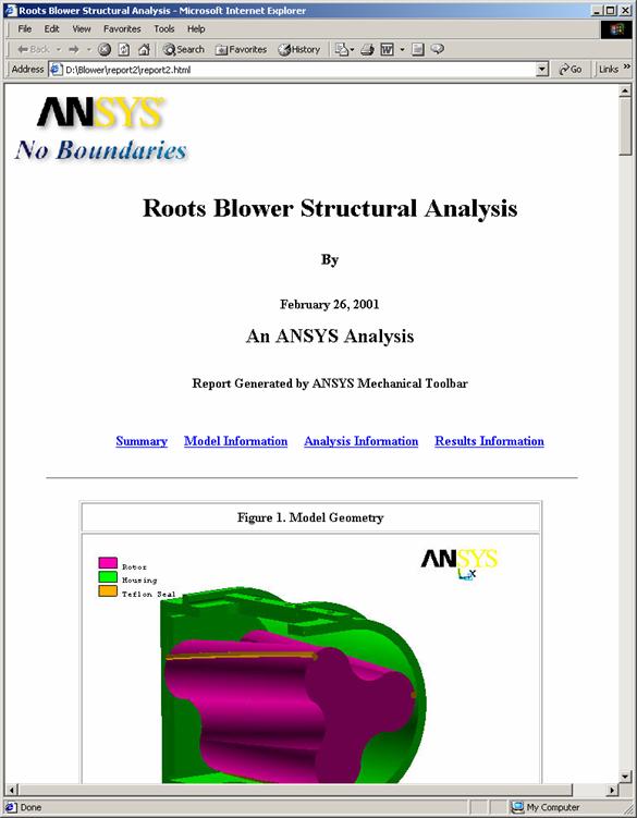
Conclusions:
We have completed our analysis. What have we learned about the roots
blower? The stresses are well below the
yield stress of the materials. The
radial deflection of the rotor is over 0.003 inches. What affect will this have on the performance
of the blower? What can we do to reduce
this deflection and hence minimize the clearances and leakage? What would happen if we made the rotors
hollow? The mass would be reduced, and
hence the centrifugal loading, but the stiffness would also be reduced.
A. We have completed our
analysis. Exit ANSYS by picking: File >Exit.
B. Quit - No save!
C.
14.A08D0C9EA79F9BACE118C8200AA004BA90B02000000080000000E0000005F005200650066003500300037003800320038003100340036000000
13.1.C08D0C9EA79F9BACE118C8200AA004BA90B02000000080000000E0000005F005200650066003400390039003800300036003900390038000000
13.1.C08D0C9EA79F9BACE118C8200AA004BA90B02000000080000000E0000005F005200650066003400390039003800300036003900390038000000
13.1.C08D0C9EA79F9BACE118C8200AA004BA90B02000000080000000E0000005F005200650066003400390039003800300036003900390038000000
|
14.B08D0C9EA79F9BACE118C8200AA004BA90B02000000080000000E0000005F005200650066003500300037003800320038003100350032000000
13.1.C08D0C9EA79F9BACE118C8200AA004BA90B02000000080000000E0000005F005200650066003400390039003800300036003900390038000000
13.1.C08D0C9EA79F9BACE118C8200AA004BA90B02000000080000000E0000005F005200650066003400390039003800300036003900390038000000
13.1.C08D0C9EA79F9BACE118C8200AA004BA90B02000000080000000E0000005F005200650066003400390039003800300036003900390038000000
|
14.C08D0C9EA79F9BACE118C8200AA004BA90B02000000080000000E0000005F005200650066003500300037003800320038003100360030000000
13.1.C08D0C9EA79F9BACE118C8200AA004BA90B02000000080000000E0000005F005200650066003400390039003800300036003900390038000000
13.1.C08D0C9EA79F9BACE118C8200AA004BA90B02000000080000000E0000005F005200650066003400390039003800300036003900390038000000
13.1.C08D0C9EA79F9BACE118C8200AA004BA90B02000000080000000E0000005F005200650066003400390039003800300036003900390038000000
|