25 Watt MosFet Audio Amplifier
High Quality simple unit
No need for a preamplifier
Circuit diagram:
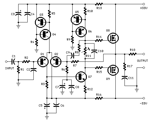
Parts:
R1,R4_________47K 1/4W Resistors
R2____________4K7 1/4W Resistor
R3____________1K5 1/4W Resistor
R5__________390R 1/4W Resistor
R6__________470R 1/4W Resistor
R7___________33K 1/4W Resistor
R8__________150K 1/4W Resistor
R9___________15K 1/4W Resistor
R10__________27R 1/4W Resistor
R11_________500R 1/2W Trimmer Cermet
R12,R13,R16__10R 1/4W Resistors
R14,R15_____220R 1/4W Resistors
R17___________8R2 2W Resistor
R18____________R22 4W Resistor (wirewound)
C1___________470nF 63V Polyester Capacitor
C2___________330pF 63V Polystyrene Capacitor
C3,C5________470µF 63V Electrolytic Capacitors
C4,C6,C8,C11_100nF 63V Polyester Capacitors
C7___________100µF 25V Electrolytic Capacitor
C9____________10pF 63V Polystyrene Capacitor
C10____________1µF 63V Polyester Capacitor
Q1--Q5_____BC560C 45V 100mA Low noise High gain PNP Transistors
Q6_________BD140 80V 1.5A PNP Transistor
Q7_________BD139 80V 1.5A NPN Transistor
Q8_________IRF532 100V 12A N-Channel Hexfet Transistor
Q9_________IRF9532 100V 10A P-Channel Hexfet Transistor
Power supply circuit diagram:
Parts:
R1____________3K3 1/2W Resistor
C1___________10nF 1000V Polyester Capacitor
C2,C3______4700µF 50V Electrolytic Capacitors
C4,C5_______100nF 63V Polyester Capacitors
D1__________200V 8A Diode bridge
D2__________5mm. Red LED
F1,F2_______3.15A Fuses with sockets
T1__________220V Primary, 25 + 25V Secondary 120VA Mains transformer
PL1_________Male Mains plug
SW1_________SPST Mains switch
Notes:
Technical data: Output power: well in excess of 25Watt RMS @ 8
Ohm (1KHz sinewave)
Sensitivity: 200mV input for 25W output
Frequency response: 30Hz to 20KHz -1dB
Total harmonic distortion @ 1KHz: 0.1W 1W 10W 20W 25W Total harmonic
distortion @10KHz: 0.1W 1W 10W 20W 25W
Unconditionally stable on capacitive loads
Having Questions?
|
|
|
|
|