MULTILEVEL INVERTER WITH TWO CONDUCTION BRANCHES
Abstract. This paper describes multilevel tension inverters in witch each alternance of load tension is approximated with several levels, depending on the utilized schema and by driving circuits for electronique devices. The tension level also depends on the used schema and by the capacities connected in parallel with the power supply. Multilevel converters were developed for high tension used in electric ac actions. Following this purpose, several serial converters are presented in Figure 1. In Figure 2, a 2-level inverter, obtained by serial connecting two monophase inverters. It's more convenable to connect several serial devices than several inverters. So, two problems are solved: high level supply tension can be used and the output tension it's synthesize with multilevels.
The step matrix for the inverter in Figure 4 can be presented in Table 2.P01?
Fig. 6. Three level inverter; equivalent circuit for branches 1 and 2 in conduction.
Fig. 7. Multi-level inverters.p03a?
For the inverter in Figure 7, where we have four capacitors connected in parallel on the power supply, the step matrix is different. The matrix depends on the current route from power supply to load.
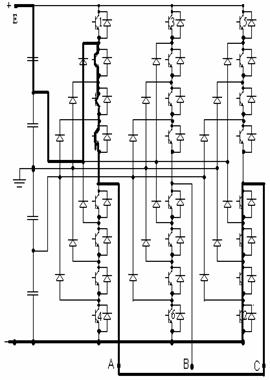
Fig. 8. Multi-level inverter. Equivalent circuit for the branches 1 and 2 in conduction state. P03?
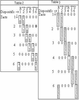
For the inverter presented in figure 8, the step matrix is presents in Table 3.
The step matrix is used to synthesize the driving circuit, considering that a device can be drive several times per period.
In Figure ? is presented the simulation of the two devices in steady state using SPICE.
CONCLUSIONS
The number of levels depends on the number of devices in conduction state on every branch on every clock period. The number of the levels also depends on the conducting branches number because there are inverters with 2 or 3 conducting devices.
This paper presents only the three phase inverters with two branches in conduction, in steady state, and disadvantages for those converters;
Great number of semiconductor devices used;
The use of non-polarized condensers with high capacity;
Figure 1 presents a multi-level inverter in which, in steady state, only three devices must be drive.
For the inverter presented in Figure 5 or Figure 7 and other variants, the tension levels are different from E/2 and we can say that the output tension is synthesized with pulses or we have a pulse inverter.
Multi level inverters with two branches, in witch we have three devices in conduction, uses only three capacitors connected in parallel on power supply.
We obtain a lower cost and lower sizes comparing to the multi level inverter witch uses four parallel-connected capacitors on power supply.
The inverter devices can be bipolar transistors but we can use IGBT transistors or better, IGBT modules.
On every multi level inverter the driving frequency can have a range from lower to high frequencies, depending on the used semiconductor device type.
So, we can drive the speed for the asynchronous machine if we use PWM or super modulation for the inverter devices.
The step matrix is used to synthesize the driving circuit, considering that a device can be drive several times per period.
At the inverter with two branches in conduction in steady-state, the tension on devices at startup is E/2 comparing with the inverter with three devices in conduction in steady-state where the tension on devices at startup is 2E/3.
Keith Corzine, Xiaomin Kuo. James R. Baker., Dynamic Average-Value Modeling of a Four-Level Drive System, IEEE Transaction on POWER ELECTRONICS, March 2003, volume 18, nr 2, pag 619- 627.
C.K. Lee et l.a., A randomizet Voltage Vector Switching Scheme for Three-level Power Inverter., IEEE Transaction on POWER ELECTRONICS, IANUARY 2002, volume 17, nr 1, pag. 94-99.
Subrata K. Mondal., Bimal K. Bose., Valentin Oleschuk Joao O. P., Space Vector Width Moldulation of Three-level inverter Extending Operation Into Overmodulation Region. IEEE Transaction on POWER ELECTRONICS, IANUARY 2003, volume 18, nr 2, pag 604- 611.
M Imecs., .a.a. Power Electronics Bucharest 1983.
Nadira Sabanovic, Asif Sabanovic, and Kouhei Ohniski, SLODIING MODES CONTROL OF THREE
Cerbulescu D., Cerbulescu C., The speed control of asyncronous motors using two inverter, IEE JAPAN IAS'92, 24-25 august 1992, A 6 the annual conference of industrial application societis international session records, Nagoya, E-3-4 pag E57-E59.
Cerbulescu D., Power Static converters, Vol 1,
Cerbulescu D., Power Static converters, Vol 2,
Cerbulescu D., Cerbulescu C. C., THREE-PHASE RECTIFIER WITH POWER FACTOR COTROLLED, Anale of University of Craiova, seria: AUTOMATION, COMPUTERS,
? SIMULATION AND LABORATORY RESULTS
|
