Advanced Application Timing Presentation Overview
This presentation is an in-depth look into the new LabVIEW Timed Loop feature. The context for the material is for real-time application development. As part of the presentation there are 5 demos which are described in this document.
The time for this presentation should be about an hour.
The presentation contains a variety of demos interspersed throughout. The demos are designed to reinforce the strategies presented in the slides and also to maintain interest from the audience. The demos you will need to learn for use in this seminar are listed in the table below along with a short description. The instructor notes and slide placeholders remind you when to give a particular demo. The following table lists the page numbers where you will find the detailed demo script for each demo.
|
Demo Name |
Slide |
Duration |
Description |
Page |
|
Configuring a Timed |
8 |
10 min |
Basics of using a timed loop, doing multirate loops | |
|
Priority and Preemption |
12 |
10 min |
Use the trace tool to visualize timed loops execution | |
|
Synchronizing Loops |
14 |
10 min |
Use timed loop functions to synchronize the start | |
|
Adaptive Rate |
16 |
7 min |
Demonstrates use of dynamic feedback from loop | |
|
Using a DAQmx timing source |
18 |
10 min |
Shows how to use a DAQ timebase for a timed loop |
All of the demos in this seminar require the demo equipment set.
Hardware |
Software |
|
PXI Chassis |
LabVIEW 7.1 |
|
PXI 817x or 8186 RT Controller |
LabVIEW 7.1 Real-Time Module |
|
PXI E-Series DA 13113s188n Q device |
LabVIEW Execution Trace Toolkit |
|
BNC-2120 or DAQ Signal Accessory |
NI-DAQmx 7.2 |
|
68 Pin MIO Cable |
MAX 3.1 |
|
Crossover cable or network hub | |
|
Host computer |
The seminar requires the host computer to be networked with the PXI RT chassis.
The demo script assumes that you are networked via the crossover and therefore you will need to configure your host to use a static IP address.
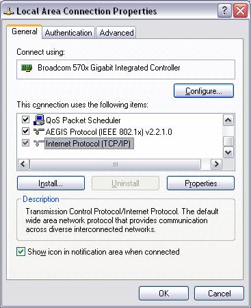
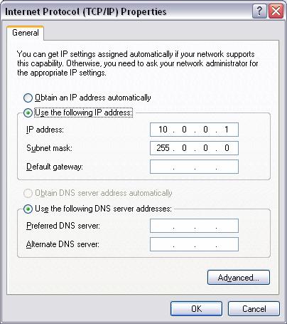
Note: It is recommended that you use an 817x or 8186 series controller for this presentation because the microsecond timing feature of the timed loop is only available in these controllers.
Network the PXI system to the host PC. Follow the directions in the Network Configuration section earlier in this document.
Reset the IP address of the controller. For 8176 controllers, use an IP reset floppy disk created with MAX. For 8186 controllers reset the IP address by changing BIOS settings or using the dip switches inside the controller. Refer to the 8186 manual for more information on resetting the IP address.
https://www.ni.com/pdf/manuals/370747a.pdf -> 8186 Manual
Power up the controller into RT.
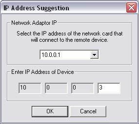
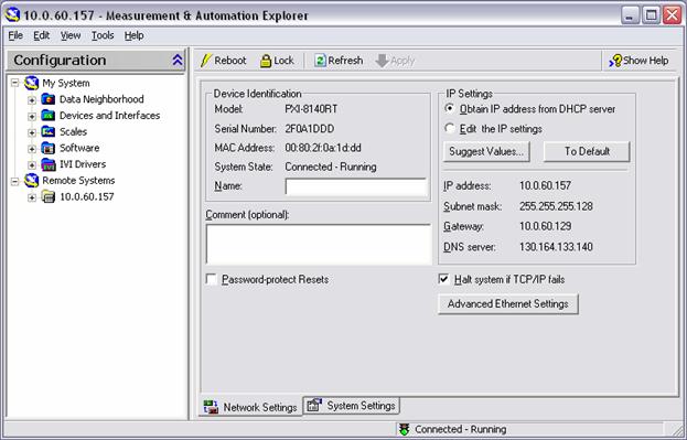
Open MAX and expand Remote Systems. The PXI system will appear with an IP address of 0.0.0.0.
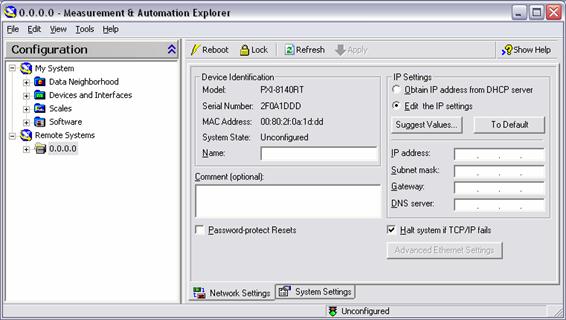
Click on Suggest Values and enter an IP address for the chassis of 10.0.0.3. Click OK. Note that this IP address should not conflict with either the host computer IP address.
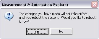
Click on Apply to enable settings. You will be prompted to reboot, click Yes.
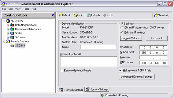
When the controller finishes rebooting it will appear with the configured IP address in MAX.
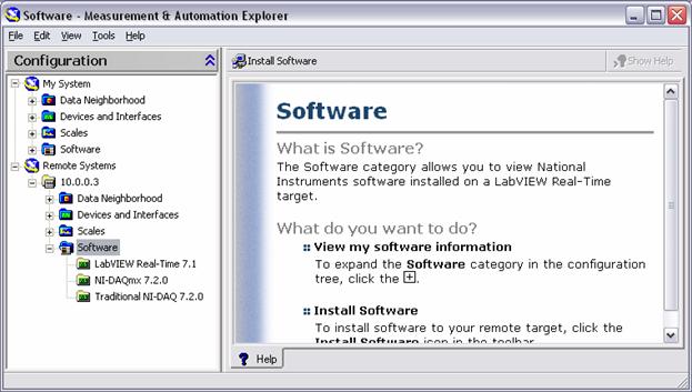
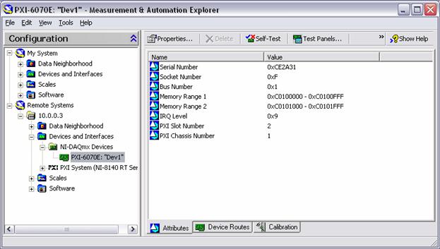
Verify the correct software is installed on the RT controller. Expand 10.0.0.3 >>Software. Other software may be installed, but you must have at minimum the software versions seen in the screenshot. If this software is not installed refer to the Appendix - Software Installation PXI Controller for the software installation procedure.
Under Remote Systems expand 10.0.0.3>> Devices and Interfaces>> NI-DAQmx Devices. The PXI DAQ device should appear. Verify it has the correct device name: Dev1. If the device name is incorrect, press F2 on the keyboard to edit the device name.
Connect the 68 pin cable from the PXI DAQ card to the DAQ Signal Accessory or the BNC-2120.
To verify the setup, go through any the demos.
Demo 1 - Configuring a Timed
Demonstrate how to configure a timed loop in LabVIEW. Show multiple timed loops, including one with microsecond timing .
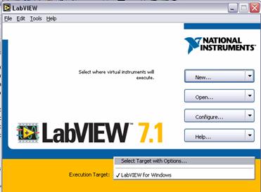
Open LabVIEW. Do not target the RT target yet.
Create a new VI, switch to the block diagram.
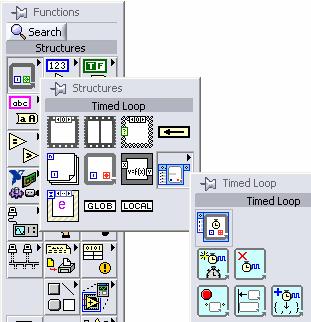
Place a Timed

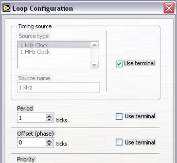
Double-click on the timed loop configuration node.

Explain the different options for configuring the timed loop.
Timing Source -the timebase for the loop
period. Note: the 1MHz clock is only
available for supported RT Targets (8170 series and above, CVS, and Desktop
PCs running RT with P3/ P4 processor.) Period - how many ticks from the timing source will
elapse between each loop iteration Offset - a configurable delay before the first
iteration begins Priority - the relative priority of a loop compared to
other loops Loop name - Identifier for using other timed loop
functions Timed loop action. - this determines
how the loop will behave when it Timeout - Can force loop to iterate when timeout
expires Use Terminal - allows configuration of
parameter to be done programmatically in
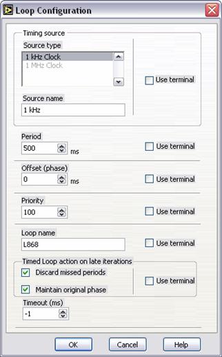
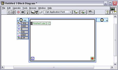
Select the 1kHz time source, and configure the loop for a period of 500ms. Click OK.
Finish the VI by creating an indicator on the iteration terminal of the loop and a stop button.
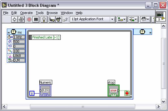
Save the VI as Demo1.vi.
Switch to the front panel and run the VI. The iteration terminal will update every half second.
Stop the VI.
Close the VI and switch execution target to the RT PXI chassis.
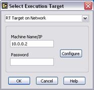
a. From the Execution target pull-down menu choose Select Target with Options
b. Select RT Target on Network from the pull down menu. Type in the PXI IP address for the Machine Name/IP in the Select Execution Target dialog and click OK.
Open the Demo1 VI that you created in the previous part of the demo.
Switch back to the block diagram. Create another timed loop. Double-click on the configuration node of the second timed loop.
Select the 1 MHz timing source and make the period 500 us. Click OK to exit the configuration dialog.
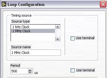
Note: The 1 MHz timing source is supported by only certain RT targets, it is not supported by Windows. 8140 series controllers and FieldPoint targets do not support the 1MHz timing source.
Note 2: You cannot run a loop with 1 microsecond as the period. The timed loop itself has an overhead of several microseconds.
Create
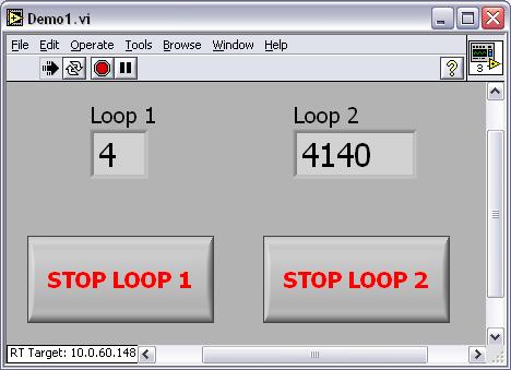
an indicator for its iteration terminal and a stop button. Rename the indicators for the iteration
terminals to be Loop 1 and
Return to the front panel and edit the size of the indicators so that they can be seen.
Run the VI. You will be prompted to save the VI. Save the VI and it will download and begin executing on the RT PXI chassis.
The fast iteration terminal will update at a rate of 2 kHz, while the previously created iteration terminal will update at its original rate of 2Hz.
End Demo 1
Demo 2 - Priority and Preemption of Real-Time Tasks
Use the LabVIEW Execution Trace Toolkit to demonstrate how priority configuration affects the execution of timed loops.
Launch LabVIEW. Switch execution target to the RT PXI chassis.
Open the Preemption demo VI located in Preemption demo.llb.
Switch to the block diagram.
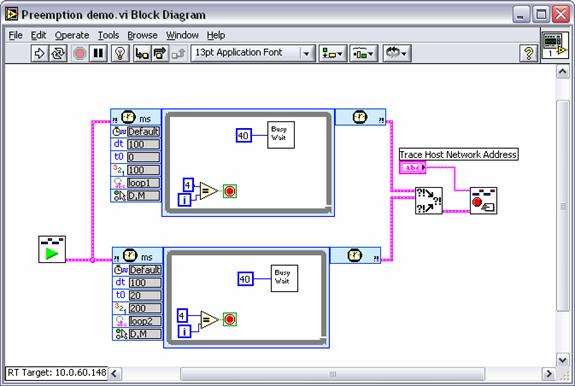
Open the configuration dialog for each loop and point out the following things.
a. The period for each loop is 100 ms.
b. The priority for the top loop is 100
c. The priority for the bottom loop is 200 and it has an offset of 20 ms.
d. The code within both loops is just a busy wait that forces the iteration to take 40 ms to complete
Point out the Execution Trace Toolkit VIs that will be used to log the execution of the demo.
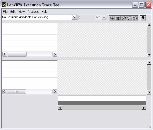
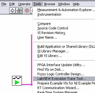
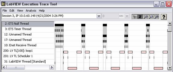
Open the LabVIEW Execution Trace Tool.
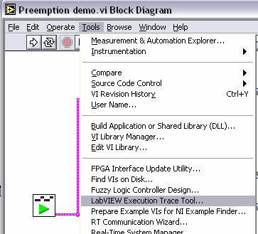
The LabVIEW Execution Trace Toolkit will show the execution of the demo VI so that we can visualize the preemption of the timed loops.
A timeline will be shown here This will show VI execution This pane will show thread execution
Go to the front panel of the Preemption demo VI. Type in the IP address of the host computer. This will tell the VI where to send the trace session when it is finished executing.
Run the VI, it will execute quickly and then send the trace session to the Execution Trace Tool. Note: if you do not have the Execution Trace Tool open, the VI will not send the trace session.
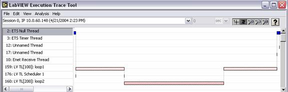
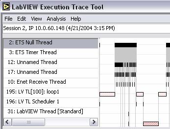
When the VI is finished executing, bring up the Execution Trace Tool. It will display the execution trace session. You may need to resize the window to display the relevant data.
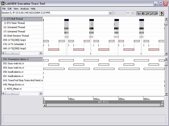
The top view shows the thread execution. Point out that there is a thread for each of the loops, with the loop name and the priority. At the bottom of the trace tool there is a time scale.
![]()

The bars represent the execution of the thread where the loop code is executing.
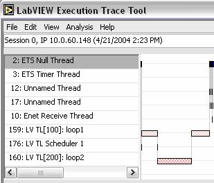
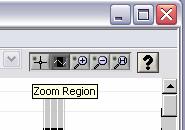
Use the zoom tool to get a better view of the execution.
![]()
Zoom in on an iteration of both loops. Recall that the loop periods where 100ms for both loops.
zoom
section
![]()
![]()
![]()
![]()
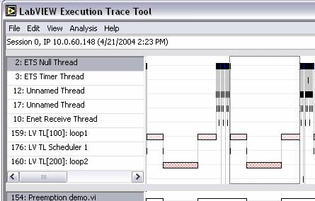
Point out how loop1 began executing, and loop2 started after an offset of 20 ms, as it was configured. However, since loop2 had a higher priority, it preempted loop1. When loop2 was finished, the execution returned to loop1 to finish the iteration.
loop2 preempts loop1![]()
As expected, the total execution time for the code in loop1 and loop2 is 40 ms.
Optional
If you have time, return to the block diagram of the VI and swap the priority levels of the loop. Make the loop1 priority higher than that of loop2.
Run the VI and see how the trace session differs from the original one. Note that you will need to switch views to the latest session created using the pull-down menu of the Execution Trace Tool.

Zoom in on an iteration of both loops.
Notice that loop1 completes it's iteration before loop2 begins. Also notice that there is a thread swap 20 ms after loop1 begins. Recall that loop2 had a 20 ms offset. When the offset elapsed, the Timed Loop Scheduler tried to start loop2, however it was preempted by loop1. If you removed the offset from loop2, this phenomenon would go away.
End of Demo 2
Demo 3 - Synchronizing Real-Time Tasks
Demonstrate how to synchronize the start of two loops.
Open the Synchronization demo.vi located in Synchronization demo.llb.
Switch to the block diagram. This is the same VI that was used for the preemption demo only there is a dummy configuration VI executing before one of the loops.
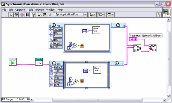
The configuration VI causes a delay in when the second loop starts. We will again use the Execution Trace Toolkit to demonstrate the effect of the delay.
Open the Execution Trace Tool if it's not already open.
Go to the front panel of the Synchronization demo VI and enter the host IP address.
Run the VI.
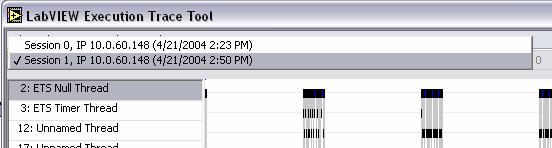
Switch to the Execution Trace Tool and select the latest session created from the pull down menu.

Notice that loop1 executed a complete iteration before loop2 ever began executed.

Go back to the block diagram of the Synchronization demo VI, we will add code to synchronize the loop start.
Note: If you do not have much time, you can optionally opened the Synchronization demo finished VI which is located in the same VI library. This VI has the code already built for synchronizing.
Add the Synchronized Timed

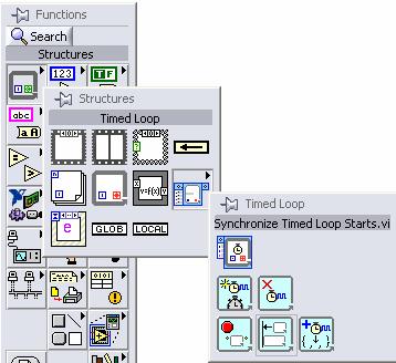
Complete the block diagram as shown below. You will have to create a constant for the loop names and the synchronization group name inputs. The loop names must match the actual loop names of loop1 and loop2.
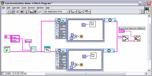
Make sure that the host IP address in the front panel is correct and run the VI.
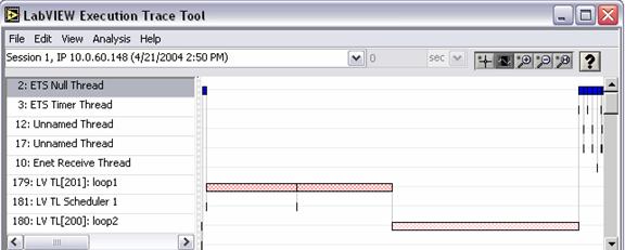
Go back to the Execution Trace Tool and display the latest trace session.
Notice how this time the loop starts were synchronized. Loop2 starts 20ms after loop1 because of the configured offset.
End Demo 3
Demo 4 - Adaptive Rate Program
Demonstrate the dynamic feedback from a timed loop to find the fastest rate that a program can while still keeping real-time.
Launch LabVIEW and switch execution target to the RT PXI chassis.
Open the Adaptive rate demo VI located in the Adaptive rate demo.llb.
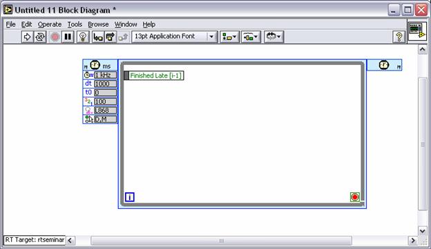
Switch to the block diagram to show the code.

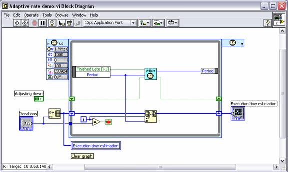
Note that the loop is configured to use the 1MHz timebase and the initial period is 1000 us, or 1 ms.
Point out that we are using the dynamic feedback from the loop to adjust the rate. The two pieces of feedback that we are using are whether we finished late and what the previous period was. The execution time graph will show how long each iteration took.
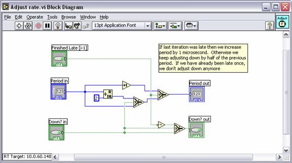
Optional - Open the Adjust rate VI and show the block diagram. If the last iteration finished on time, the period is cut in half. If last iteration was late then we increase period by 1 microsecond. If we have already been late once, we do not adjust down anymore. Close the Adjust rate VI when you are finished explaining.
Return to the front panel of the Adaptive rate demo VI.
Run the VI.
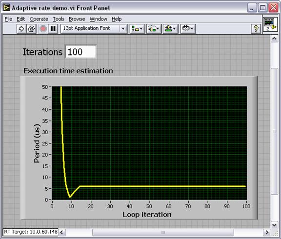
The graph will show the execution time for each iteration of the timed loop. The time decreases rapidly until the loop finished late. Then it added 1 microsecond to the period until it finished on time.
We will add a piece of code to benchmark at what period it can execute without causing the loop to be late.
Return to the block diagram and place the loop code VI found in Adaptive rate demo.llb. This VI represents the code that we are wishing to benchmark.
Return to the front panel and run the VI.
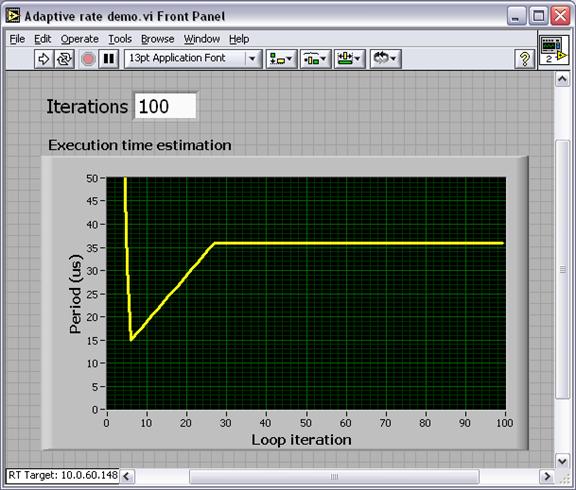
This code can be run at about 36 microsecond loop rates without being late.
End of Demo 4
Demo 5 - Using a DAQmx Timing Source
Demonstrate the dynamic feedback from a timed loop to find the fastest rate that a program can while still keeping real-time.
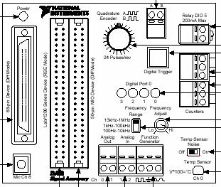
If
using a DAQ Signal Accessory, connect the A or B output from the encoder to
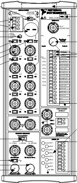
Counter 0 Source If
using the BNC-2120, connect the Clock output from the encoder to PFI 8
input, which is the source input for counter 0.
![]()
![]()
![]()
![]()
![]()
![]()
![]()
Open LabVIEW and switch execution to target to the RT PXI system.
Open a new VI and switch to the block diagram. Place a timed loop from the Timed Loop palette in the Structures palette.


Double click the configuration node of the timed loop to configure it.

Explain how you can set different aspects of the timed loop in this configuration window, including time source, offset, phase, priority, etc. Select Use Terminal for the Timing source.

Place the DAQmx Create Timing Source VI to the left of the timed loop.

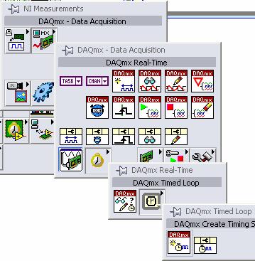
Create constants for the counter input and the source input. Select Devx/ctr1 for the counter and Devx/PFI8 for the source. Where Devx is your E-series DAQ device that is connected to the signal accessory. Wire the timing source out to the source input of the timed loop. The encoder on the signal accessory should be connected to Counter 0. Here we specify that we want the loop to wake up each time the encoder produces a pulse.
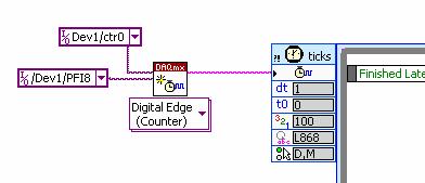
Finish the diagram by creating an indicator on the iteration terminal and add a stop button.
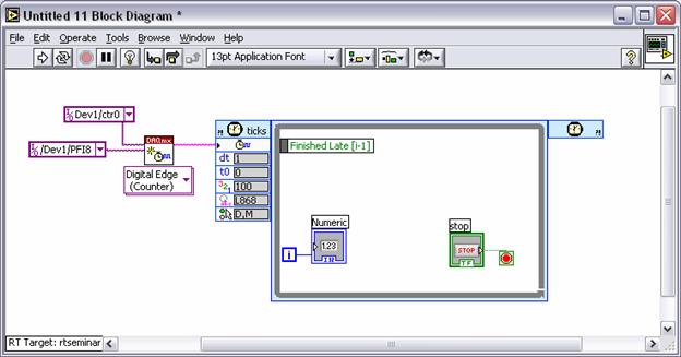
Switch to the block diagram and run the VI. You will be prompted to save it. Save it as Demo9.vi.
Turn the encoder knob on the signal accessory. This will generate pulses off the encoder and wake up the timed loop, incrementing the iteration terminal. Note that each tick of the BNC -2120 encoder produces 4 pulses.
"I have been able to time the execution of this loop with hardware events from the data acquisition board."
Appendix
The host computer needs to have the following software installed.
LabVIEW 7.1
LabVIEW 7.1 Real-Time Module
NI-DAQmx 7.2 with RT support
These installation instructions refer to the network software installation. These can also be installed from the appropriate CDs.
Install LabVIEW 7.1 PDS with the default selections. The installer can be found at \\nirvana\NIInstallers\Current\ni\LabVIEW\7.1 - Windows - English\LV_71_PDS\setup.exe
When the installer is finished, it will prompt you to begin the Driver CD installation. Do NOT install the drivers yet, cancel it.
Install the LabVIEW 7.1 Real-Time Module for ETS Targets. The installer can be found at \\nirvana\NIInstallers\Current\NI\LabVIEW Real-Time\Windows\7.1\English\ETS\setup.exe
When the LabVIEW Real-Time installation has completed, it will prompt you to start the Driver CD installation. You will have to point the installer to the network location at \\nirvana\NIInstallers\Current\NI\DriverCD\2004.05\DCD-May04-1
You can install all the drivers you need. The drivers needed for this seminar are NI-DAQmx 7.2 and FieldPoint 4.1. Verify that these two drivers are installed with support for LabVIEW Real-Time. See the screen shots below.
Make sure these are installed for the
demos

![]()

Once you have installed these drivers, you have finished installing software on the host computer.
Note that the method for installing software on remote systems has changed with MAX 3.1.
Network your PXI system with your host computer as described in the Configuring the Demo Equipment section of this document.
Open MAX and expand Remote Systems.
You should see the PXI system with the IP address you configured it with. Expand PXI_IP_Address>>Software.
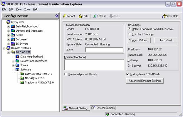
If the list appears as above with the correct software versions, the PXI system has the software necessary and there is no need to install software. If you are missing some or all of the components proceed to step 5. Note: You may have other software installed as well, this is the minimum software needed for the demos.
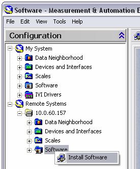
If you need to install software, right-click on Software and select Install Software.

In the LabVIEW Real-Time Install Software Wizard select LabVIEW Real-Time 7.1, Traditional NI-DAQ, and NI-DAQmx 7.2.0 for installation. Note: If you are installing this software for the first time on an 8140-series controller you should install LabVIEW Real-Time 7.1 first, reboot the controller then install the DAQ drivers. This is a documented known issue.
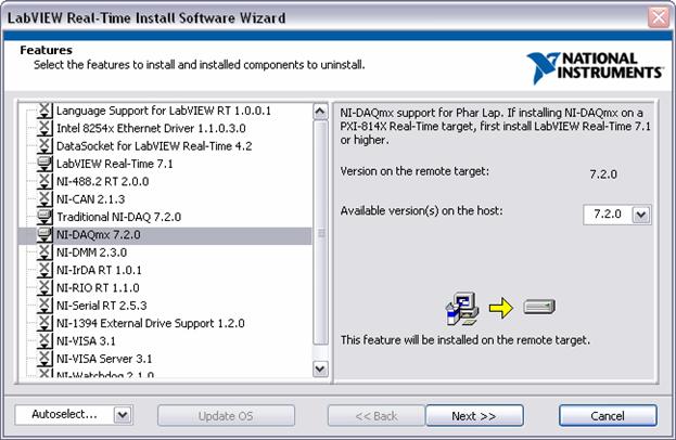
Note: You may choose other software for installation if so desired.
Click next twice to complete the installation. When it is finished, the PXI unit should be ready for use.
LabVIEW Real-Time Module 7.1 Readme
This document is an extension of the LabVIEW Real-Time Module 7.1 Release Notes. This readme briefly describes some known issues. Refer to ni.com/support for the latest known issues.
Table of Contents for Known Issues
NI
PXI-8156B Controllers Cannot Execute LabVIEW Timed
Error 15550 When Installing Software to an NI PXI-8145RT Controller.
Custom Probes Do Not Function Properly on RT Target.
The
RT Communication Wizard Converts Normal Priority Timed Loop
Cannot Communicate with NI PCI-7041 Plug-In Device Using MAX on Multiprocessor or Hyperthreading Computers.
LabVIEW Real-Time Module Does Not Support the LabWindows/CVI 7.0 TCP/IP Library.
NI
PXI-8156B Controllers Cannot Execute LabVIEW Timed
The lvalarms.dll installed to the ni-rt/system directory on the 8156B does not support the Timed Loop. You can transfer the lvalarms.dll from the National Instruments\RT Images\LabVIEW\7.1\E001 directory on the host computer to the ni-rt/system directory on the RT target with an FTP client.
Error 15550 When Installing Software to an NI PXI-8145RT Controller
When installing LabVIEW Real-Time 7.1 and NI-DAQmx software to an NI PXI-8145RT controller, MAX returns the following message:
The operation could not be completed. Operation failed with error code: 15550. Possible reasons(s): The password you typed in was incorrect.
You must install the LabVIEW Real-Time 7.1 software to the RT target and then reboot the controller. You then can install all other necessary software to the RT target. Also, you cannot install NI-DAQmx if the NI PXI-8145RT controller is in Safe Mode.
Custom Probes Do Not Function Properly on RT Target
Custom probes do not function properly when you use the custom probe in a VI running on the RT target. You must mass compile your custom probes directory to update the probe for proper operation.
The
RT Communication Wizard Converts Normal Priority Timed Loop
National
Instruments recommends that you execute
Cannot Communicate with NI PCI-7041 Plug-In Device Using MAX On Multiprocessor or Hyperthreading Computers
After installation, MAX displays the NI PCI-7041 plug-in device under the Devices and Interfaces category. However, MAX cannot communicate with the remote device to show the software installed on the device. Also, MAX returns an error when you attempt to reboot the device. If you are using a multiprocessor system, you must disable the additional processor (including Hyperthreading). Refer to the National Instruments Web site at ni.com/info and enter the info code rtmulti for information about communicating with an NI PCI-7041 plug-in device using MAX.
LabVIEW Real-Time Module Does Not Support the LabWindows/CVI 7.0 TCP/IP Library
The LabVIEW Real-Time Module 7.1 does not support the LabWindows/CVI 7.0 TCP/IP library on RT targets. Programs built with LabWindows/CVI 7.0 that use the LabWindows/CVI TCP/IP library will not work with LabVIEW Real-Time Module 7.1. National Instruments will provide an updated LabWindows/CVI 7.1 in the future that is fully compatible with the LabVIEW Real-Time Module 7.1.
|
