ALTE DOCUMENTE
|
|||||
EUROPEAN STANDARD prEN 1998-1
NORME EUROPÉENNE
EUROPÄISCHE NORM
|
|
Doc CEN/TC250/SC8/N269
English version
Eurocode 8: Design of structures for earthquake resistance
Part 1: General rules, seismic actions and rules for buildings
DRAFT No 1
May 2000
CEN
European Committee for Standardization
Comité Européen de Normalisation
Europäisches Komitee für Normung
Central Secretariat: rue de Stassart 36, B1050 Brussels
|
|
CEN 2000 Copyright reserved to all CEN members
Ref.No prEN 1998-1:2000
FOREWORD
This European Standard has been prepared on behalf of Technical Committee CEN/TC250 "Structural Eurocodes" by CEN/TC250/SC8 "Eurocode 8: Earthquake resistance design of structures", the Secretariat of which is held by LNEC on behalf of IPQ. CEN/TC250, the Secretariat of which is held by BSI, is responsible for all Structural Eurocodes.
The text of the draft standard was submitted to the formal vote and was approved by CEN as EN 1998-1 on YYYY-MM-DD.
No existing European Standard is superseded.
This European Standard has been prepared under a mandate given to CEN by the European Commission and the European Free Trade Association.
The European Commission initiated the preparation of a set of technical rules for the structural design of building and civil engineering works which would serve initially as an alternative to different rules in force in the Member States and would ultimately replace them. These became known as STRUCTURAL EUROCODES. Subsequently the European Commission gave mandates to CEN for the development of the Structural Eurocodes, initially as European Prestandards (ENV) and later as European Standards (EN). The European Free Trade Association gave similar mandates to CEN.
Structural Eurocodes relate to Council Directive 89/106/EEC on construction products and Council Directive 71/305/EEC and 89/440/EEC on public works and equivalent EFTA Directives.
The Structural Eurocodes programme comprises the following standards generally consisting of a number of parts:
EN 1990 Basis of design for structural Eurocodes
EN 1991 Eurocode 1: Actions on structures
EN 1992 Eurocode 2: Design of concrete structures
EN 1993 Eurocode 3: Design of steel structures
EN 1994 Eurocode 4: Design of composite steel and concrete structures
EN 1995 Eurocode 5: Design of timber structures
EN 1996 Eurocode 6: Design of masonry structures
EN 1997 Eurocode 7 Geotechnical design
EN 1998 Eurocode 8: Design of structures for earthquake resistance
EN 1999 Eurocode 9: Design of aluminium structures
EN 1998-1 Eurocode 8: Design of structures for earthquake resistance - - Part 1: General rules, seismic actions and rules for buildings
EN 1998-2 Eurocode 8: Design of structures for earthquake resistance - Part 2: Bridges
EN 1998-3 Eurocode 8: Design of structures for earthquake resistance - Part 3: Strengthening and repair of buildings
EN 1998-4 Eurocode 8: Design of structures for earthquake resistance - Part 4: Silos, tanks and pipelines
EN 1998-5 Eurocode 8: Design of structures for earthquake resistance - Part 5: Foundations, retaining structures and geotechnical aspects
EN 1998-6 Eurocode 8: Design of structures for earthquake resistance- Part 6: Towers, masts and chimneys
The Member States of the EU and EFTA recognise that EUROCODES serve as reference documents for the following purposes:
as a means to prove compliance of building and civil engineering works with the essential requirements of Council Directive 89/106/EEC, particularly Essential Requirement No.1 - Mechanical resistance and stability
as a basis for specifying contracts for the execution of construction works and related engineering services
as a framework for drawing up harmonized technical specifications for construction products
The Eurocode standards provide common structural design rules for everyday use for the design of whole structures and component products of both traditional and innovative nature. They embrace the structural design of most of works and products in the construction field. Exotic, novel or extremely unusual forms of construction or design conditions are not specifically covered and additional expert consideration will be required by the designer.
Eurocode standards recognise the responsibility of regulatory authorities in each Member State and has safeguarded their right to determine values related to regulatory safety matters at national level where these continue to vary from State to State. These are dealt with in the main normative text of this Eurocode Part by use of a range of values, classes or symbols with accompanying footnotes.
The Eurocode Standard shall be given the status of a national standard, either by publication of an identical text or by endorsement, at latest by YYYY-MM-DD. Conflicting national standards shall be withdrawn at the latest by YYYY-MM-DD. The national implementation standard may include a national title page, national foreword (informative) and an informative national annex as necessary.
Note: The following texts, coming from ENV 1998-1-1, ENV 1998-1-2 and ENV 1998-1-3, are kept for the time being. They shall be later re-evaluated in view of the final draft of prEN 1998-1.
Matters specific to this Prestandard (Part 1-1)
(16) The scope of Eurocode 8 is defined in clause 1.1.1 and the scope of this Part of Eurocode 8 is defined in clause 1.1.2. Additional Parts of Eurocode 8 which are planned are indicated in clause 1.1.3.
(17) This Prestandard was developed from one of the Parts that was included in the Draft of Eurocode 8 dated May 1988 published by the CEC and subjected to public enquiry. Such Draft contained also Parts 1-2 and 1-3 which are now presented as separate Prestandards.
(18) As mentioned in clause 1.1.1, attention must be paid to the fact that for the design of structures in seismic regions the provisions of Eurocode 8 are to be applied in addition to the provisions of the other relevant Eurocodes.
(19) In using this Prestandard in practice, particular regard should be paid to the underlying assumptions given in clause 1.3.
(20) One fundamental issue in this Prestandard is the definition of the seismic action. Given the wide difference of seismic hazard and seismo-genetic characteristics in the various member countries, the seismic action is herein defined by a sufficiently large number of parameters whose numerical values are within so that the authorities in each member country may adjust the seismic action to their specific conditions. It is however considered that, by the use of a common basic model for the representation of the seismic action, an important step is taken in this Prestandard in terms of Code harmonisation.
Matters specific to this Prestandard (Part 1-2)
(16) The scope of Eurocode 8 is defined in ENV 1998-1-1 clause 1.1.1; the scope of this Part of Eurocode 8 is defined in clause 1.1.1 Additional Parts of Eurocode 8 which are planned are indicated in ENV 1998-1-1 clause 1.1.3.
(17) This Prestandard was developed from one of the Parts that was included in the Draft of Eurocode 8 dated May 1988 published by the CEC and subjected to public enquiry. Such Draft contained also Parts 1-2 and 1-3 which are now presented as separate Prestandards.
(18) As mentioned in clause 1.1.1, attention must be paid to the fact that for the design of structures in seismic regions the provisions of Eurocode 8 are to be applied in addition to the provisions other relevant Eurocodes.
(19) In using this Prestandard in practice, particular regard should be paid to the underlying assumptions given in clause 1.3 of Part 1-1.
(20) This Prestandard includes three Appendices which develop some aspects of clauses presented in the main part of the text. They are useful for the conceptual design of buildings and for the analysis of specific cases which allow some simplifications.
Matters specific to this Prestandard (Part 1-3)
(16) The scope of Eurocode 8 is defined in ENV 1998-1-1 clause 1.1.1; and the scope of this Part of Eurocode 8 is defined in clause 1.1. Additional Parts of Eurocode 8 which are planned are indicated in ENV 1998-1-1 clause 1.1.3.
(17) This Prestandard was developed from one of the Parts that was included in the Draft of Eurocode 8 dated May 1988 published by the CEC and subjected to public enquiry. Such Draft contained also Parts 1-1 and 1-2 which are now presented as separate Prestandards.
(18) As mentioned in clause 1.1, attention must be paid to the fact that for the design of structures in seismic regions the provisions of Eurocode 8 are to be applied in addition to the provisions of the other relevant Eurocodes.
(19) In using this Prestandard in practice, particular regard should be paid to the underlying assumptions given in clause 1.3 of Part 1-1.
(20) Although an effort has been made to harmonise the various sections of this Prestandard regarding the various materials, it must be pointed out that differences still exist with respect to the quantity of the contents and to the extent of the details presented. This is the consequence of the fact that in the more seismically active regions of Europe use has been made until now almost exclusively of specific structural materials, and not of others, so that the experience available on these latters from all points of view (including behaviour, modelling, design rules and actual performance during earthquakes) is comparatively limited.
(21) As allowed in Part, 1-1 of Eurocode 8 this Prestandard contains in its chapter related to masonry buildings specific provisions which simplify the design of "simple masonry buildings". These rules are mostly presented with the use of numerical values within [ ] so that the authorities in the member countries may adjust them to their specific conditions.
(22) This Prestandard includes four annexes of informative character related to
- flowcharts for the application of section 2,
- seismic design of precast concrete buildings,
- preliminary dimensioning of boundary elements of rc-walls,
specific rules for steel-concrete composite buildings.
Editorial Note
This document results from the merger of ENV 1998-1-1; 1998-1-2 and 1998-1-3.
Sections 1 to 3 result essentially from ENV 1998-1-1 and changes are indicated with double underlining for new text and strikethrough out for text to be deleted. In some cases a number in refers to the existence of a justification note for the proposed change.
Section 4 results essentially from ENV 1998-1-2 and the changes are also indicated.
Sections 5 and 6 result essentially from sections 2 and 3 of ENV 1998-1-3 but the amount of changes does not allow, in practical terms, to indicate them. Thus the text was totally re-written.
Section 7 is totally new and is intended to replace completely the former Annex D of ENV 1998-1-3.
Section 8 results from section 4 of ENV 1998-1-3 and the changes are indicated.
Section 9, due to unforeseen difficulties within the Project Team, is mostly kept unchanged with regard to section 5 of ENV 1998-1-3.
Section 10 is intended to be a new section of ENV 1998-1 that shall incorporate the general aspects of base isolation already dealt with in ENV 1998-2 and the specific aspects for the design of buildings with such systems. For the moment the section is still void.
(1)P Eurocode 8 applies to the design and construction of buildings and civil engineering works in seismic regions. Its purpose is to ensure, that in the event of earthquakes
damage is limited,
structures important for civil protection remain operational.
NOTE: The random nature of the seismic events and the limited resources available to counter their effects are such as to make the attainment of these goals only partially possible and only measurable in probabilistic terms.
The extent of the probabilistic protection that can be provided to different categories of buildings is a matter of optimal allocation of resources and is therefore expected to vary from country to country, depending on the relative importance of the seismic risk with respect to risks of other origin and on the global economic resources.
To provide the necessary flexibility in this respect, Eurocode 8 contains a set of safety elements whose values are left to the National Authorities to decide so that they can adjust the level of protection to their respective optimal value.
(2) P Special structures with increased risks for the population, such as nuclear power plants and large dams, are beyond the scope of Eurocode 8.
(3) P Eurocode 8 contains only those provisions that, in addition to the provisions of the other relevant Eurocodes, must be observed for the design of structures in seismic regions. It complements in this respect the other Eurocodes.
Eurocode 8 is subdivided into various separate Parts, see 1.1.2 and 1.1.3.
Part 1-1 contains the basic requirements and compliance criteria applicable to buildings and civil engineering works in seismic regions .
In addition, Part 1-1 gives the rules for the representation of seismic actions and for their combination with other actions. Certain types of structures, dealt with in Parts 2 - 5, need complementing rules which are given in these Parts.
(1) P Further Parts of Eurocode 8 include - in addition to Part 1-1 - the following:
- Part 1-2 contains general design rules relevant specifically to buildings,
- Part 1-3 contains specific rules for various structural materials and elements, relevant specifically to buildings,
- Part 1-4 contains provisions for the seismic strengthening and repair of existing buildings,
- Part 2 contains specific provisions relevant to bridges,
- Part 3 contains specific provisions relevant to towers, masts and chimneys,
-Part 4 contains specific provisions relevant to tanks, silos and pipelines,
- Part 5 contains specific provisions relevant to foundations, retaining structures and geotechnical aspects.
(1) P Depending on the character of the individual clauses, distinction is made in this Eurocode between Principles and Application Rules.
(2) P The Principles comprise:
- general statements and definitions for which there is no alternative,
- requirements and analytical models for which no alternative is permitted unless specifically stated.
(3) P The Application Rules are generally recognised rules which follow the Principles and satisfy their requirements.
The Principles are identified by the letter P, following the paragraph number. The other items (without P) are Application Rules, e.g. as this paragraph.
It is permissible to use alternative design rules which differ from the Application Rules given in Eurocode 8, provided that it is shown that the alternative rules accord with the relevant Principles and are at least equivalent with regard to the safety and serviceability achieved for the structures designed according to the Application Rules of Eurocode 8.
P The following assumptions apply:
- structures are designed by appropriately qualified and experienced personnel,
- adequate supervision and quality systems are provided during execution of the work, i.e in design offices, factories, plants and on site,
- construction is carried out by personnel having the appropriate skill and experience,
- the construction materials and products are used as specified in the Eurocodes or in the relevant material or product specifications.
- the structure will be adequately maintained,
- the structure will be used in accordance with the design brief.
In this Eurocode numerical values identified by are given as indications. Different values may be specified by the National Authorities.
(3) P No change of the structure is allowed during the construction phase or during the subsequent life of the structure, unless proper justification and verification is provided. Due to the specific nature of the seismic response this applies even in the case of changes that lead to an increase of the structural resistance.
Unless otherwise stated in the following, the terminology used in International Standard ISO 8930 applies.
The following terms are used in common for all Eurocodes with the following meanings:
- Construction works: Everything that is concerned with or results from construction operations. This term covers both building and civil engineering works. It refers to the complete construction comprising both structural and non-structural elements as well as the geotechnical aspects involved.
- Type of building or civil engineering works: Type of construction works designating its intended purpose, e.g. dwelling house, retaining wall, industrial building, road bridge.
- Type of construction: Indication of principal structural material, e.g. reinforced concrete construction, steel construction, composite construction, timber construction, masonry construction.
- Method of construction: Manner in which the execution will be carried out, e.g. cast in place, prefabricated, cantilevered.
- Construction material: A material used in construction work, e.g. concrete, steel, timber, masonry.
- Structure: Organised combination of connected parts designed to provide adequate rigidity.
- Form of structure: structural type designating the arrangement of structural elements, such as beam, column, arch, foundation piles. Forms of structure are e.g. frames or suspension bridges.
- Structural system: The load bearing elements of a building or civil engineering works and the way in which these elements function together.
- Structural model: The idealisation of the structural system used for the purposes of analysis and design.
- Execution: The activity of creating a building or civil engineering works. The term covers work on site; it may also signify the fabrication of components off site and their subsequent erection on site.
The following terms are used in Part 1-1 with the following meanings:
- Behaviour factor: Factor used for design purposes to reduce the forces obtained from a linear analysis, in order to account for the non-linear response of a structure, associated with the material, the structural system and the design procedures.
- Capacity design method: Design method in which elements of the structural system are chosen and suitably designed and detailed for energy dissipation under severe deformations while all other structural elements are provided with sufficient strength so that the chosen means of energy dissipation can be maintained.
- Critical regions: See dissipative zones.
- Dissipative structure: Structure, which is able to dissipate energy by means of ductile hysteretic behaviour.
- Dissipative zones: Predetermined parts of a dissipative structure where the dissipative capabilities are mainly located (also called critical regions).
- Dynamically independent unit: Structure or part of a structure which is subjected directly to the ground motion and whose response is not affected by the response of adjacent units or structures;
- Importance factor: Factor which relates
to the consequences of a structural failure. used to
express the importance of a building or a civil engineering works.
- Non-dissipative structure: Structure designed for the seismic load case without taking into account the non-linear material behaviour.
- Non-structural elements: Architectural, mechanical or electrical element, system and component which, whether due to lack of strength or to the way it is connected to the structure, is not considered in the seismic design as load carrying element.
(1)P S.I.Units shall be used in accordance with ISO 1000.
For calculations, the following units are recommended:
- forces and loads: kN kN/m, kN/m2
- unit mass: kg/m3
mass: kg
- unit weight: kN/m3
- stresses and strengths: N/mm2 (= MN/m2 or MPa)
- moments (bending, etc): kNm
- acceleration: m/s2
- ground acceleration: g (=9.81 m/s2)
For the material-dependent symbols as well as for symbols not specifically related to earthquakes the provisions of the relevant Eurocodes apply.
Further symbols, used in connection with seismic actions, are defined in the text where they occur, for ease of use. However, in addition, the most frequently occurring symbols used in Part 1-1 are listed and defined in 1.6.2.
AEd design value of the seismic action for the reference return period;
Ed design value of action effects;
Q variable action:
Se(T) ordinate of the elastic horizontal ground acceleration response spectrum (also called "elastic response spectrum") for the reference return period;
Sve(T) ordinate of the elastic ground acceleration spectrum for the vertical component of the seismic action for the reference return period;
DSe(T) ordinate of the elastic displacement response spectrum for the reference return period;
Sd(T) ordinate of the design spectrum for the reference return period;
S soil parameter;
T vibration period of a linear single degree of freedom system;
ag peak ground acceleration (also called "design ground acceleration'') in rock or firm soil for the reference return period;
effective peak ground acceleration (also called
"design ground acceleration'') in rock or firm soil for the reference return
period;
av peak ground acceleration in the vertical direction for the reference return period;
dg peak ground displacement ;
g acceleration of gravity:
q behaviour factor;
a ratio of the design ground acceleration to the acceleration of gravity;
gI importance factor;
y2i combination coefficient for the quasi-permanent value of a variable action i;
yEi combination coefficient for a variable action i, to be considered when determining the effects of the design seismic action.
Vs,30 average value of propagation velocity of S waves in the upper 30 m of the soil profile
NSPT Standard Penetration Test blow-count
cu undrained shear strength of soil
P For the application of Eurocode 8, reference shall be made to the other Eurocodes 1 to 7 and 9
Eurocode 8 incorporates other normative references cited at the appropriate places in the text. They are listed below:
ISO 1000 S I Units and recommendations for the use of their multiples and of certain other units
ISO 8930 General principles on reliability for structures - List of equivalent terms
EN 1090-1 Execution of steel structures - General rules and rules for buildings
EN 10025 Hot rolled products of non-alloy structural steels - Technical delivery conditions
prEN 1337-1 Structural bearings - General requirements
(1) P Structures in seismic regions shall be designed and constructed in such a way, that the following requirements are met, each with an adequate degree of reliability:
- No collapse requirement:
The structure shall be designed and constructed
to withstand the design seismic action defined in Chapter 4 without local or global general collapse,
thus retaining its structural integrity and a residual load bearing capacity
after the seismic events with a probability of exceedance of [10%] in
50 years (return period of [475] years).
- Damage Iimitation limitation requirement:
The structure shall be designed and constructed to withstand a seismic action having a larger probability of occurrence than the design seismic action, without the occurrence of damage and the associated limitations of use, the costs of which would be disproportionately high in comparison with the costs of the structure itself. The seismic action to be considered for the damage limitation requirement has a [10%] probability of exceedance in 10 years (return period of [95] years).
Note: This definition has to be checked with the values shown in table 4.5
(2) P Target reliabilities for the "no collapse requirement" and the "damage limitation requirement" are established by the National Authorities for different types of buildings or civil engineering works on the basis of the consequences of failure. The numerical values included in the safety related provisions - given only as indications in this Eurocode - shall be consistent with the chosen target reliabilities.
(3) P Reliability differentiation is implemented by classifying structures into different importance categories. To each importance category an importance factor gI is assigned. Wherever feasible this factor should be derived so as to correspond to a higher or lower value of the return period of the seismic event, as appropriate for the design of the specific category of structures, with respect to the reference value (see 4.1 (3)).
The different levels of reliability are obtained by modifying the reference seismic action or - when using linear analysis - the corresponding action effects with this importance factor. Detailed guidance on the importance categories and the corresponding importance factors is given in the relevant Parts of Eurocode 8.
(1) P In order to satisfy the fundamental requirements set forth in 2.1 the following limit states shall be checked (see 2.2.2 and 2.2.3):
- Ultimate limit states
are those associated with collapse or with other forms of structural failure which may endanger the safety of people.
- serviceability limit states
are those associated with damage occurrence, corresponding to states beyond which specified service requirements are no longer met.
(2) P In order to limit the uncertainties related to the behaviour of structures under the design seismic action. and to promote a good behaviour under seismic actions more severe than the reference one, a number of pertinent specific measures shall also be taken (see 2.2.4).
For well defined categories of structures in zones with low seismicity (see 4.1) the fundamental requirements can be satisfied through the application of rules simpler than those given in the relevant Parts of Eurocode 8.
Specific rules for ''simple masonry buildings" are given in section 6 of Part 1-3. By complying with those rules the fundamental requirements for such "simple masonry buildings" are deemed to be satisfied without analytical safety verifications.
(1)P The structural system shall be verified as having the resistance and ductility specified in the relevant Parts of Eurocode 8.
The resistance and ductility to be assigned to the structure are related to the extent to which its non-linear response is to be exploited. In operational terms such balance between resistance and ductility is characterised by the values of the behaviour factor q, which are given in the relevant Parts of Eurocode 8. As a limiting case, for the design of structures classified as non-dissipative, no account is taken of any hysteretic energy dissipation and the behaviour factor is equal to 1,0. For dissipative structures the behaviour factor is taken greater than 1,0 accounting for the hysteretic energy dissipation that occurs in specifically designed zones called dissipative zones or critical regions.
(3)P The structure as a whole shall be checked to be stable under the design seismic action. Both overturning and sliding stability shall be considered. Specific rules for checking the overturning of structures are given in the relevant Parts of Eurocode 8.
(4)P It shall be verified that both the foundation elements and the foundation-soil are able to resist the action effects resulting from the response of the superstructure without substantial permanent deformations. In determining the reactions due consideration shall be given to the actual resistance that can be developed by the structural element transmitting the actions.
(5) P In the analysis the possible influence of second order effects on the values of the action effects shall be taken into account.
(6) P It shall be verified that under the design seismic action the behaviour of non-structural elements does not present risks to persons and does not have a detrimental effect on the response of the structural elements.
(1) P An adequate degree of reliability against unacceptable damage shall be ensured by satisfying the deformation limits or other relevant limits defined in the relevant Parts of Eurocode 8.
(2) P In structures important for civil protection the structural system shall be verified to possess sufficient resistance and stiffness to maintain the function of the vital services in the facilities for a seismic event associated with an appropriate return period.
Structures should have simple and regular forms both in plan and elevation, see e.g. clause 2 of Part 1-2. If necessary this may be realised by subdividing the structure by joints into dynamically independent units.
(2) P In order to ensure an overall ductile
behaviour, brittle failure or the premature formation of unstable mechanisms
shall be avoided. To this end, it may be necessary, as indicated in the
relevant Parts of this Eurocode, to resort to the capacity design procedure
which is used to obtain a suitable plastic mechanism with the relevant
the hierarchy of resistance of the
various structural components necessary for ensuring the intended configuration
of dissipative elements and for avoiding brittle failure modes.
(3) P Since the seismic performance of a structure is largely dependent on the behaviour of its critical regions or elements, the detailing of the structure in general and of these regions or elements in particular shall be such as to maintain under cyclic conditions the capacity to transmit the necessary forces and to dissipate energy. To this end, the detailing of connections between structural elements and of regions where non-linear behaviour is foreseeable should receive special care in design.
In order to limit the consequences of the seismic event, National Authorities may specify restrictions on the height or other characteristics of a structure depending on local seismicity, importance category, ground conditions, city planning and environmental planning.
(5) P The analysis shall be based on an adequate
structural model. which, when necessary, shall take into account the influence
of soil deformability and of non-structural elements members.
(6) P No change of the structure is allowed during
the construction phase or during the subsequent life of the structure, unless
proper justification and verification is provided. Due to the specific nature
of the seismic response this applies even in the case of changes that lead to
an increase of the structural resistance.(moved to Assumptions)
(1) P The stiffness of the foundation shall be adequate for transmitting to the ground as uniformly as possible the actions received from the superstructure.
Only one foundation type should in general be used for the same structure, unless the latter consists of dynamically independent unites.
(1) P The design documents shall indicate the sizes, the details and the characteristics of the materials of the structural elements. If appropriate, the design documents shall also include the characteristics of special devices to be used and the distances between structural and non-structural elements. The necessary quality control provisions shall also be given.
(2) P Elements of special structural importance requiring special checking during construction shall be identified on the design drawings. In this case the checking methods to be used shall also be specified.
In cases of high seismicity and of structures of special importance, formal quality system plans, covering design, construction and use, additional to the control procedures prescribed in the other relevant Eurocodes should be used.
(1) P Appropriate investigations shall be carried out in order to classify the ground according to the classes given in 3.2.
(2) Further guidance concerning soil investigation and classification is given in clauses 4.2 of Part 5.
(3) P The construction site and the nature of the supporting ground should normally be free from risks of ground rupture, slope instability and permanent settlements caused by liquefaction or densification in the event of an earthquake. The possibility of occurrence of such phenomena shall be investigated according to section 4 of Part 5
(4) For structures of low importance (gI < [1,0 in low seismicity zones (see 4.1) ground investigations may he omitted. In this case and in the absence of more accurate information on soil conditions the seismic action may be determined assuming ground conditions according to subsoil class B (see 3.2).
(1) P The influence of local ground conditions on
the seismic action shall generally be accounted for by considering the three
subsoil classes A, B, C D and E,, described by the stratigraphic profiles and
parameters given in Table 3.1 following stratigraphic
profiles:
Table 3.1: Classification of subsoil classes
|
Subsoil class |
Description of stratigraphic profile |
Parameters |
||
|
|
|
Vs,30 (m/s) |
NSPT (bl/30cm) |
cu (kPa) |
|
A |
Rock or other rock-like geological formation, including at most 5 m of weaker material at the surface |
> |
|
|
|
B |
Deposits of very dense sand, gravel, or very stiff clay, at least several tens of m in thickness, characterised by a gradual increase of mechanical properties with depth |
|
> |
> |
|
C |
Deep deposits of dense or medium-dense sand, gravel or stiff clay with thickness from several tens to many hundreds of m |
|
|
|
|
D |
Deposits of loose-to-medium cohesionless soil (with or without some soft cohesive layers), or of predominantly soft-to-firm cohesive soil |
< |
< |
< |
|
E |
A soil profile consisting of a surface alluvium layer with Vs,30 values of class C or D and thickness varying between about 5 m and 20 m, underlain by stiffer material with Vs,30 > 800 m/s |
|
|
|
|
S1 |
Deposits consisting - or containing a layer at least 10 m thick - of soft clays/silts with high plasticity index (PI > 40) and high water content |
< (indicatively) |
|
|
|
S2 |
Deposits of liquefiable soils, of sensitive clays, or any other soil profile not included in classes A -E or S1 |
|
|
|
(2) The average shear wave velocity Vs,30 is computed according to the following expression:
 (3.1)
(3.1)
where hi and Vi denote the thickness and shear-wave velocity of the N formations or layers existing in the top 30 metres. The site will be classified according to the value of Vs,30 if this is available, otherwise the value of NSPT will be used.
For sites with ground conditions matching the two special subsoil classes S1 and S2, special studies for the definition of the seismic action are required. For these classes, and particularly for S2, the possibility of soil failure under the seismic action must be considered.
- Subsoil class A
- Rock or other geological
formation characterised by a shear wave velocity vs of at least 800
m/s, including at most 5 m of weaker material at the surface.
- Stiff deposits of sand, gravel
or overconsolidated clay, at least several tens of m thick, characterised by a
gradual increase of the mechanical properties with depth and by vs-values
of at least 400 m/s at a depth of 10 m.
- Subsoil class B
Deep deposits of medium dense sand, gravel or
medium stiff clays with thickness from several tens to many hundreds of m,
characterised by vs-values of at least 200 m/s at a depth of 10 m,
increasing to at least 350 m/s at a depth of 50 m.
- Subsoil class C
- Loose cohesionless soil
deposits with or without some soft cohesive layers. characterised by vs-values
below 200 m/s in the uppermost 20 m.
- Deposits with predominant soft-to-medium
stiff cohesive soils characterised by vs-values below 200 m/s in the
uppermost 20 m.
(2) Further
sub-division of this classification is permitted Additions
and/or modifications to this classification may be necessary to
better conform with special soil conditions. The seismic actions defined for
any sub-class shall not be less than those corresponding to the main class as
specified in Table 3.1.
(1) P For the purpose of this Eurocode, national territories shall be subdivided by the National Authorities into seismic zones, depending on the local hazard. By definition, the hazard within each zone can be assumed to be constant.
For most of the applications
of this Eurocode, the hazard is described in terms of a single parameter, i.e. the value ag
of the peak ground acceleration in rock or firm soil the value ag
of the effective peak ground acceleration in rock or firm soil, henceforth
called "design ground acceleration". Additional parameters required for
specific types of structures are given in the relevant Parts of Eurocode 8.
NOTE: The concept of the
"effective peak ground acceleration" is an attempt to compensate for the
inadequacy in general of the actual single peak to describe the damaging
potential of the ground motion in terms of maximum acceleration and/or velocity
induced to the structures.
There is not a unique
established definition and corresponding techniques for deriving ag
from the ground motion characteristics, the methods actually varying as
functions of these latter. In general, ag tends to coincide with the
actual peak for moderate-to-high magnitude of medium-to-long
distance events, which are characterised (on firm ground) by a broad and
approximately uniform frequency spectrum, while ag will be more or
less reduced relative to the actual peak for near field, low magnitude events.
The design ground acceleration, chosen by the National Authorities for each seismic zone, corresponds to a reference return period of [475] years. To this reference return period an importance factor gI equal to 1,0 is assigned.
Seismic zones with a design ground acceleration ag not greater than [0,10].g are low seismicity zones, for which reduced or amplified seismic design procedures for certain types or categories of structures may be used.
(5) P In seismic zones with a design ground acceleration ag not greater than [0,05].g g the provisions of Eurocode 8 need not be observed.
Editorial Note: Paragraphs (3), (4) and (5) may have to be adjusted in view of the intended decrease of the number of boxed values
(1) P Within the scope of Eurocode 8 the earthquake motion at a given point of the surface is generally represented by an elastic ground acceleration response spectrum, henceforth called "elastic response spectrum".
(2) P The horizontal seismic action is described by two orthogonal components considered as independent and represented by the same response spectrum.
Notes: The National Authority must decide which elastic response spectrum, Type 1 or Type 2, to adopt for their national territory or part thereof.
In selecting the appropriate spectrum, consideration should be given to the magnitude of earthquakes that affect the national territory or part thereof. If the largest earthquake that is expected within the national territory has a surface-wave magnitude Ms not greater than 5½ , then it is recommended that the Type 2 spectrum should be adopted.
The selection of the Type 1 or Type 2 spectrum should be based on the magnitude of earthquakes that are actually expected to occur rather than conservative upper limits (e.g. Maximum Credible Earthquake) defined for the purpose of probabilistic hazard assessment.
(3) Unless specific studies
indicate otherwise, the vertical component of the seismic action should be
represented by the response spectrum as defined for the horizontal seismic
action, but with the ordinates reduced as follows:
- For vibration periods T
smaller than 0,15 s the ordinates are multiplied by a factor of [0,70].
- For vibration periods T
greater than 0,50 s the ordinate are multiplied by a factor of [0,50].
- For vibration periods T
between 0,15 s and 0,50 s a linear interpolation shall be used.
When the earthquakes affecting
the national territory or part thereof are generated by widely differing
sources, the possibility of using both Type 1 and Type 2 spectra shall be
contemplated to adequately represent the design seismic actions For special conditions more than
one spectrum may be needed to adequately represent the seismic hazard over an
area. This may be necessary when the earthquakes affecting the area are
generated by sources differing widely in distance, focal mechanism or travel
path geology, as in the case of shallow depth and intermediate depth
earthquakes. In such circumstances, different values of ag
will normally
be required as well as
different shapes of the response spectrum for each type of
earthquake would normally be required.
For
important structures c in high seismicity zones it
is recommended to consider topographic amplification effects according to Annex
A B of Part 5 .
(5) Time-history representations of the earthquake motion may be used (see 4.3).
Alternative representations of the earthquake motion. - e.g. power spectrum or time history representation - may be used (see 4.3).
Editorial note: Considering national comments this clause has been provisionally deleted. However, this is not a final decision within the PT. Implications on sections 4 are being checked
Allowance for the variation of ground motion in space as well as time may be required for specific types of structures (see Parts 2, 3 and 4 ).
(1) P The elastic response spectrum Se(T) for the reference return, period is defined by the following expressions (see figure 4.1):
 (
(
 (
(
![]() (
(
![]() (
(
![]() (
(
![]() (
(
 (
(
![]() (
(
where
Se (T) ordinate of the elastic response spectrum,
T vibration period of a linear single degree of freedom system,
ag design ground acceleration for the reference return period,
b spectral
acceleration amplification factor for 5% viscous damping,
TB,TC limits of the constant spectral acceleration branch,
TD value defining the beginning of the constant displacement response range of the spectrum,
k1,k2 exponents which influence the shape of
the spectrum for a vibration period greater than TC,TD
respectively,
S soil parameter
h damping correction factor with reference value h=1 for 5% viscous damping, see (6).

For the five three subsoil
classes A, B and C D and E the values of the parameters b , TB, Tc, TD,
k1, k 2, S are given in table 4.1. for Type 1 Spectrum and table
4.2 for Type 2 Spectrum, as defined in Section 4.2.1 .
Table . : Values of the parameters describing the Type 1 elastic response spectrum
|
Subsoil Class |
S |
TB |
TC |
TD |
|
A |
|
|
|
|
|
B |
|
|
|
|
|
C |
|
|
|
|
|
D |
|
|
|
|
|
E |
|
|
|
|
Table 4.2: Values of the parameters describing the Type 2 elastic response spectrum
|
Subsoil Class |
S |
TB |
TC |
TD |
|
A |
|
|
|
|
|
B |
|
|
|
|
|
C |
|
|
|
|
|
D |
|
|
|
|
|
E |
|
|
|
|
|
|
|
|
|
|
|
|
|
|
|
|
|
|
|
|
|
|
* These values
are selected so that the ordinates of the elastic response spectrum have a
uniform probability of exceedance over all periods (uniform risk spectrum)
equal to 50%.
When the subsoil profile includes an alluvial
surface layer with thickness varying between 5 and 20 m, underlain by much
stiffer materials of class A, the spectrum shape for subsoil class B can be
used together with an increased soil parameter S equal to , unless a special study is
performed.
For sites with ground conditions matching the
classes S1 and S2 not matching the three subsoil
classes A, B, C special studies for the definition of the seismic
action may be required.
Special
attention should be paid in the case of a deposit of sub-soil S1
. class C which consists - or contains a layer
at least 10 m thick - of soft clays/silts with high plasticity index
(PI> 40) and high water content. Such soils typically have very
low values of vs, low internal damping and an abnormally extended
range of linear behaviour and can therefore produce anomalous seismic site
amplification and soil-structure interaction effects; see Section 6 of Part 5.
In this case, a special study for the definition of the seismic action should
be carried out, in order to establish the dependence of the response spectrum
on the thickness and vs-value of the soft clay/silt layer and on the
stiffness contrast between this layer and the underlying materials.
The value of the damping correction factor h can be determined by the expression
![]()
![]()
where x is the value of the viscous damping ratio of the structure, expressed in percent. If for special studies a viscous damping ratio different from 5% is to be used, this value will be given in the relevant Parts of Eurocode 8.
(7) The elastic displacement response spectrum, SDe(T), can be obtained by direct transformation of the elastic acceleration spectrum, Se(T), using the following expression:
 (4.6)
(4.6)
Equation (4.4) shall normally be applied for vibration periods not exceeding 3.0 seconds. For structures with vibration periods greater than 3.0 seconds, a more complete definition of the Type 1 elastiuc spectrum is presented in Annex A in terms of displacement response.
4.2.3 Vertical elastic spectrum
(1)P The vertical component of the seismic action should be represented by a response spectrum, Sve(T), derived using Equations (4.7)-(4.10) in combination with the values of the control parameters presented in table 4.3.
 (4.7)
(4.7)
 (4.8)
(4.8)
 (4.9)
(4.9)

(4.10)
![]()
Table 4.3: Values of parameters describing the vertical elastic response spectrum
|
Spectrum |
av/ag |
TB |
TC |
TD |
|
Type 1 |
|
|
|
|
|
Type 2 |
|
|
|
|
It should be noted that the ordinates of the vertical response spectrum are independent of the subsoil class. However, the values in table 4.3 and Eqs.(4.7)-(4.10) are only applicable for subsoil classes A, B, C, D and E, and not for special classes S1 and S2.
Editorial note: The av/ag values are still under discussion within the PT
Unless special studies based on the available information indicate otherwise the value dg of the peak ground displacement may be estimated by means of the following expression:
![]() ( . )
( . )
with the values of ag, S, Tc, TD as defined in 4.2.2.
The capacity of structural systems to resist seismic actions in the nonlinear range generally permits their design for forces smaller than chose corresponding to a linear elastic response.
To avoid explicit inelastic nonlinear structural
analysis in design, the energy dissipation capacity of the structure, through
mainly ductile behaviour of its elements and/or other mechanisms, is taken into
account by performing an elastic a linear analysis based on a response
spectrum. reduced with respect to the elastic one, henceforth called ''design
spectrum'', This reduction is accomplished by introducing the behaviour factor
q. Additionally, modified exponents kd1 and kd2 are
generally used.
The behaviour factor q is an
approximation of the ratio of the seismic forces, that the structure would
experience if its response was completely elastic with 5% viscous damping, to
the minimum seismic forces that may be used in design - with a
conventional elastic
response linear model
- still ensuring a satisfactory response of the structure. The values of
the behaviour factor q, which also accounts for the influence of the viscous
damping being different from 5%, are given for the various materials and
structural systems and according to various ductility levels in the relevant
Parts of Eurocode 8.
(4) P For the reference return period the design spectrum Sd(T), normalised by the acceleration of gravity g, is defined by the following expressions:

 (
(
![]() (
(
![]() (
(
 (
(
 (
(
 (
(
 (
(
where
Sd(T) ordinate of the design spectrum, which is normalised by g,
a ratio of the design ground acceleration ag to the acceleration of gravity g (a=ag/g),
q behaviour factor,
kd1, kd2 exponents which influence the shape of the design spectrum for a vibration period greater than TC, TD respectively.
Values of the parameters b , TB, TC, TD,
S are given in table 4.1 and 4.2, values of the parameters kd1, kd2
are given in table 4.2.
Table : Values of kd1 and kd2
|
|
|
|
|
|
|
|
(6) P The design spectrum as defined above is not sufficient for the design of structures with base-isolation or energy-dissipation-systems.
(1) P The seismic motion at a given point on the
ground surface may also be represented as a random process, defined by a power
spectrum - i.e. the power spectral density function of the acceleration
process - associated with a certain duration, consistent with the
magnitude and the other relevant features of the seismic event.
(2) P The power spectrum shall be consistent with
the elastic response spectrum used for the basic definition of the seismic
action according to 4.2.2.
Consistency is considered to be achieved when the 50%-fractile values from the distribution of the maxima of the response of a single-degree-of - freedom-system subjected to a random process defined by the power spectrum coincide. within a tolerance of [+ 10%), over the range of periods from 0,20 s to 3,5 s with the ordinates of the elastic response spectrum given in 4.2.2.
(4) P The seismic motion shall consist of three
independent random processes simultaneously acting along two arbitrarily chosen
horizontal orthogonal axes x and y, and the vertical axis z, this latter
process being appropriately scaled according to 4 2 1 (3). Simplifications are
possible according to the relevant Parts of Eurocode 8.
(1) P She seismic motion may also be represented in terms of ground acceleration time-histories and related quantities (velocity and displacement).
(2) P When a spatial model is required, the seismic motion shall consist of three simultaneously acting accelerograms. The same accelerogram may not be used simultaneously along both horizontal directions. Simplifications are possible according to the relevant Parts of Eurocode 8.
Depending on the nature of the application and on the information actually available the description of the seismic motion can be made by using artificial accelerograms (see 4. 3. 2. 2) and recorded or simulated accelerograms (see 4. 3. 2. 3)
(1) P Artificial accelerograms shall be generated so as to match the elastic response spectrum given in 4. 2. 2.
(2) P The duration of the accelerograms shall be consistent with the magnitude and the other relevant features of the seismic event underlying the establishment of ag.
(3) When
specific data is not available, the minimum duration Ts of the
stationary part of the accelerograms for epicentral areas should be equal to 10 seconds. be correlated to the value of gI a gI ag/g) as indicated in table 4 3.
Table : Duration Ts of the
stationary part of the- generated accelerograms as a function of gI a for epicentral areas
|
|
|
|
|
|
|
|
|
|
|
|
(4) P The number of the accelerograms to be used shall be such as to give a stable statistical measure (mean and variance) of the response quantities of interest. The amplitude and the frequency content of the accelerograms shall be chosen such that their use results in an overall level of reliability commensurate with that implied by the use of the elastic response spectrum of 4.2.2.
Paragraph (4) P is deemed to be satisfied if the following rules are observed:
a) A minimum of accelerograms is used.
b) The mean of the zero period spectral response acceleration values (calculated from the individual time histories) is not smaller than the value of ag S for the site in question.
c) ln
the period range TB to TC of the elastic response
spectrum for the site in question, the average of the values of the mean
spectrum from all time histories (calculated with not less than 5 an adequate number of control
periods) is not smaller than the value ag S b of the elastic
response spectrum.
d) No value of the mean spectrum - calculated from all time histories - is more than 10% below the corresponding value of the elastic response spectrum.
P The use of recorded accelerograms - or of accelerograms generated through a physical simulation of source and travel path mechanisms - is allowed provided the samples used (which shall not be less than [3]) are adequately qualified with regard to the seismogenetic features of the sources and to the soil conditions appropriate to the site, and their values are scaled to the value of ag S for the zone under consideration.
(2) P For soil amplification analyses and for dynamic slope stability verifications see clause 2.2 of Part 5.
(1) P For structures with special characteristics such that the assumption of the same excitation at all support points cannot be reasonably made, spatial models of the seismic action shall be used (see 4.2.1 (7)).
(2) P Such spatial models shall be consistent with the elastic response spectra used for the basic definition of the seismic action according to 4.2.2.
(1) P The design value Ed of the effects of actions in the seismic design situation shall be determined by combining the values of the relevant actions as follows (see Part 1 of Eurocode 1):
![]() ( . )
( . )
where
implies "to be combined with",
S implies ''the combined effect of"
Gkj characteristic value of permanent action j,
gI importance factor, see 2.1. (3),
AEd design value of the seismic action for the reference return period, (e.g. design spectrum according to 4.2.4),
Pk characteristic value of prestressing action, after the occurrence of all losses,
y2I combination coefficient for quasi permanent value of variable action i,
Qki characteristic value of variable action i.
(2) P The effects of the seismic action shall be evaluated by taking into account the presence of all gravity loads appearing in the following combination of actions:
![]() ( . )
( . )
where
yEi combination coefficient for variable action i.
The combination coefficients yEi take into account the likelihood of the loads y2i .Qki being not present over the entire structure during the occurrence of the earthquake. These coefficients may also account for a reduced participation of masses in the motion of the structure due to the nonrigid connection between them.
Values of y2i are given in Part 1 of Eurocode 1 and values of yEi are given in the relevant Parts of Eurocode 8.
P Part 1-2 is concerned with buildings. It contains general rules for the earthquake-resistant design of buildings and shall be used in conjunction with Parts 1-1 and 1-3.
Whereas guidance on base-isolated buildings is not given in the code, the use of base-isolation is not precluded, provided special studies are undertaken.
Part 1-3 is concerned with specific rules for various materials and elements used in buildings. It is applicable in conjunction with the provisions of Parts 1-1, 1-2 and 5 of this Code and with the other Eurocodes.
The following construction materials are covered:
- Section 2: Specific rules for concrete buildings
- Section 3: Specific rules for steel buildings
- Section 4: Specific rules for timber buildings
- Section 5: Specific rules for masonry buildings
In addition to the symbols listed in Part 1-1, the following symbols are used in Part 1-2 with the following meanings:
EE effect of the seismic action
EEdx design values of the action effects due to the horizontal;
EEdy components of the seismic action;
EEdz design value of the action effects due to the vertical component of the seismic action;
F horizontal seismic force;
Fa horizontal seismic force acting on a non-structural element (appendage)
H building height;
Rd design resistance;
T1 fundamental vibration-period of a building;
Ta fundamental vibration-period of a non-structural element (appendage);
W weight;
Wa weight of a non-structural element (appendage);
d displacement;
dr design interstorey drift;
e1 accidental eccentricity of a storey mass from its nominal location;
h interstorey height;
m mass;
qa behaviour factor of a non-structural element;
qd displacement behaviour factor;
s displacement of a mass m in the fundamental mode shape of a building;
z height of the mass m above the level of application of the seismic action;
ga importance factor of a non-structural element;
q interstorey drift sensitivity coefficient.
For the symbols and the definition of the terms used in connection with seismic actions Part 1-1 and Part 1-2 apply.
For the material-dependent symbols as well as for symbols not specifically related to earthquakes the provisions of the relevant Eurocodes apply.
In addition, the most frequently occurring symbols are listed and defined in 1.2.2.
Definitions of terms used only in a specific material section of Part 1-3 are given in the pertinent section
A cross-section area;
Ac gross cross-sectional area of concrete;
Ao area of the core of a concrete section (sectional area of concrete after spalling of the cover);
As area of reinforcement within the tension zone;
G shear modulus
H building height;
Hw height of a wall;
L length;
M moment;
Mpl Rd design value of ultimate plastic moment resistance;
MRd design value of moment resistance;
Msd design value of acting moment;
N axial force;
Npl, Rd design value of ultimate plastic axial force resistance;
NRd design value of axial force resistance;
Nsd design value of acting axial force;
Rd design value of resistance;
Rfy yield resistance;
T torsional moment;
V shear force;
VO acting shear force at beam end-sections due to vertical loads which are combined with the seismic action;
Vcd shear resistance of concrete compression zone;
Vdd dowel resistance of bars;
Vfd friction resistance;
Vid shear resistance of inclined bars;
Vpl,Rd Rd design value of ultimate plastic shear resistance;
VRd design value of shear resistance;
Vsd design value of acting shear force;
VSd CD acting shear force computed applying the capacity design criterion;
bc width of a column parallel to the width bw of a beam framing into the column;
beff effective flange width of a beam;
bw width of the web of a beam, thickness of the boundary element of a wall;
bj effective width of a beam-column joint;
bWo thickness of the web of a wall;
db diameter of reinforcing bar;
dbw diameter of hoop reinforcement in beams and columns;
dc largest cross sectional dimension of a column;
dd diameter (respectively equivalent diameter) of dowel-type fastener;
f strength of a material;
fcd design value of concrete compressive strength;
ft tensile strength of reinforcement;
fy yield stress of steel;
fy, act actual value of yield stress of steel;
fyd design value of yield stress of steel;
fyk characteristic value of yield stress of steel;
fy, nom nominal value of yield stress of steel;
h height, depth;
hc width of a column in the direction of a beam framing into the column;
hcr critical height of a reinforced concrete wall;
hs clear storey height;
hw depth of a beam;
k coefficient, factor;
l length;
lb anchorage length of reinforcement;
lc length of a wall area with confining reinforcement;
lcl clear height of a column;
lcr length of a critical region;
lw length of a wall;
r radius;
s spacing of hoops in beams and columns;
sh spacing of horizontal web reinforcement in a wall;
sv spacing of vertical web reinforcement in a wall;
t thickness;
z lever arm of internal forces;
a angle, coefficient, factor, ratio;
aCD capacity design coefficient;
ah horizontal effectiveness of confinement;
as shear ratio;
g partial safety factor;
gRd design value of the overstrength ratio of steel;
s moments reversal factor used in capacity design;
e strain, coefficient, factor;
eC compressive strain in the concrete;
es tensile strain in the steel;
z coefficient, factor;
l factor accounting for the available shear resistance of plain concrete after cyclic degradation in a beam-column joint;
![]() non-dimensional
slenderness;
non-dimensional
slenderness;
mf concrete-to-concrete friction coefficient;
m1/r conventional curvature ductility factor (CCDF) of a reinforced concrete section;
nd normalised design axial force;
x normalised neutral axis depth;
r tension reinforcement ratio;
r compression reinforcement ratio;
r total longitudinal reinforcement ratio;
t shear stress;
tRd basic design shear strength of members without shear reinforcement;
w mechanical volumetric reinforcement ratio;
j angle.
P In seismic regions tThe aspect of
seismic hazard shall be taken into consideration in the early stages of the
conceptual design of a the building, thus enabling the achievement
of a structural system which, within acceptable costs, satisfies the
fundamental requirements according to clause 2.1 of Section 2.
The guiding principles governing this conceptual design against seismic hazard are:
- structural simplicity,
- uniformity and symmetry,
- redundancy,
- bidirectional resistance and stiffness,
- torsional resistance and stiffness,
- diaphragmatic action at storey level,
- adequate foundation.
T Commentaries to these
principles are further elaborated in the following clauses.
given in Annex B.
ANNEX
B (INFORMATIVE)
BASIC
PRINCIPLES OF CONCEPTUAL DESIGN
B1
General
The possible occurrence of earthquakes must be an important aspect to be accounted for in the conceptual design of a building in a seismic region.
Such aspect has to be taken in consideration in the early stages of development of the building design, thus enabling the achievement of a structural system which, within acceptable costs, satisfies the fundamental requirements according to clause 2.1 of Part 1-1.
To this end, the conceptual design of buildings in seismic regions should, as much as possible, reflect the considerations described in B2 - B7.
Structural simplicity, characterised by the existence of clear and direct paths for the transmission of the seismic forces, is an important objective to be pursued since the modelling, analysis, dimensioning, detailing and construction of simple structures are subject to much less uncertainty and thus the prediction of its seismic behaviour is much more reliable.
Uniformity, which is somehow related to simplicity, is characterised by an even distribution of the structural elements which, when fulfilled in-plan, allows short and direct transmissions of the inertia forces created in the distributed masses of the building. If necessary, uniformity may be realised by subdividing the entire building by seismic joints into dynamically independent units.
Uniformity in the development of the
structure along the height of the building is also importantrelevant, since it
tends to eliminate the occurrence of sensitive zones where concentrations of
stress or large ductility demands might prematurely cause collapse.
A close relationship between the
distribution of masses and the distribution of resistance and stiffness naturally eliminates
large eccentricities between mass and stiffness.
In symmetrical or quasi-symmetrical
building configurations, symmetrical structural layouts, well distributed
in-plan, are thus obvious solutions for the
achievement of uniformity.
TFinally, the use of
evenly distributed structural elements increases redundancy and allows for a
more favourable redistribution of action effects and widespread energy
dissipation across the entire structure.
Horizontal seismic motion is a
bi-directional phenomenon and thus the building structure shallmust be able to
resist horizontal actions in any direction. Accordingly, the structural
elements should be arranged in such a way as to provide such resistance which, usually, is
achieved by organising them within an orthogonal in-plan structural pattern mesh and ensuring
similar resistance and stiffness characteristics in both main directions.
Furthermore, ,tthe choice of the
stiffness characteristics of the structure, while attempting to minimise the
effects of the seismic action (taking into account its specific features at the
site) should also limit the development of excessive displacements that might
lead to instabilities due to second order effects or large damages.
Besides lateral resistance
and stiffness, building structures must shall possess
adequate torsional resistance and stiffness in order to limit the development
of torsional motions which tend to stress, in a non-uniform way, the
different structural elements. In this respect, arrangements in which the main
resisting elements are distributed close to the periphery of the building
present clear advantages.
In buildings, floors play a very important role in the overall seismic behaviour of the structure. In fact, they act as horizontal diaphragms that, not only collect and transmit the inertia forces to the vertical structural systems but also ensure that those systems act together in resisting the horizontal action.
Consequently, floors are an essential
part of the whole building structure and naturally its diaphragm Their action as diaphragms is especially relevant in cases of
complex and non-uniform layouts of the vertical structural systems or
when systems with different horizontal deformability characteristics are used
together (e.g. dual systems).
It is thus of the utmost importance that the floor systems be provided with adequate in-plan stiffness and resistance and with efficient connections to the vertical structural systems. In this respect, particular care should be taken in the cases of non-compact or very elongated in-plan shapes and in the case of existence of large floor openings, especially if the latter are located in the vicinity of the main vertical structural elements thus hindering such efficient connection.
With regard to the seismic action the design and construction of the foundations and of the connection to the superstructure shall ensure that the whole building is excited in a uniform way by the seismic motion.
Thus, for structures composed of a discrete number of structural walls, likely to differ in width and stiffness, a rigid, box-type or cellular foundation, containing a foundation slab and a cover slab should be chosen.
(3) For buildings with individual foundation elements (footings or piles), the use of a foundation slab or tie-beams between these elements in both main directions should be considered, subject to the criteria of clause 5.4.1.2 of Part 5.
(1) P For the purpose of seismic design, building structures are distinguished as regular and non-regular.
This distinction has implications on the following aspects of the seismic design:
- the structural model, which can be either a simplified planar or a spatial one,
- the method of analysis, which can be either a simplified modal or a multi-modal one,
- the value of the behaviour factor q, which can be decreased depending on the type of non-regularity in elevation, i.e.
- geometric non-regularity exceeding the limits given in 2.2.3. (4),
- non-regular distribution of overstrength in elevation exceeding the limits given in 2.2.3. (3).
(3) P With regard to the implications of structural regularity on the design, separate consideration is given to the regularity characteristics of the building in plan and in elevation, according to table 2.1.
Table . : Consequences of structural regularity on seismic design
|
Regularity |
Allowed Simplification |
Behaviour factor |
||
|
Plan |
Elevation |
Model |
Analysis |
|
|
Yes Yes No No |
Yes No Yes No |
Planar Planar Spatial** Spatial |
Simplified* Multimodal Multimodal** Multimodal |
Reference Decrease Reference Decrease |
* If the condition of 3.3.2.1. (2)b) is also met.
** Under the specific conditions given in clause A1 of Annex A simpler models and methods of analysis, described in Annex A, may be used.
Criteria describing regularity in plan and in elevation are given in 2.2.2 and 2.2.3; rules concerning modelling and analysis are given in 3; the relevant behaviour factors are given in Part 1-3.
(5) P The regularity criteria given in 2.2.2 and 2.2.3 are to be considered as necessary conditions. The designer shall verify that the assumed regularity of the building structure is not impaired by other characteristics, not included in these criteria.
The building structure is approximately symmetrical in plan with respect to two orthogonal directions, in what concerns lateral stiffness and mass distribution.
The plan configuration is compact, i.e. it does
not present divided shapes as H. I, X, etc. The total dimension of
re-entrant corners or recesses in one direction does not exceed 25 % of the
overall external plan dimension of the building in the corresponding direction.
The in-plane stiffness of the floors is sufficiently large in comparison with the lateral stiffness of the vertical structural elements, so that the deformation of the floor has a small effect on the distribution of the forces among the vertical structural elements. In this respect, the L, C, H, I, X plane shapes should be carefully examined, notably as concerns the stiffness of lateral branches, which should be comparable to that of the central part., in order to assure the hypotheses of stiff floor. The application of clause (3) should be considered for the global behaviour of the building.
The slenderness h=Lx/Ly of the building section in plan should not be higher than 4.
At each level and for each direction of
analysis x or y, the structural eccentricity and the torsional radius should
verify the relations below, which are written for the direction of analysis y: ![]()
![]()
with:
eox: distance between the centre of lateral stiffness and the centre of mass , in projection on the x direction perpendicular to the considered y direction
rx: square root of the ratio between torsional stiffness and translational stiffness in the y direction ("torsional radius").
ls: radius of gyration
The definitions of centre of lateral stiffness and torsional radius eox and rx are provided in the following clauses.
Under the seismic force distribution given in 3.3.2.3, applied with the accidental eccentricity given in 3.2, at any storey the maximum displacement in the direction of the seismic forces does not exceed the average storey displacement more than 20 %.
(4) In the case of single storey building, the centre of stiffness is defined as the centre of the lateral stiffness of all the resisting elements. The torsional radius is defined as the square root of the ratio of the global torsional stiffness, with respect to the center of lateral stiffness, and to the global lateral stiffness, considering all the resisting elements.
(5) In the case of multistorey buildings, only approximate definitions of the centre of stiffness and of the torsional radius are possible. A simplified definition, to be used for the definition of structural regularity in plan and for the approximate analysis of torsional effects, is possible if both the conditions that follow are satisfied:
a) All lateral load resisting systems, like cores, structural walls or frames, run without interruption from their foundations to the top of the building.
b) The deflected shapes of the individual systems under horizontal loads do not differ too much. (This condition may be satisfied in case of frame systems and wall systems: generally it is not satisfied in case of dual systems.)
If both conditions a) and b) of (2) are met, the position of the centres of stiffness of all storeys may be calculated as the centre of some quantities, proportional to a system of forces, having the distribution specified in 3.3.2.3 and producing an unit displacement at the top of the individual lateral load resisting system.
In case of slender walls with prevailing flexural deformations those quantities may be the moments of inertia of the wall cross sections. If, in addition to flexural deformations, shear deformations are also relevant, this may be accounted for by equivalent moments of inertia of the cross sections.
In case of frames, for the definition of the conditions for regularity in plan, those quantities may be the moments of inertia of the columns.
All lateral load resisting systems, like cores, structural walls or frames, run without interruption from their foundations to the top of the building or, when setbacks at different heights are present, to the top of the relevant zone of the building.
Both the lateral stiffness and the mass of the individual storeys remain constant or reduce gradually, without abrupt changes, from the base to the top.
In framed buildings the ratio of the actual storey resistance to the resistance required by the analysis should not vary disproportionately between adjacent storeys. Within this context the special aspects of masonry infilled concrete frames are treated in clause 2.9 of Part 1-3.
When setbacks are present, the following additional provisions apply:
a) in case of gradual setbacks preserving axial symmetry, the setback at any floor is not greater than 20 % of the previous plan dimension in the direction of the setback (see fig. 2.1.a and 2.1.b),
b) in case of a single setback within the lower 15 % of the total height of the main structural system, the setback is not greater than 50 % of the previous plan dimension (see fig. 2.1.c). In that case the structure of the base zone within the vertically projected perimeter of the upper stories shall be designed to resist at least 75 % of the horizontal shear forces that would develop in that zone in a similar building without the base enlargement.
c) In case the setbacks do not preserve symmetry, in each face the sum of the setbacks at all storeys is not greater than 30 % of the plan dimension at the first storey, and the individual setbacks are not greater than 10 % of the previous plan dimension (see fig. 2.1.d).
(figure to be added later)
(1) P A limited number of structural members (e.g. beams and/or columns of interior frames) may be designated as "secondary" members, not forming part of the lateral load resisting system of the building. The strength and stiffness of these elements against lateral actions shall be neglected. These members need not comply with the requirements of Sections 5 to 9, but they shall be designed and detailed to maintain support of gravity loading when subjected to the expected displacements caused by the most unfavourable seismic design condition. Due allowance for 2nd order (P-Delta) effects should be made in the design of these members.
Deemed to satisfy rules for the design and detailing of secondary elements are given in Sections 5 to 9.
The designation of some structural elements as secondary is not allowed to change the classification of the structure according to clause 2.2 from irregular to regular.
All members not designated as secondary are considered as primary. They are considered as part of the lateral force resisting system, should be modelled in the analysis according to clause 3 below and designed and detailed for earthquake resistance according to the rules of Sections 5 to 9.
(1) P The model of the building shall adequately
represent the distribution of stiffness and mass so that all significant
deformation shapes and inertia forces are properly accounted for under the
seismic action considered
In general the structure may be considered to consist of a number of vertical and lateral load resisting systems, connected by horizontal diaphragms.
When the floor diaphragms of the building are sufficiently rigid in their plane, the masses and the moments of inertia of each floor may be lumped at the centre of gravity, thus reducing the degrees of freedom to three per floor (two horizontal displacements and a rotation about the vertical axis).
For buildings complying with the criteria for regularity in plan (see 2.2.2) or with the regularity criteria given in clause A1 of Annex A, the analysis can be performed using two planar models, one for each main direction.
(5)P In reinforced concrete buildings and in
masonry buildings the stiffness of the load bearing elements should, in
general, be evaluated assuming uncracked sections.[3]taking into
account the effect of cracking.
Unless a more accurate analysis of the cracked elements is performed, the flexural and shear stiffness properties of concrete and masonry elements, should not exceed one-half of the corresponding stiffness of the uncracked elements. For reinforced concrete elements the flexural stiffness should not be taken less than the values specified in clause 5.8.7.2 of EN1992-1.
( ) Infill walls which increase contribute significantly
to the
lateral stiffness and resistance of the building should
be taken into account see See clause
2.9 of
Part 1-3 for masonry infills of
concrete,
steel or composite frames.
) P The deformability of the foundation soil shall be considered in the model whenever it may have an adverse influence on the structural response.
) P The masses shall be calculated from the gravity loads appearing in the combination of actions given in 4.4. (2) of Part 1-1. The combination coefficients yEi are given in 3.6. (2).
(1) P In addition to the actual eccentricity, in order to cover uncertainties in the location of masses and in the spatial variation of the seismic motion, the calculated center of mass at each floor i shall be considered displaced from its nominal location in each direction by an additional accidental eccentricity:
![]() ( . )
( . )
where
e1i accidental eccentricity of storey mass i from its nominal location, applied in the same direction at all floors,
Li floor-dimension perpendicular to the direction of the seismic action.
(1) P Within the scope of Part 1-2, the seismic effects and the other action effects to be considered according to the combination rules given in clause 4.4 of Part 1-1 may be determined on the basis of a linear-elastic behaviour of the structure.
(2) P The reference method for determining the seismic effects is the modal response analysis, using a linear-elastic model of the structure and the design spectrum given in clause 4.2.4 of Part 1-1.
Depending on the structural characteristics of the building one of the following two types of analysis may be used:
- the "simplified modal response spectrum analysis" for buildings meeting the conditions given in 3.3.2,
- the "multi-modal response spectrum analysis", which is applicable to all types of buildings (see 3.3.3).
As alternatives to these basic methods other methods of structural analysis. such as
- power spectrum analysis,
- (non-linear) time history analysis,
- frequency domain analysis,
are allowed under the conditions specified in paragraphs (5) and (6) P and in 3.3.4.
Non-linear analyses can be used, provided they are properly substantiated with respect to the seismic input, the constitutive model used, the method of interpreting the results of the analysis and the requirements to be met.
(6) P If a non-linear analysis is used, the amplitudes of the accelerograms derived for the reference return period (see clause 4.3 2 of Part 1-1) shall be multiplied by the importance factor gI of the building (see 3 7).
(1) P This type of analysis can be applied to buildings that can be analysed by two planar models and whose response is not significantly affected by contributions from higher modes of vibration.
These requirements are deemed to be satisfied by buildings which
a1) meet the criteria for regularity in plan and in elevation given in 2.2.2 and 2.2.3
or
a2) meet the criteria for regularity in elevation given in 2.2.3 and the regularity criteria given in clause A1 of Annex A
and
b) have fundamental periods of vibration T1 in the two main directions less than the following values
 ( . )
( . )
where TC is given in table 4.1 of Part 1-1.
(1) P The seismic base shear force Fb for each main direction is determined as follows:
![]() ( . )
( . )
where
Sd(T1) ordinate of the design spectrum (see clause 4.2.4 of Part 1-1) at period T1,
T1 fundamental period of vibration of the building for translational motion in the direction considered,
W total weight of the building computed in accordance with 3.1.(8).
For the purpose of determining the fundamental vibration periods T1 of both planar models of the building, approximate expressions based on methods of structural dynamics (e.g. by Rayleigh method) may be used
For preliminary design purposes the approximate expressions for T1 given in clauses (4) to (6) below may be used.
ANNEX C (INFORMATIVE)
APPROXIMATE
FORMULAE FOR THE FUNDAMENTAL PERIOD OF BUILDINGS
C1
General
The approximate formulae for the fundamental period T1 of buildings, given in C2 and C3, may be used for preliminary design purposes.
C2 Formula 1
) For buildings with heights up to [80] m the value of T1 may be approximated from the following formula:
![]() (C.1)
(C.1)
where
T1 fundamental period of building, in s,

H height of the building, in m.
) Alternatively, the value Ct in Eq. (C.1) for structures with concrete or masonry shear walls may be taken as
![]()
with
![]()
where
Ac combined effective area of the shear walls in the first storey of the building, in m2,
Ai effective cross-sectional area of the shear wall i in the first storey of the building, in m2.
lwi length of the shear wall i in the first storey in the direction parallel to the applied forces, in m,
with the restriction that lWi/H shall not exceed 0,9.
C3 Formula 2
) Alternatively, the estimation of T1
can may be
made by the following expression:
![]() (C.2)
(C.2)
where
T1 fundamental period of building, in s,
d lateral displacement of the top of the building, in m, due to the gravity loads applied horizontally.
(1) P The fundamental mode shapes of both planar models of the building may be calculated using methods of structural dynamics or may be approximated by horizontal displacements increasing linearly along the height of the building.
(2) P The seismic action effects shall be determined by applying, to the two planar models, horizontal forces Fi to all stored masses mi.
(3) P The forces shall be determined by assuming the entire mass of the structure as a substitute mass of the fundamental mode of vibration, hence:
![]() ( . )
( . )
where
FI horizontal force acting on storey i,
Fb seismic base shear according to exp. (3.3);
si, sj displacements of masses mi,. mj in the fundamental mode shape,
Wi,. Wj weights of masses mi,. mj computed according to 3.1. (8).
When the fundamental mode shape is approximated by horizontal displacements increasing linearly along the height, the horizontal forces Fi are given by:
![]() ( . )
( . )
where
zi, zj heights of the masses mi, mj above the level of application of the seismic action (foundation).
(5) P The horizontal forces Fi determined in the above manners shall be distributed to the lateral load resisting system assuming rigid floors.
In case of symmetric distribution of lateral stiffness and mass and if no more exact method is applied regarding 3.2, the accidental torsional effects may be accounted for by amplifying the action effects in the individual load resisting elements - evaluated according to 3.3.2.3. (5) - with a factor d given by:
![]() ( . )
( . )
where
x distance of the element under consideration from the centre of the building measured perpendicularly to the direction of the seismic action considered,
Le distance between the two outermost lateral load resisting elements measured as previously.
Whenever the conditions given in clauses (3) to (5)
below A1 at Annex
A are met the approximate analysis of
torsional effects as described in Annex A canclauses (6) to (10) below may
be applied.
ANNEX A (NORMATIVE)
APPROXIMATE
ANALYSIS OF TORSIONAL EFFECTS
A1
General
) For buildings not satisfying the criteria
for regularity in plan given in 2.2.2 but fulfilling one of the sets of
conditions given as criterion 1 in A2 (4) and as criterion 2 in A3 ,
the approximate analysis of torsional effects described in A4 canclauses (6) to
(10) may be used.
A2
Criterion 1
) (a) The building has well distributed and relatively rigid cladding and partitions.
(b) The building height does not exceed 10] m.
(c) The building aspect ratio (height/length) in both main directions does not exceed [0,4].
A3
Criterion 2
) (a) The in-plane stiffness of the
floors is large enough in comparison with the lateral stiffness of the
vertical structural elements, so that a rigid floor diaphragm
behaviour may
can be assumed.
(b) The centres of lateral stiffness and of mass are each approximately located on a vertical line.
Usually (2) may be regarded as met, if the following conditions are satisfied:
a) All lateral load resisting systems, like
cores, structural walls or frames, run without interruption from their
foundations to the top of the building.
b) The deflected shapes of the individual
systems under horizontal loads do not differ too much. (This condition may be
satisfied in case of frame systems and wall systems: generally it is not
satisfied in case of dual systems.)
(4) If both conditions a) and b) of (3) are
met, the common position of the centres of stiffness of all storeys may be
calculated as the centre of some quantities, proportional to a system of
forces, having the distribution specified in 3.3.2.3 and producing an unit
displacement at the top of the individual lateral load resisting system.
(5) In case of slender walls with prevailing
flexural deformations those quantities may be the moments of inertia of the
wall cross sections. If, in addition to flexural deformations, shear
deformations are also relevant, this may be accounted for by equivalent moments
of inertia of the cross sections.
A4 Approximate analysis
) The approximate analysis
can may be
performed using two planar models one for each main direction. The torsional
effects are determined separately by in these two
directions.
) The horizontal forces Pi shall should be
determined according to 3.3.2.3 or 3.3.3.2.
) The horizontal force Fi at storey i isshould be,
with regard to the considered direction of the seismic action, displaced from
its nominal location in relation to the mass centre M by an additional
eccentricity e2 (see fig. A1), which can may be
approximated as the lower of the following two values:
![]() (A.1)
(A.1)
and
![]() (A.2)
(A.2)
where
e2 additional eccentricity taking account of the dynamic effect of simultaneous translational and torsional vibrations,
e0 actual eccentricity between the stiffness center S and the nominal mass centre M (see fig. A1),
l2s = (L2 + B2)/12 (square of "radius of gyration''),
r2 ratio of the storey torsional and lateral stiffness (square of "torsional radius".),
) The additional eccentricity e2
may be neglected if the ratio r2 of the storey torsional and lateral
stiffness exceeds the value of ![]() .
.
) The torsional effects may be determined as the envelope of the effects resulting from an analysis for two static loadings, consisting of torsional moments Mi due to the two eccentricities (see fig. A1):
![]() (A.3)
(A.3)
and
![]() (A
4)
(A
4)
where
e1 accidental eccentricity of storey mass according to exp. (3.1)
(figure to be added later)
Figure A1: Determination of the eccentricities of the horizontal forces FI
(1) P This type of analysis shall be applied to buildings which do not satisfy the conditions given in 3.3.2.1. (2) for applying the simplified modal response spectrum analysis.
For buildings complying with the criteria for regularity in plan (see 2.2.2) or with the regularity criteria given in Clause A1 of Annex A, the analysis can be performed using two planar models, one for each main direction.
(3) P Buildings not complying with these criteria shall be analysed using a spatial model.
(4) P Whenever a spatial model is used, the design seismic action shall be applied along all relevant horizontal directions (with regard to the structural layout of the building) and their orthogonal horizontal axes. For buildings with resisting elements in two perpendicular directions these two directions are considered as the relevant ones.
(5) P The response of all modes of vibration contributing significantly to the global response shall be taken into account.
(6) Paragraph (5) may be satisfied by either of the following:
- By demonstrating that the sum of the effective modal masses for the modes considered amounts to at least 90% of the total mass of the structure.
- By demonstrating that all modes with effective modal masses greater than 5% of the total mass are considered.
NOTE: The effective modal mass mk, corresponding to a mode k, is determined so that the base shear force Fbk, acting in the direction of application of the seismic action, may be expressed as Fbk = Sd(Tk) mk∙g. It can be shown that the sum of the effective modal masses (for all modes and a given direction) is equal to the mass of the structure.
(7) When using a spatial model, the above conditions have to be verified for each relevant direction.
(8) If paragraph (6) cannot be satisfied (e.g. in buildings with a significant contribution from torsional modes), the minimum number k of modes to be considered in a spatial analysis should satisfy the following conditions:
![]() ( . )
( . )
and
![]() ( . )
( . )
where
k number of modes considered,
n number of storeys above ground,
Tk period of vibration of mode k
P The response in two vibration modes i and j (including both translational and torsional modes) may be considered as independent of each other when their periods Ti and Tj satisfy the following condition:
![]() ( . )
( . )
Whenever all relevant modal responses (see 3.3.3.1.(5)-(8)) can be regarded as independent of each other, the maximum value EE of a seismic action effect may be taken as
![]() ( . )
( . )
where
EE seismic action effect under consideration (force, displacement, etc.),
EEi value of this seismic action effect due to the vibration mode i.
(3) P If paragraph (1) P is not satisfied, more accurate procedures for the combination of the modal maxima (e.g. the "Complete Quadratic Combinations") shall be adopted.
Whenever a spatial model is used for the analysis, the accidental torsional effects referred in 3.2 may be determined as the envelope of the effects resulting from an analysis for static loadings, consisting of torsional moments M1i about the vertical axis of each storey i:
![]() ( . )
( . )
where
M1i torsional moment of storey i about its vertical axis,
E1i accidental eccentricity of storey mass i according to eq. (3.1) for all relevant directions, see 3.3.3.1. (4),
Fi horizontal force acting on storey i, as derived in 3.3.2.3 for all relevant directions.
The effects of the loading according to paragraph (1) should be considered with alternate signs (the same for all storeys).
Whenever two separate planar models are used for the analysis,
the torsional effects may be accounted for by applying the rules of 3.3.2.4 (1)
or of
Annex A to the action effects
computed according to 3.3.3.2.
(1) P If the alternative methods of analysis described below are used, it shall be demonstrated, that the fundamental requirements according to clause 2.1 of Part 1-1 are met with a level of reliability commensurate with the use of the reference method described in 3.3.3.
Paragraph (1) P may be satisfied by either of the following:
a) By demonstrating that the sum of the computed horizontal shear forces at all supports in each of two orthogonal directions is not less than 80% of the corresponding sums obtained by multimodal analysis according to 3.3.3.
b) Where the sum in either direction is less than 80% of the value from multi-modal analysis, the computed values of all response variables shall be scaled proportionately by the scale factor required to bring the base shear force to the value needed for satisfying the condition a).
A linear stochastic analysis of the structure can be performed, either by using modal analysis or frequency dependent response matrices, using as input the acceleration power spectrum, defined in clause 4.3.1 of Part 1-1.
(2) P The elastic action effects shall be defined as the 50% - fractile of the probability distribution of the peak response in a time interval equal to the assumed duration of the motion.
(3) P The design values shall be determined by dividing these elastic effects by the ratio of the ordinate of the elastic response spectrum to the ordinate of the design spectrum corresponding to the fundamental period of the building, multiplied by g.
The time dependent response of the structure can be obtained through direct numerical integration of its differential equations of motion, using the accelerograms, defined in clause 4.3.2 of Part 1-1 to represent the ground motions.
When the structure is considered to behave non-linearly, the provisions of 3.3.1. (5)-(6) P apply.
(1) P The seismic action input is the same as in 3.3.4.3, but with each accelerogram cast in the form of a Fourier summation. The response is obtained by convolving over the frequency domain the harmonic components of the input with their respective frequency response matrices or functions.
(2) P The elastic action effects shall be defined as the mean values of the peak responses calculated for the various accelerograms.
(3) P The design values shall be determined by dividing the elastic effects by the ratio of the ordinate of the elastic response spectrum to the ordinate of the design spectrum corresponding to the fundamental period of the building, multiplied by g.
(1) P In general the horizontal components of the seismic action (see clause 4.2.1. (2) of Part 1-1) shall be considered as acting simultaneously.
The combination of the horizontal components of the seismic action may be accounted for as follows:
- The structural response to each horizontal component shall be evaluated separately, using the combination rules for modal responses as given in 3.3.3.2.
- The maximum value of each action effect on the structure due to the two horizontal components of the seismic action may then be estimated by the square root of the sum of the squared responses to each horizontal component.
As an alternative to paragraph (2) the action effects due to the combination of the horizontal components of the seismic action may be computed using the two following combinations:
a) EEdx "+" 0,30 EEdy
b) 0,30 EEdx "+" EEdy
where
implies "to be combined with'',
EEdx action effects due to the application of the seismic action along the chosen horizontal axis x of the structure,
EEdy action effects due to the application of the same seismic action along the orthogonal horizontal axis y of the structure.
The sign of each component in the above combinations shall be taken as the most unfavourable for the effect under consideration.
(5) P For buildings satisfying the regularity criteria in plan and in which walls are the only horizontal load resisting components, the seismic action may be assumed to act separately along the two main orthogonal horizontal axes of the structure.
(6) P When using time-history analysis according to 3.3.4.3 and employing a spatial model of the structure, simultaneously acting accelerograms shall be considered for both horizontal components.
(1) P The vertical component of the seismic action, as defined in clause 4.2.1. (3) of Part 1-1. shall be taken into account in the following cases:
- Horizontal or nearly horizontal structural members spanning 20 meters or more;
- Horizontal or nearly horizontal cantilever components;
- Horizontal or nearly horizontal prestressed components;
- Beams supporting columns.
In general, the analysis for determining the effects of the vertical component of the seismic action can be made based on a partial model of the structure which includes the elements under consideration and takes into account the stiffness of the adjacent elements.
The effects of the vertical component need only be considered for the elements under consideration and their directly associated supporting elements or substructures.
In case the horizontal components of the seismic action are also relevant for these elements, the following three combinations may be used for the computation of the action effects:
a) 0,30 EEdx "+" 0,30 EEdy "+" EEdz
b) EEdx ''+" 0,30 EEdy "+" 0,30 EEdz
c ) 0,30 EEdx "+" EEdy "+" 0,30 EEdz
where
EEdx see 3.3.5.1. (3),
EEdy see 3.3.5.1. (3),
EEdz action effects due to the application of the vertical component of the design seismic action as defined in clause 4.2.1. (3) of Part: 1-1.
(1) P The displacements induced by the design seismic action shall be calculated on the basis of the elastic deformation of the structural system by means of the following simplified expression:
![]() ( . )
( . )
where
ds displacement of a point of the structural system induced by the design seismic action.
qd displacement behaviour factor, assumed equal to q unless otherwise specified in Part 1-3,
de displacement of the same point of the structural system, as determined by a linear analysis based on the design response spectrum according to clause 4.2.4 of Part 1-1.
gI importance factor (see 3.7).
(2) P When determining the displacements de, the torsional effects of the seismic action shall be taken into account.
(1) P Non-structural elements (appendages) of buildings (e.g. parapets, gables antennae, mechanical appendages and equipment, curtain walls, partitions, railings) that might, in case of failure, cause risks to persons or affect the building main structure or services of critical facilities, shall - together with their supports - be verified, to resist the design seismic action.
(2) P In the case of non-structural elements of great importance or of a particularly dangerous nature, the seismic analysis shall be based on a realistic modelling of the relevant structures and on the use of appropriate response spectra derived from the response of the supporting structural elements of the main seismic resisting system.
(3) P In all other cases properly justified simplifications of this procedure (e.g. as given in 3.5.2.(2)) are allowed.
(1) P The non-structural elements as well as their connections and attachments or anchorages shall be verified to withstand the combination of the relevant permanent, variable and seismic actions (see clause 4.4 of Part 1-1).
The effects of the seismic action may be determined by applying to the non-structural element a horizontal force Fa which is defined as follows:
![]() ( . )
( . )
Fa horizontal seismic force, acting at the center mass of the non-structural element in the most unfavourable direction,
Wa weight of the element,
Sa seismic coefficient pertinent to nonstructural elements, see paragraph (3),
ga importance factor of the element, see 3.5.3,
qa behaviour factor of the element, see table 3.1.
The seismic coefficient Sa may be calculated as follows:
Sa = a (1 + Z/H) / (1 + (1 - Ta/T1)2) (3.14)
where
a ratio of the design ground acceleration ag to the acceleration of gravity g,
Ta fundamental vibration period of the non-structural element,
T1 fundamental vibration period of the building in the relevant direction,
Z height of the non-structural element above the base of the building,
H total height of the building.
(1) P For the following non-structural elements the importance factor ga shall not be chosen less than 1,5:
- Anchorage of machinery and equipment required for life safety systems.
- Tanks and vessels containing toxic or explosive substances considered to be hazardous to the safety of the general public.
In all other cases the importance factor ga of a non-structural element can be assumed to have the same value as the importance factor ga of the building concerned.
Values of the behaviour factor q for non-structural elements are given in table 3.1.
Table . : Values of qa for non-structural elements
|
Type of non-structural elements |
qa |
|
- Cantilevering parapets or ornamentations - Signs and billboards - Chimneys, masts and tanks on legs acting as unbraced cantilevers along more than one half of their total height |
|
|
|
|
|
- Exterior and interior walls - Partitions and facades - Chimneys, masts and tanks on legs acting as unbraced cantilevers along less than one half of their total height, or braced or guyed to the structure at or above their centre of mass - Anchorage for permanent floor supported cabinets and bookstacks - Anchorage for false (suspended) ceilings and light fixtures |
|
(1) P This clause applies to frame or frame equivalent dual concrete systems of DC E (see Section 6) and to mixed steel or composite structures of DC S (see Section 6 and 7) with interacting non-engineered masonry infills constructed after the hardening of the concrete frames, in contact with them, but without structural connection to them (e.g. without shear connectors), considered in principle as non-structural elements.
(2) P The provisions in clause 2.2.4.1.(6) of Sect. 1 regarding possible future modification of the structure apply also to the infills.
For any wall or wall equivalent dual concrete systems as well as for any braced steel or composite systems the interaction between the concrete frames and the masonry infills may be neglected.
If engineered masonry infills constitute part of the seismic resistant structural system, analysis and design should be carried out according to the criteria and rules given in Section 8 for confined masonry.
The requirements and criteria given in 3.5.4.2 are deemed to be satisfied, if the rules given in 3.5.4.3 and 3.5.4.4 below and the special rules in Sections 5 to 7 are followed.
(1) P The consequences of irregularity in plan produced by the infills shall be appropriately considered.
(2) P The consequences of irregularity in elevation produced by the infills shall be taken into account.
(3) P Account shall be taken of the high uncertainties related to the behaviour of the infills (namely, the variability of their mechanical properties and of their wedging condition, the possible modification of their integrity during the use of the building, as well as the non-uniform degree of damage suffered during the earthquake itself).
(4) P The possibly adverse local effects due to the frame-infill-interaction (e.g. shear failure of slender columns under shear forces due to the diagonal strut action of infills) shall be taken into account (see Sections 5 to 7).
(1) P In case of severe irregularities in plan due to the unsymmetrical arrangement of the infills (e.g. mainly along two consecutive faces of the building), spatial models shall be used for the analysis of the structure, including, if necessary, a sensivity analysis regarding the position and the stiffness of the infills. Special attention shall be paid to the verification of structural elements on the flexible side of the plan (i.e. furthest away from the side where the infills are concentrated) against the effects of any torsional response caused by the infills.
When the masonry infills are not regularly distributed, but not in such a way to constitute a severe irregularity in plan, these irregularities may be taken into account by increasing the accidental eccentricity eli, derived according to exp.(3.1) of clause of Section 4, with a factor of 2,0.
(1) P In case of considerable irregularities in elevation (e.g. drastic reduction of infills in one or more storeys compared to the other storeys), a local increase of the seismic action effects in the respective storeys shall be imposed.
If a more
precise model is not used, paragraph (1) is deemed to be satisfied if the
calculated action effects are amplified by a magnification factor ![]() defined as follows:
defined as follows:
![]() (2.36)
(2.36)
where
DVRw total reduction of the resistance of masonry walls in the storey concerned, compared to the more infilled storey closest to it,
SVSd sum of the seismic shear forces acting on all structural vertical elements of the storey concerned
If exp.(2.36) leads to a magnification factor a lower than 1,1, there is no need for such action effects modification.
Except in zones of low seismicity (see clause 4.1.(4) of Part 1-1) appropriate measures should be taken to avoid brittle failure and premature disintegration of the infill walls, as well as out-of-plane collapse of slender masonry panels or parts thereof of masonry blocks (e.g. light wire meshes adequately anchored on the walls and on the concrete frames, or RC belts across the full thickness of the walls, etc.). Particular attention should be paid to masonry panels with openings and slenderness ratio (height to thickness ratio of the wall or of separate leafs thereof) greater than 15.
(1) P The combination coefficients y2i appearing in clause 4.4 of Part 1-1 are given
in Part
1 of Eurocode 1.EN1990
(2) P The combination coefficients yEi introduced in clause 4.4 Part 1-1 for calculating the effects of the seismic actions shall be calculated from the following expression:
yEi j y2i ( . )
where the values of j shall be obtained from table 3.2.
Table . : Values of j for calculating yEi
|
Type of variable action |
Occupation of storeys |
|
j |
|
Categories A-C* |
storeys independently occupied |
top storey other storeys |
|
|
Categories A-C* |
some storeys having correlated occupancies |
Top storey storeys with correlated occupancies other storeys |
|
|
Categories D-F* Archives |
|
|
|
categories as defined in Part 1 of Eurocode 1
(1) P Buildings are generally classified into 4 importance categories which depend on the size of the building, on its value and importance for the public safety and on the possibility of human losses in case of a collapse.
(2) P The importance categories are characterised by different importance factors gI as described in clause 2.1 of Part 1-1.
The importance factor gI = 1,0 is associated with a design seismic event having a reference return period as indicated in clause 4.1. (3) of Part 1-1.
The definitions of the importance categories and the related importance factors are given in table 3.3.
Table . : Importance categories and importance factors for buildings
|
Importance category |
Buildings |
Importance factor gI |
|
I |
Buildings whose integrity during earthquakes is of vital importance for civil protection, e. g. hospitals, fire stations, power plants, etc. |
|
|
II |
Buildings whose seismic resistance is of importance in view of the consequences associated with a collapse, e. g. schools, assembly halls, cult. Institutions etc. |
|
|
III |
Ordinary buildings, not belonging to the other categories |
|
|
IV |
Buildings of minor importance for public safety, e.g. agricultural buildings, etc. |
|
Different values of gI may be required for the various seismic zones of a country.
P For the safety verifications the relevant limit states (see 4.2 and 4.3) and specific measures (see clause 2.2.4 of Part 1-1) shall be considered.
For buildings of importance categories II - IV (see table 3.3) the verifications prescribed in 4.2 and 4.3 may be considered satisfied, if the following two conditions are met:
a) The total base shear due to the seismic design combination (see clause 4.4 of Part 1-1), calculated with a behaviour factor q=[1, 0], is less than that due to the other relevant action combinations for which the building is designed on the basis of a linear elastic analysis.
b) The specific measures described in clause 2.2.4 of Part 1-1 are taken, with the exception, that the provisions contained in clause 2.2.4.1.(2)-(3) of Part 1-1 need not be demonstrated as having been met.
P The safety against collapse (ultimate limit state) under the seismic design situation is considered to be ensured if the following conditions regarding resistance, ductility, equilibrium, foundation stability and seismic joints are met.
P The following relation shall be satisfied for all structural elements - Including connections - and the relevant non-structural elements (see 3.5.1. (1)):
![]() ( . )
( . )
where
![]()
design value of the action effect, due to the seismic design situation (see Clause 4.4 of Part 1-1), including - If necessary - second order effects (see (2)),
![]()
corresponding design resistance of the element, calculated according to the rules specific to the pertinent material (characteristic value of property fk and partial safety factor gM) and according to the mechanical models which relate to the specific type of structural system, as given in Part 1-3 and in the relevant Eurocodes .
Second order effects (P-D-effects) need not be considered when the following condition is fulfilled in all storeys:
![]() ( . )
( . )
where
q interstorey drift sensitivity coefficient,
Ptot total gravity load at and above the storey considered, in accordance with the assumptions made for the computation of the seismic action effects,
dr design interstorey drift, evaluated as the difference of the average lateral displacements at the top and bottom of the storey under consideration and calculated according to 3.4,
Vtot total seismic storey shear,
h interstorey height.
In cases when 0,1 < q < 0,2, the second order effects can approximately be taken into account by increasing the relevant seismic action effects by a factor equal to 1/(1 - q
(4) P The value of the coefficient q shall not exceed 0,3.
P It shall be verified that both the structural elements and the structure as a whole possess adequate ductility taking into account the expected exploitation of ductility, which depends on the selected system and the behaviour factor.
P Specific material related requirements as
defined in Part 1-3Sections 5 to 9
shall be satisfied, including - when indicated - capacity design provisions in
order to obtain the hierarchy of resistance of the various structural
components necessary for ensuring the intended configuration of plastic hinges
and for avoiding brittle failure modes.
Capacity design rules are presented in
detail in Part
1-3Sections 5 to 7.
P The building structure shall be stable under
the set of actions given by the combination rulesof the seismic
design situation of clause 4.4 of Part 1-16.4.3.4 of
EN1990. Herein are included such effects as overturning and
sliding.
In special cases the equilibrium may be verified by means of energy balance methods or by geometrically non-linear methods with the seismic action defined as described in clause 4.3.2 of Part 1-1 (see also 3.3.1. (5) - (6) ).
P Diaphragms and bracings in horizontal planes shall be able to transmit with sufficient overstrength the effects of the design seismic action to the various lateral load-resisting systems to which they are connected.
Paragraph (1) is considered satisfied if for the relevant resistance verifications the forces obtained from the analysis are multiplied by a factor equal to 1,3.
P The foundation system shall be verified according clause 5.4 of Part 5 and to Eurocode 7.
P The action effects for the foundations shall be derived on the basis of capacity design considerations accounting for the development of possible overstrength, but they need not exceed the action effects corresponding to the response of the structure under the seismic design situation inherent to the assumption of an elastic behaviour (q = 1,0).
If the action effects for the foundation have been determined using a behaviour factor q < [1,5], no capacity design considerations according to (2) P are required.
For foundations of individual vertical elements (walls or columns) paragraph (2) is considered to be satisfied if the design values of the action effects EFd on the foundations are derived as follows:
EFd=EF,G+gRd W EF,E (4.3)
where
gRd overstrength factor, taken equal to 1.2
EF,G action effect due to the non-seismic actions included in the combination of actions for the seismic design situation (see clause 6.4.3.4 of EN1990),
EF,E action effect due to the design seismic action W value of (Rdi/Sdi) q of the dissipative zone or element i of the structure which has the highest influence on the effect EF under consideration, where
Rdi design resistance of the zone or element i,
Sdi design value of the action effect on the zone or element i for the design seismic action.
For foundations of structural walls or columns of moment-resisting frames, W is the minimum ratio MRd/MSd in the two orthogonal principal directions at the lowest cross-section of the vertical element where a plastic hinge can form, in the seismic design situation.
For foundations of columns of concentric braced frames, W is the minimum ratio Npl,Rd/NSd over all tensile diagonals of the braced frame
For foundations of columns of eccentric braced frames, W is the minimum value of Vpl,Rd/VSd over all beam plastic shear zones, or of Mpl,Rd/MSd over all beam plastic hinge zones in the braced frame.
For common foundations of more than one vertical element (foundation beams, strip footings, rafts, etc.) paragraph (2) is deemed to be satisfied if the value of W used in Eq.(4.3) is derived from the vertical element with the largest horizontal shear force in the design seismic situation, or, alternatively, if the value W=1 is used in Eq.(4.3) but the value of the overstrength factor gRd is increased to 1.4
For concrete, steel or composite structures of the Intermediate Ductility Class (see Sect. 4.5.6) paragraph (2) is deemed to be satisfied if Eq.(4.3) is applied with gRd=1.2 and W
(1) P Buildings shall be protected from collisions with adjacent structures induced by earthquakes.
Paragraph (1) is deemed to be satisfied if the distance from the boundary lone to the potential points of impact is not less than the maximum horizontal displacement according to eq. (3.12).
If the floor elevations of a building under design are the same as those of the adjacent building, the above referred distance may be reduced by a factor of [0,7].
Alternatively, this separation distance is not required, if appropriate shear walls are provided on the perimeter of the building to act as collision walls (bumpers). At lease two such walls must be placed at each side subject to pounding and must extend over the total height of the building. They must be perpendicular to the side subject to collisions and they can end on the boundary line. Then the separation distance for the rest of the building can be reduced to [4,0] cm.
(1) P The requirement for limiting damage (serviceability limit state) is considered satisfied, if - under a seismic action having a larger probability of occurrence than the design seismic action - the interstorey drifts are limited according to 4.3.2.
Additional verifications for the serviceability limit state may be required in the case of buildings important for civil protection or containing sensitive equipment.
(1)P Unless otherwise specified in Part 1-3, the following limits shall be observed:
a) for buildings having non-structural elements of brittle materials attached to the structure:
dr/n < [0,004] h ( . )
b) for buildings having non-structural elements fixed in a way as not to interfere with structural deformations
dr/n < [0,006] h ( . )
where
dr design interstorey drift: as defined in 4.2.2. (2),
h storey height,
n reduction factor to take into account the lower return period of the seismic event associated with the serviceability limit state.
The reduction factor can also depend on the importance category of the building. Values of n are given in table 4.1.
Editorial note: The dependence of n on the importance category is under discussion.
Table . : Values of the reduction factor n
|
Importance category |
I |
II |
III |
IV |
|
Reduction Factor |
2,5 |
2,5 |
2,0 |
2,0 |
Different values of n may be required for the various seismic zones of a country.
Editorial Note: The figures in this section are not included in this first draft of prEN 1998-1. The equivalence with the figures in ENV 1998-1-3 is indicated in the following table
Correspondence of figures in EC8 Sec.5
|
NEW |
OLD |
Remarks |
|
|
|
p.28 of ENV [eccentricity .] |
|
|
|
p.25 [limitation .] |
|
|
|
p.57 [design envelope .] |
|
|
|
p.57 [critical region .] |
|
|
|
p.59 [design envelope .] |
|
|
|
p.28 [effective flange ...] |
|
|
|
p.32 [transverse reinforcement .] |
|
|
|
p.41 [confinement .] |
|
|
|
p.66 [strain of .] |
|
|
|
p.67 [indicative hoop .] |
|
|
|
p.67 [confined boundary .] |
|
|
|
p.68 [min thickness .] |
|
|
|
p.69 [min thickness .] |
|
|
|
p.30 [capacity design .] |
|
|
|
p.36 [sum of moments .] |
|
|
|
p.37 [moment reversal .] |
|
|
|
p.39 [acting shear .] |
|
|
|
p.51 [horiz. shear .] |
|
|
|
p.52 [diagonal strut .] |
|
|
|
p.52 [confinement mech..) |
|
|
|
p.53 [effective joint .] |
|
|
|
p.63 [reinforcement resisting .] |
|
|
|
p.64 [coupling beams] |
|
|
|
p.65 [coupling beams .] |
|
|
|
p.70 [web reinforcement] |
|
|
|
p.23 [anchorage length .] |
|
|
|
p.25 [additional measures .] |
|
|
|
p.26 [arrangement of .] |
(1)P This Section applies to the design of reinforced concrete buildings in seismic regions, henceforth called concrete buildings. Both monolithically cast-in-situ and precast buildings are addressed.
Note: An annex covering prestressed concrete buildings will be drafted at a later stage.
(2)P Concrete buildings with flat slab frames used as seismic resistant elements are not fully covered by this Section
(3)P For the design of concrete buildings Eurocode 2 applies. The following rules are additional to those given in Eurocode 2.
The following terms are used in this section with the following meanings:
Critical region: Region of a structural element, where the most adverse combination of action-effects (M, N, V, T) occurs and where plastic hinges may form (dissipative zone). The length of the critical region is defined for each structural element in the relevant clause of this section.
Residual resistance: Resistance of a structural element after the cyclic deformation history induced by the most adverse seismic conditions, including degradation.
Beam: Structural element (in general horizontal), subjected mainly to transverse loads and to a normalised design axial force of nd = NSd/Ac.fcd not greater than 0,1.
Column: Structural element (in general vertical), supporting other elements and/or subjected to a normalised design axial force nd = NSd/Ac∙fcd greater than 0,1.
Wall: Structural element (in general vertical) without perforations in the areas where ductility is requested, supporting other elements and having an elongated cross-section with a length to thickness ratio lw/bw greater than 4.
Coupled wall: Structural element composed of two or more single walls, connected in a regular pattern by adequately ductile beams ("coupling beams"), able to reduce by at least [25]% the sum of the base bending moments of the individual walls if working separately.
Wall system: Structural system in which both vertical and lateral loads are mainly resisted by vertical structural walls, either coupled or uncoupled, whose shear resistance at the building base exceeds 65% of the total shear resistance of the whole structural system . A minimum torsional rigidity must also be provided (see 5.2.2.1).
Frame system: Structural system in which both the vertical and lateral loads are mainly resisted by spatial frames whose shear resistance at the building base exceeds 65% of the total shear resistance of the whole structural system2. A minimum torsional rigidity must also be provided (see 5.2.2.1).
Dual system: Structural system in which support for the vertical loads is mainly provided by a spatial frame and resistance to lateral loads is contributed in part by the frame system and in part by structural walls, single or coupled. A minimum torsional rigidity must also be provided (see 5.2.2.1).
Frame-equivalent dual system: Dual system in which the shear resistance of the frame system at the building base is higher than 50% of the total shear resistance of the whole structural system2
Wall-equivalent dual system: Dual system in which the shear resistance of the walls at the building base is higher than 50% of the total seismic resistance of the whole structural system2.
Core system: Dual or wall system not having a minimum torsional rigidity (see 5.3.1), e.g. a structural system composed of flexible frames combined with walls concentrated near the centre of the building in plan.
Note: This definition does not cover systems containing several heavily perforated wall arrangements around vertical services and facilities. For such systems the engineer should give the most appropriate definition of the respective overall structural configuration on a case by case basis.
Inverted pendulum system: System in which 50% or more of its mass is located in the upper third of the height of the structure, or in which the dissipation of energy takes place mainly at the base of one isolated building element.
Note: One storey frames with column-tops connected along both main directions of the building do not belong to this category.
(1)P The design of earthquake resistant concrete buildings shall provide an adequate energy dissipation capacity to the structure without substantial reduction of its overall resistance against horizontal and vertical loading. To this end, the requirements and criteria of clause of Section 4 apply. Adequate resistance of all structural elements shall be provided under the seismic combination of actions, whereas non-linear deformations in critical regions should allow for the overall ductility assumed in calculations.
An overall ductile behaviour is ensured if the ductility demand is spread over a large number of elements and locations per element . To this end, ductile modes of failure (e.g. flexure) should precede brittle failure modes (e.g. shear) with sufficient reliability.
(3)P With regard to the required hysteretic dissipation capacity two ductility classes DC"L" (low ductility) and DC "E" (enhanced ductility) are distinguished for concrete structures:
DC "L"
Ductility Class "L" corresponds to structures designed and dimensioned according to Eurocode 2, supplemented by rules enhancing available ductility.
DC "E"
Ductility Class "E" corresponds to structures designed, dimensioned and detailed according to specific earthquake resistant provisions, enabling the structure to develop stable mechanisms associated with large dissipation of hysteretic energy under repeated reversed loading, without suffering brittle failures.
(4)P In order to provide in the two ductility classes the appropriate amount of ductility, specific provisions for all structural elements shall be satisfied in each class (see 5.4 - 5.6).
In correspondence with the different available ductility in the two ductility classes, different values of the behaviour factor q are used for each class (see 5.2.2).
(6)P In low seismicity zones (see clause of Sect. 3) concrete buildings may be designed under the seismic load combination following only the rules of Eurocode 2 and neglecting the specific provisions given in this section, provided the requirements set forth in section 5.3 are met.
(1)P Concrete buildings shall be considered to belong to one of the following structural types (see 5.1.2) according to their behaviour under horizontal seismic actions:
frame system,
dual system (frame or wall equivalent),
wall system (coupled or uncoupled),
core system,
inverted pendulum system.
(2)P Frame, dual and wall systems shall possess a minimum torsional rigidity (see section 4).
For frame systems in which all the vertical elements are well distributed in plan the condition set forth in paragraph (2) above may be considered as satisfied without analytical verification.
Frame, dual or wall systems without a minimum torsional rigidity according to paragraph (2) should be classified as core systems.
(1)P The behaviour factor q, introduced in clause of Section 3 to account for energy dissipation capacity, shall be derived for each design direction as follows:
![]() ( . )
( . )
where
qo basic value of the behaviour factor, dependent on the structural type (see paragraph (2)),
kD factor reflecting the ductility class (see paragraph (6)),
kR factor reflecting the structural regularity in elevation (see paragraph (8)),
kW factor reflecting the prevailing failure mode in structural systems with walls (see paragraph (9)).
The basic values qO for the various structural types are given in table 5.1.
Table . : Basic value qO of behaviour factor
|
STRUCTURAL TYPE |
qO |
|
Frame system, dual system, and wall system |
|
|
Core system |
|
|
Inverted pendulum system |
|
The value of qO given for inverted pendulum systems may be increased provided that the designer proves that a correspondingly higher energy dissipation is ensured in the critical region of the structure.
(4)P In cases where a special and formal Quality System Plan is applied in addition to normal quality control schemes, increased values of qO may be allowed after a specific decision of the National Authorities. However, the increased values shall not exceed the values given in table 5.1 by more than 20%.
(5)P The factor kD reflecting the ductility class shall be taken as follows:
 ( . )
( . )
(6)P The same ductility class shall be adopted for each design direction.
(7)P The factor kR reflecting the regularity in elevation according to clause of Sect. 4 shall be taken as follows:
![]() ( . )
( . )
(8)P The factor kW reflecting the prevailing failure mode in structural systems with walls shall be taken as follows:
 ( . )
( . )
where
ao prevailing aspect ratio of the walls
of the structural system![]() .
.
If the aspect ratios Hwi /lWi of all walls i of a structural system do not significantly differ, the prevailing aspect ratio aO may be determined as follows:
![]() ( . )
( . )
where
Hwi height of wall i,
lwi length of the section of wall i.
For the vertical component of the seismic action a behaviour factor q equal to should in general be adopted for all structural systems.
(2)P The adoption of q-values greater than 1,0 shall be justified through an appropriate analysis.
The design concepts described in 5.2.1 and in Ch. 3 are implemented into the earthquake resistant structural elements of concrete buildings as specified in 5.2.3.2 - 5.2.3.7.
The design criteria given in 5.2.3.2 - 5.2.3.7 are deemed to be satisfied, if the provisions given in 5.4 - 5.7 are observed.
(1)P All critical regions of the structure shall have a resistance adequately higher than the corresponding action effects occurring in these regions under the seismic design situation.
(2)P Second order effects shall be taken into account as prescribed in Sect. 4.
(1)P Brittle or other undesirable failure mechanisms (e.g. shear failure of structural elements, failure of beam-column joints, yielding of foundations or of any element intended to remain elastic) shall be prevented by deriving the design action effects of selected regions from equilibrium conditions when plastic hinges with their possible overstrengths have been formed in their adjacent areas.
(2)P Plastic hinges shall be distributed throughout the structure without concentration in any single storey ("soft storey mechanism") and shall - except at the base of the building - develop with adequate reliability, only in beams and not in columns.
Implementation of the provision given in paragraph (1) above is made easier if
- the actual yield strength of the reinforcing steel is not excessively higher than the yield strength assumed in the design,
- the ratio of the tensile strength to the yield strength of the reinforcing steel bars is appropriately limited (see sections 5.4.1 and 5.5.1).
(1)P For the overall ductility of the structure the potential regions for plastic hinge formation - to be defined later for each building element - shall possess high plastic rotational capacities.
Paragraph (1) is deemed to be satisfied if the following conditions are met:
a) A sufficient curvature ductility is provided in all critical regions, including all column ends (regardless of the intended avoidance of plastic hinge formation in columns).
b) Local buckling of compressed steel within potential plastic hinge regions is appropriately prevented. Relevant application rules are given in 5.4.3 and 5.5.3.
c) Appropriate concrete and steel qualities are adopted in order to ensure local ductility. More specifically,
- the steel used in the critical regions has an adequate uniform plastic elongation,
- the tensile strength to yield strength ratio of the steel used in critical regions is adequately higher than unity, as required for steel Classes B and C of EN10080.
In case more precise data are not available, paragraph (2)a) is deemed to be satisfied if the conventional curvature ductility factor (CCDF) m of these regions (defined as the ratio of the curvature at the post-failure 85% - moment resistance level, to the curvature at yield, provided the limiting strains ecu and esu, k are not exceeded) is higher than the specific values given in 5.4 and 5.5 for each ductility class[7].
(1)P A high degree of redundancy accompanied by redistribution capacity shall be sought, enabling a more widely spread energy-dissipation and an increased total dissipated energy. Consequently structural systems with lower degrees of static indeterminacy are assigned lower behaviour factors (see table 5.1). The necessary redistribution capacity is achieved through the local ductility rules given in sections 5.4 to 5.6.
(1)P A limited number of structural members (e.g. beams and/or columns of interior frames) may be designated as "secondary" members, not forming part of the lateral load resisting system of the building according to clause 2.3 of Section 4.
Deemed to satisfy rules for the design and detailing of secondary elements are given in par. 5.7.
Resistances or stabilising effects not explicitly taken into account in calculations may enhance both strength and energy dissipation (e.g. membrane reactions o- slabs mobilised by upwards deflections of structural walls).
Non-structural elements may also contribute to energy dissipation provided that they are uniformly distributed throughout the structure. However, appropriate measures should be taken against possible local adverse effects due to the interaction between structural and nonstructural systems.
For the most frequent case of non-structural elements (masonry infilled frames) special rules are given in clause 3.5.4 of Sect. 4 and in clause 5.9 of this Section.
(1)P Due to the random nature of the seismic action and to the uncertainties of the post-elastic cyclic behaviour of concrete structures, the overall uncertainty is substantially higher than under non-seismic actions. Therefore appropriate measures shall be taken to reduce
uncertainties related to the structural configuration,
uncertainties related to the analysis,
resistance uncertainties,
ductility uncertainties.
(2)P Important resistance uncertainties may be produced by geometric errors. To minimize this type of uncertainties, the following rules shall be applied:
a) Certain minimum dimensions of the structural elements shall be respected (see clauses 5.4.1 and 5.5.1) to decrease the sensitivity to geometrical errors.
b) A limitation of the ratio of minimum to maximum dimension of linear elements shall be observed, to minimize the risk of lateral instability of these elements (see clauses 5.4.1 and 5.5.1).
c) Appropriate limitations of column drifts shall be respected to limit the effects of geometric non-linearity.
d) A substantial percentage of the top reinforcement of beams at their end cross-sections shall continue along the entire length of the beam (see ? ) to account for the uncertainty in the location of the inflection points in beams.
e) Account shall be taken of reversals of moment not predicted by the analysis by providing minimum reinforcement at the relevant face of beams (see ? ).
(3)P In order to minimize ductility uncertainties, the following rules shall be observed:
a) An appropriate minimum local ductility shall be provided in every seismic resistant part of the structure, independently of the ductility class adopted in design (see section 5.6?).
b) A minimum amount of tension reinforcement shall be provided to avoid brittle failure upon cracking (see section 5.6?).
c) An appropriate limitation of the normalised design axial force value shall be respected (see section 5.6?) to reduce the consequences of cover spalling and to avoid the larger uncertainties in the available ductility at high levels of axial force.
(1)P The combination of actions shall be taken from clause 6.4.3.4 of EN1990
(2)P For ultimate limit state verifications the partial safety factors for material properties gc and gs shall take into account the possible strength degradation of the materials due to the cyclic deformations.
If more specific data are missing, the values of the partial safety factors gc and gs given in clause 2.3 of EN1992-1 for the persistent and transient design situations should be applied, assuming that due to the local ductility provisions the ratio between the residual strength after degradation and the initial one is roughly equal to the ratio between the gM-values for accidental and fundamental load combinations.
If the strength degradation is appropriately accounted in the evaluation of the material properties, the gM-values given in Clause 2.3 of EN1992-1 for the accidental design situation may be used.
(1)P Seismic design according to EN1992-1, without any additional requirements other than those of clause 5.3.2, is only allowed in low seismicity areas (see Sect. 4).
In primary elements (see clause ? of Sect.4) the use of steel not meeting the requirements on uniform elongation at maximum load and on the tensile strength to yield strength ratio of steel type B (see EN10080) is not allowed
A behaviour factor up to q=1.5 may be used in deriving the seismic actions, regardless of the structural system used.
(1)P The use of concrete class lower than C 16/20 is not allowed
(2)P Except for closed stirrups or cross-ties, only ribbed bars are allowed as reinforcing steel in critical regions
(3)P In critical regions of primary elements (see clause ? of Sect. 4) only high ductility reinforcing steel (meeting the requirements on uniform elongation at maximum load and on the tensile strength to yield strength ratio of steel type B according to EN10080) shall be used.
(4)P Welded wire meshes are allowed if they observe the conditions specified in paragraphs (2) and (3) above.
(1)P Efficient transfer of cyclic moments from the beam to the column shall be achieved by limiting the eccentricity of the beam axis relative to that of the column into which it frames.
A deemed to satisfy rule for paragraph (1) is to limit the distance between the centroidal axes of the two members to less than bc/4, see fig. 5.1.
(3)P To profit of the favourable effect of column compression on bond of horizontal bars passing through the-joint (see fig. 5.2), the width bw of the beam shall not be greater than:
![]() ( . )
( . )
Unless q < 0,1 (see clause 4.2.2.(2)? of Section 4), the cross-sectional dimensions should not be smaller than one tenth of the larger distance between the point of contraflexure and the ends of the column for bending within a plane parallel to the column dimension considered.
The thickness bwo of the web should not be less than:
![]() ( . )
( . )
where hs is the clear storey height.
Additional requirements apply with respect to the thickness of the confined boundary elements of walls, as specified in 5.4.3.4.4(5)
(1)P Beams-and slabs supporting discontinued structural walls are not permitted.
(2)P For beams supporting discontinued columns the following provisions apply:
a) There shall be no eccentricity of the column axis relative to that of the beam.
b) The beam shall be supported by - at least - two direct supports, such as walls or columns.
(1)P The design values of all action effects shall be obtained from the analysis of the structure for the seismic design situation according to clause 6.4.3.4 of EN1990. Redistribution of bending moments according to clause 5.5 of EN1992-1 is permitted. Second order effects according to Sect. 4 shall be considered.
(1)P Uncertainties in the analysis and post-elastic dynamic effects shall be taken into account, at least by means of an appropriate simplified method. If a more precise method is not available, the rules given in the following clauses may be used for the estimation of the action effects to be taken into account in dimensioning and detailing. These rules cover the design envelopes for bending moments as well as the magnification factors for shear forces.
A redistribution of seismic action effects between independent walls of not more than 30% may be considered, provided that no reduction in the total resistance demand occurs.
The variation of axial forces on walls due to the cyclic character of the seismic action shall be appropriately taken into account, because
- low axial forces may in general be more unfavourable for strength verifications (smaller flexural and shear strengths),
- high axial forces are in general more unfavourable for ductility evaluations (lower available local ductility factors).
(4)P Uncertainties regarding the real moment distribution along the height of slender walls (those with a height to length ratio Hw/lw greater than 2,0) during the design earthquake shall be appropriately covered.
The requirement of paragraph (4) above is deemed to be satisfied by applying, irrespectively of the type of analysis used, the following simplified procedure:
a) The design bending moment diagram along the height of the wall shall be given by an envelope of the calculated bending moment diagram (obtained from the structural analysis), vertically displaced (tension shift) by a distance equal to the height hcr of the critical region of the wall. The envelope curve may be assumed linear, if the structure does not exhibit important discontinuities of mass, stiffness or resistance over its height (see fig. 5.3).
b) The height of the critical region hcr above the base of the wall may be estimated as follows (see fig. 5.4):
![]() ( . a)
( . a)
but
 ( .8b)
where
hs clear storey height,
and where the base is defined as the level of the foundation or of the embedment in basement storeys with adequate diaphragms and peripheral walls.
(6)P Possible increase of shear forces, after yielding at the base of the wall, shall be taken into account.
The requirement of paragraph (6) is deemed to be satisfied by applying the following simplified procedure, incorporating the capacity design criterion:
a) A design envelope of the shear forces VSd along the height of the wall shall be derived as follows:
![]() ( . )
( . )
where
![]() shear force
along the height of the wall, obtained from the analysis,
shear force
along the height of the wall, obtained from the analysis,
e magnification factor that may be taken equal to 1,3.
In dual systems containing slender walls - in order to account for the uncertainties of higher modes - a modified design envelope of the shear forces according to fig. 5.5 is suggested.
For squat walls (height to length ratio Hw/lw not greater than 2,0) the shear force V'Sd shall only be increased by a magnification factor equal to 1,3
The bending resistances are computed according to clause 6.1.1 of EN1992-1, for the axial force resulting from the seismic design situation.
The top-reinforcement of the end cross-sections of T-shaped beams should be placed mainly within the width of the web. Only part of this reinforcement may be placed outside the width of the web but within the effective flange width beff.
The effective flange width beff may be assumed as follows:
a) for beams framing into exterior columns:
![]()
b) for beams framing into interior columns:
the above lengths may be increased by 2 hf on each side of the beam.
For edge beams the reinforcement may be distributed over the distance from the face of the beam permitted in paragraph (3).
(5)P Adequate anchorage and splicing of the beam reinforcement shall be ensured; the provisions of 5.6 are minimal measures to this end.
(1)P The shear resistance computations and verifications are carried out according to clauses 6.2.1 to 6.2.5 of EN1992-1.
(1)P The regions of a beam up to a distance lcr=hw (where hw denotes the height of the beam, see fig. 5.4) from an end cross-section where the beam frames into a joint, as well as from both sides of any other cross-section liable to yielding under the seismic design situation, shall be considered as critical regions.
In beams supporting discontinued (cut-off) vertical elements, the regions up to a distance of 2hw on each side of the supported vertical element should be considered as critical.
(3)P Within the critical regions the local ductility requirement is satisfied, if the following rules are met:
a) The tension reinforcement ratio shall not exceed a value rmax equal to 75% of the maximum reinforcement ratio allowed for beams by EN1992-1
b) A reinforcement of not less than half the amount of the provided tension reinforcement shall be placed in the compression zone, in addition to the reinforcement needed for the ULS verification of the beam in the seismic design situation.
(4)P Along the entire beam the necessary ductility conditions are satisfied, if the tension reinforcement ratio r is nowhere less than the minimum value rmin' derived as follows
rmin 0,5 (fctm/fyk) ( . )
(1)P Flexural resistances are computed according to clause 6.1.1 of EN1992-1 using the value of axial force resulting from the analysis for the seismic design situation.
(2)P The verification for bending moments and axial force is carried out as specified in the following clause. Account shall be taken of the bidirectional character of the seismic actions effects.
Biaxial bending may be considered in an appropriately simplified way by carrying out the verification separately in each direction, with the bending resistance reduced by 30%, i.e.:
0, 7 MRdi > MSdi
where "i" refers to each direction.
(4)P The normalised axial force nd shall not exceed the value of 0,75.
(1)P The shear resistance computations and verifications are carried according to clauses 6.2.1 to 6.2.5 of EN1992-1.
(1)P The total longitudinal reinforcement ratio rl shall not be less than 0,01 and not higher than 0,04. In symmetrical cross-sections symmetrical reinforcement should be provided (r r
(2)P At least one intermediate bar shall be provided between corner bars along each column side, in order to enhance the integrity of beam-column joints.
(3)P The regions up to a distance lcr from both ends of a column shall be considered as critical regions.
In the absence of more precise data the length of the critical region lcr may be computed as follows:
![]() ( . )
( . )
where
hc largest cross-sectional dimension of the column,
lcl clear length of the column.
(5)P If lc/hc<3, the entire height of the column shall be considered as a critical region and shall be reinforced accordingly.
(6)P A minimum value of CCDF (see 5.2.3.4) equal to mf=5, shall be ensured in order to satisfy the plastic rotation demands corresponding to the value of the behaviour factor adopted.
(7)P If for the specified value of CCDF a concrete strain larger than 0,0035 is needed, compensation for the loss of resistance due to spalling of the concrete shall be achieved by means of adequate confinement of the concrete core.
The requirements of paragraphs (6) and (7) above are deemed to be satisfied if:
a wwd mf  ( . a)
and
![]() =0.05 ( .12b)
=0.05 ( .12b)
where
wwd mechanical volumetric ratio of confining hoops within the critical regions,

m f > required value of CCDF for DC "L" columns
nd normalised design axial force (nd=NSd/Ac fcd),
esy, d design value of tension steel strain at yield,
Ac gross cross-sectional area of concrete
Ao cross-sectional core area of concrete
ecu nominal ultimate strain of unconfined concrete (ecu
a global effectiveness of the confinement with:
a an as
and
a) for rectangular cross sections:
![]() ( . a)
( . a)
![]() ( . a)
( . a)
b) for circular cross sections with hoops:
![]() (5.13b)
(5.13b)
![]() (5.14b)
(5.14b)
c) for circular cross sections with spiral:
![]() (5.13c)
(5.13c)
![]() (5.14c)
(5.14c)
where
n total number of points (at each hoop's plane) where longitudinal bars are laterally "restrained" by hoops or cross ties,
bi distance between consecutively "restrained" points (see fig. 5.8), and for bo, do, s, Ao, see fig. 5.8.
Figure 5.8: Confinement of the concrete core
(9)P Within the critical regions hoops and cross-ties, of not less than 6mm in diameter, shall be provided at a spacing such that a minimum ductility is ensured and local buckling of longitudinal bars is prevented, and with a hoop pattern such that the cross-section of the column benefits by the triaxial stress conditions produced thereby.
The minimal conditions of (9) above are deemed to be satisfied as follows:
a) The spacing s of the hoops is not greater than:
![]() ( . )
( . )
where
bo minimum dimension of the concrete core,
dbL minimum diameter of longitudinal bars.
b) The distance between consecutive longitudinal bars restrained by hoop bends or cross-ties does not exceed 250 mm.
(11)P The transverse reinforcement within critical regions may be determined as specified in clause 9.3.3 of EN1992-1, provided that:
nd < 0,20
and
qo < 3,50
(1)P The horizontal confinement reinforcement in beam column joints shall not be less than that provided along the critical regions of the column.
(2)P At least one intermediate (between column corner bars) vertical bar shall be provided at each side of the joint.
(1)P Flexural resistances are computed according to clause ? of EN1992-1 using the value of axial force resulting from the analysis for the seismic design situation.
(1)P Shear resistances are computed according to clause ? of EN1992-1 using the value of axial force resulting from the analysis for the seismic design situation.
(1)P It shall be ensured that at the critical regions of walls (see fig. 5.4) the value mf of CCDF is at least:
 ( . )
( . )
where
q value of the behaviour factor used in the analysis.
Unless a more precise method is used, exp.(5.16) may be implemented by means of confining reinforcement determined as follows:
a) For the usual cases of walls with free-edges or with barbelled section, the mechanical volumetric ratio of the required confining reinforcement wwd at boundary elements (as defined in paragraph (4) below), as well as the other specific measures, shall follow the provisions applicable for columns of the same ductility class, with the mf-values as specified in paragraph (1) above.
b) The following effective axial load shall be taken into account in the relevant verifications:
![]() ( . )
( . )
where
z internal lever arm which may be taken as the distance of the centroids of the two column-like confined boundary elements
and NSd is taken positive when compressive.
c) For all other cases of flanged or complex sections (see fig. 5.9) the general methods described in 5.2.3.4 may be followed; the required confining reinforcement, if needed, and the confined wall lengths should be calculated accordingly.
Note: Informative annex C? may also be used to this end.
The provision of 5.4.3.2.3 (10)c is not mandatory in boundary elements of free edge walls. However for boundary elements thicker than 250 mm, it is recommended to use multiple hoop patterns (see fig. 5.10) whenever possible.
The confinement of par. (2) above should extend vertically along the height hcr of the critical region as defined in fig. 5.4 and horizontally along a length lc measured from the edge of the wall up to the point where, under cyclic loading, unconfined concrete may spall due to large compressive strains. If more precise data is not available, the critical compressive strain value ecc may be taken equal to 0,2 % (see fig. 5.11). The relevant loading situation should be defined by MSd and the corresponding NSd for the most unfavourable direction of the seismic action. As a minimum condition the value of lc should not be taken smaller than 0,15 lw or 1,50.bw.
Note: A further simplification is possible by means of closed-form expressions for ls as a function of the axial action effects and the value of q-factor used (see informative annex C?).
The thickness bw of the confined part of the wall section should satisfy the following rules (see fig. 5.12):
 ( . a)
 (5.18b)
If the most compressed edge of the wall is connected to an adequate transverse flange - i.e. to one with bf > hs/15 and lf > hs/5 - (see fig. 5.13), then no confined boundary element is required.
Unless otherwise specified in the preceding clauses, all requirements and detailing rules for column reinforcement (longitudinal and transverse) apply also to the confined boundary areas of the critical regions of DC "L" walls.
In the remaining regions of the wall only the relevant provisions of EN1992-1 regarding vertical, horizontal and transverse reinforcement apply. However, in those areas where under the seismic design situation the compressive strain ec is greater than 0,2%, a minimum vertical reinforcement with a cross-section equal to 0,005 lc bw should be provided, where lc needs not respect the minimum conditions given in paragraph (4) above.
The transverse reinforcement of the boundary elements of pars. (2), (4) above may be determined according to the relevant rules of EN1992-1 alone and their minimum longitudinal reinforcement ratio may be reduced to 0,005, in the following two cases:
a) The normalised effective design axial force eff nd is limited to:
eff nd < 0,15
where
eff nd = eff NSd / (lc bw fcd);
eff NSd see exp.(5.17).
b) The normalised effective design axial force eff nd is limited to:
eff nd < 0,20
and the q-factor derived according to exp.(5.1) is reduced by 30%.
(1)P The use of concrete class lower than C 20/25 is not allowed
(2)P Except for closed stirrups or cross-ties, only ribbed bars are allowed as reinforcing steel in critical regions
(3)P In critical regions of primary elements (see clause ? of Sect. 4) only special ductility reinforcing steel (meeting the requirements on uniform elongation at maximum load and on the tensile strength to yield strength ratio of steel type C according to EN10080) shall be used.
(1)P The width of beams shall not be less than 200 mm.
(2)P The width to height ratio of the web shall satisfy eq. (5.41) in clause 5.8.10.1 of EN1992-1.
(3)P Efficient transfer of cyclic moments from the beam to the column shall be achieved by limiting the eccentricity of the beam axis relative to that of the column into which it frames.
A deemed to satisfy rule for paragraph (1) is to limit the distance between the centroidal axes of the two members to less than bc/4, see fig. 5.1.
(5)P To profit from the favourable effect of column compression on bond of horizontal bars passing through the-joint (see fig. 5.2), the width bw of the beam shall not be greater than specified in equation:
![]()
(1)P The minimum cross-sectional dimension of columns shall be 250 mm.
Unless q < 0,1 (see clause 4.2.2.(2)? of Section 4), the cross-sectional dimensions of the column should not be smaller than one tenth of the larger distance between the point of contraflexure and the ends of the columns for bending within a plane parallel to the column dimension considered.
(1)P The provisions cover single walls as well as individual components of coupled walls under in-plane action effects, with full embedment and anchoring at their bases, on adequate basements and foundations, so that the walls are not allowed to rock. In this respect, walls supported by slabs or beams are not permitted (see also 5.4.1.2.4)
The thickness bwo of the web should not be less than specified in equation:
![]()
Additional requirements apply with respect to the thickness of the confined boundary elements of walls, as specified in 5.5.3.4.4(5)
Random openings, not regularly arranged to form coupled walls, should be avoided, unless their influence is either insignificant or accounted for by means of appropriate analysis, dimensioning and detailing.
(1)P Beams-and slabs supporting discontinued structural walls are not permitted.
(2)P For beams supporting discontinued columns the following provisions apply:
a) There shall be no eccentricity of the column axis relative to that of the beam.
b) The beam shall be supported by - at least - two direct supports, such as walls or columns.
(1)P The design values of the bending moments shall be obtained from the analysis of the structure for the seismic design situation according to clause 6.4.3.4 of EN1990. Redistribution of bending moments according to clause 5.5 of EN1992-1 is permitted.
(2)P The design shear forces shall be determined in accordance with the capacity design criterion, considering the equilibrium of the beam under the appropriate transverse load and of a rationally selected adverse combination of the actual bending resistances of the end cross-sections, as follows (see fig. 5.14):
a) At each end cross-section, two values of the acting shear force shall be calculated, i.e. the maximum VSd, max and the minimum vSd, min' corresponding to the positive and negative resisting moments at hinges in the critical end regions.
b) These moments shall be evaluated considering the actual area of the tension steel as well as the possible occurrence of steel strengths higher than their design values. This latter fact is covered by increasing their nominal values with a gRd-factor.
c) This gRd-factor which is also intended to counterbalance the partial safety factor gs of steel (the same as used in the fundamental load combination) and to partially cover the hardening effects may be taken equal to 1,20.
(1)P The design values of the acting bending moments shall be determined in accordance with the capacity design criterion, considering the equilibrium of the beam-column joint subjected to the most adverse combination of resisting moments of all adjacent beam end cross-sections for each (positive and negative) direction of application of the seismic action.
The provisions of paragraph (1) above may be implemented as follows:
a) Taking into account the actual resisting moments of the end cross-sections of the beams framing into the joint, the equilibrium of this joint is considered. To this end, a "sum of moments ratio" a is computed for each direction (1 or 2) of application of the seismic action as shown in fig. 5.15,
where
|
MCSd' MDsd |
column moments as determined from the analysis for the seismic combination, considering also second order effects, |
|
MArb' MBRb |
actual resisting moments of the beam-ends, computed on the basis of the actual tension steel areas provided (in the effective flange width as well) and of the design yield stress fyd and meant to be used in the expressions above with absolute values, |
|
gRd |
factor which takes into account the variability of fy and the strain hardening effects of the reinforcing steel. The values of gRd shall not be taken less than 1.20. |
b) The design moments acting on the columns, corrected by capacity design, are:
1) for direction 1:
![]() ( . a)
( . a)
2) for direction 2:
![]() (5.19b)
(5.19b)
A relaxation of the capacity design criterion is possible as follows:
a) A "moment reversal factor" d is computed for each direction (1 or 2) of application of the seismic action as follows (see fig. 5.16):
1) for direction 1:
![]() ( . a)
( . a)
1) for direction 2:
![]() (5.20b)
(5.20b)
b) The modified capacity design criterion is finally applied to the column ends as follows:
1) for direction 1:
![]() ( . a)
( . a)
2) for direction 2:
![]() (5.21b)
(5.21b)
where
q behaviour factor according to exp. (5.1)
At the bottom storey, the same values of ![]() will be applied both
in the bottom (close to the foundations) and in the top cross-sections.
will be applied both
in the bottom (close to the foundations) and in the top cross-sections.
For specific categories of buildings alternative practical rules may be used to serve the purpose of paragraph (2), based e.g. on the relative importance of the structural walls included in the system, or on other criteria.
(6)P Exemptions from paragraphs (1) - (4) are permitted in the following cases:
a) In plane frames with at least four columns of the same structural importance the magnification of column moments according to exp.(5.19) or (5.21) can be omitted in one out of every four columns (in the remaining three the magnification is enforced).
b) In single or two storey buildings, as well as in the top storey of multistorey buildings, columns hinge mechanisms are permitted; hence, no magnification of column moments is required.
Additional conditions may be derived under which the application of the capacity design criterion can be substituted by constant magnification factors applied on the bending moments obtained from the analysis.
(8)P The variation of the axial force in the columns due to seismic actions, taking into account both the positive and negative sign, shall be considered in determining the most unfavourable combination of bending moment and axial force.
(1)P The design values of the acting shear forces shall be determined in accordance with the capacity design criterion considering the equilibrium of the column under the actual resisting moments of its end cross-sections as follows (see fig. 5.17):
![]() ( . )
( . )
where
lcl is the clear length of the column,
MRd denotes the actual resisting moments of the column at the ends C and D, computed on the basis of the steel areas actually provided, the design yield stress fyd and the most adverse value of the axial force (in all design seismic load combinations), and
gRd accounts for the lower probability of failure accepted for columns; gRd may not be taken less than 1.20.
(1)P The horizontal shear force acting around the core of the joint shall be determined taking into account the most adverse conditions under seismic loading, i.e. capacity design conditions for the concurring beam-ends and the lowest compatible values of shear forces in the framing elements.
Simplified expressions of the shear force acting on the concrete core of the joints may be used as follows (see fig. 5.18):
a) for interior beam-column joints:
![]() .
.
b) for exterior beam-column joints:
![]() ( . )
( . )
where
the factor gRd shall not be taken less than 1.15
Vc should be taken as obtained from the analysis for the combination considered.
The shear forces acting on the joints shall correspond to the more adverse direction of the seismic action which influences the choice of the values AS1, AS and Vc to be entered in exp. (5.23) and (5.24).
(1)P Uncertainties in the analysis and post-elastic dynamic effects shall be taken into account, at least by means of an appropriate simplified method. If a more precise method is not available, the rules given in the following clauses may be used for the estimation of the action effects to be taken into account in dimensioning and detailing. These rules cover the design envelopes for bending moments as well as the magnification factors for shear forces.
A redistribution of seismic action effects between independent walls of not more than 30% may be considered, provided that no reduction in the total resistance demand occurs.
The variation of axial forces on walls due to the cyclic character of the seismic action shall be appropriately taken into account, because
- low axial forces may in general be more unfavourable for strength verifications (smaller flexural and shear strengths),
- high axial forces are in general more unfavourable for ductility evaluations (lower available local ductility factors).
(4)P Uncertainties regarding the real moment distribution along the height of slender walls (those with a height to length ratio Hw/lw greater than 2,0) during the design earthquake shall be appropriately covered.
The requirement of paragraph (4) above is deemed to be satisfied by applying, irrespectively of the type of analysis used, the following simplified procedure:
a) The design bending moment diagram along the height of the wall shall be given by an envelope of the calculated bending moment diagram (obtained from the structural analysis), vertically displaced (tension shift) by a distance equal to the height hcr of the critical region of the wall. The envelope curve may be assumed linear, if the structure does not exhibit important discontinuities of mass, stiffness or resistance over its height (see fig. 5.3).
b) The height of the critical region hcr above the base of the wall may be estimated from expression (see also fig. 5.4):
![]()
but
where
hs clear storey height,
and where the base is defined as the level of the foundation or of the embedment in basement storeys with adequate diaphragms and peripheral walls.
(6)P Possible increase of shear forces, after yielding at the base of the wall, shall be taken into account.
The requirement of paragraph (6) is deemed to be satisfied by applying the following simplified procedure, incorporating the capacity design criterion:
a) A design envelope of the shear forces VSd along the height of the wall shall be derived according to expression:
![]()
where
![]() shear force
along the height of the wall, obtained from the analysis,
shear force
along the height of the wall, obtained from the analysis,
e magnification factor that may be calculated from:
 ( . )
( . )
where
q see exp. (5.1),
MSd design bending moment at the base of the wall,
MRd design flexural resistance at the base of the wall,
gRd overstrength ratio of steel; where more precise data are not available, gRd may be taken equal to 1,15
T1 fundamental period of vibration of the building along the direction of the wall,
TC upper limit period of the constant spectral acceleration branch (see clause ? of Section 3),
Se(T) ordinate of the elastic response spectrum (see clause ? of Section 3).
In dual systems containing slender walls - in order to account for the uncertainties of higher modes - a modified design envelope of the shear forces according to fig. 5.5 is suggested.
(1)P Squat walls are those with a height to length ratio Hw/lw not greater than 2,0.
(2)P For squat walls, there is no need to modify the bending moments resulting from the analysis. Shear magnification due to dynamic effects may also be neglected.
(3)P Uncertainties related to available energy dissipation capacity through shear failure modes shall be covered as follows.
The shear force V'Sd obtained from the analysis shall be increased by a capacity design application as follows:
![]() ( . )
( . )
where
gRd see 5.5.2.3.1(5),
q see exp.(5.1).
The bending resistances are computed according to clause 6.1.1 of EN1992-1, for the axial force resulting from the seismic design situation.
The top-reinforcement of the end cross-sections of T-shaped beams should be placed mainly within the width of the web. Only part of this reinforcement may be placed outside the width of the web but within the effective flange width beff.
The effective flange width beff may be assumed as follows:
a) for beams framing into exterior columns:
![]()
b) for beams framing into interior columns:
the above lengths may be increased by 2 hf on each side of the beam.
For edge beams the reinforcement may be distributed over the distance from the face of the beam permitted in paragraph (3).
(5)P Adequate anchorage and splicing of the beam reinforcement shall be ensured; the provisions of 5.6 are minimal measures to this end.
(1)P The shear resistance computations and verifications are carried out according to clauses 6.2.1 to 6.2.5 of EN1992-1, unless specified otherwise in the following.
(2)P For the shear resistance evaluation the term Vcd shall be taken into account as follows:
a) in the critical regions:
Vcd = 0
b) outside the critical regions:
Vcd is calculated as in EN1992-1
(3)P The value of VRd2 shall be taken as in clause of EN1992-1.
(4)P With regard to the arrangement of shear reinforcement within the critical regions at each end of the beam, the following cases shall be distinguished depending on the algebraic value of the ratio z = VSmin/VSmax between the minimum and maximum acting shear forces as derived from the analysis:
a) If z >-0,5, the shear resistance provided by the reinforcement shall be computed on the basis of the truss model in accordance with EN1992-1.
b) If z <-0,5, i.e. when an almost full reversal of shear forces is expected, then:
1) If ![]() with tRd - values as in
clause 4.3.2.3? of
EN1992-1, the same rule as in a) applies.
with tRd - values as in
clause 4.3.2.3? of
EN1992-1, the same rule as in a) applies.
2) If ![]() exceeds the above
limit value, bidiagonal reinforcement at + 45° shall be provided as follows:
exceeds the above
limit value, bidiagonal reinforcement at + 45° shall be provided as follows:
- if ![]() half of
half of ![]() shall be resisted by
stirrups and half by inclined reinforcement;
shall be resisted by
stirrups and half by inclined reinforcement;
- if ![]() exceeds the above limit value, the entire
exceeds the above limit value, the entire ![]() shall be fully
resisted by inclined reinforcement. In such a case, the verification is carried
out by means of the condition:
shall be fully
resisted by inclined reinforcement. In such a case, the verification is carried
out by means of the condition:
![]()
where
As area of the inclined reinforcement in one direction, which crosses the potential sliding plane (i.e. the beam end cross-section).
(1)P The regions of a beam up to a distance lcr=1.5hw (where hw denotes the height of the beam, see fig. 5.3) from an end cross-section where the beam frames into a joint, as well as from both sides of any other cross-section liable to yielding under the seismic design situation, shall be considered as critical regions. The length of the critical regions
In beams supporting discontinued (cut-off) vertical elements, the regions up to a distance of 2hw on each side of the supported vertical element should be considered as critical.
(3)P Within the critical regions the local ductility requirement is satisfied, if the following rules are met:
a) The tension reinforcement ratio shall not exceed a value rmax equal to
![]() ( . )
( . )
b) A reinforcement of not less than half the amount of the provided tension reinforcement shall be placed in the compression zone, in addition to the reinforcement needed for the ULS verification of the beam in the seismic design situation.
(4)P Along the entire beam the necessary ductility conditions are satisfied, if
a) the tension reinforcement ratio r is nowhere less than the minimum value rmin' specified in equation
![]()
b) At least two high bond bars with db = 14 mm shall be provided both at the top and at the bottom along the entire length of the beam.
c) One fourth of the maximum top reinforcement at supports shall run along the entire beam length.
(5)P Within the critical regions, hoops satisfying the following conditions shall be provided:
a) The diameter dbw of the hoops is not less than 6 mm.
b) The spacing s of hoops is not greater than:
![]() ( . )
( . )
c) The first hoop is placed not more than 50 mm from the end cross-section of the beam (see fig. 5.7).
(1)P Flexural resistances are computed according to clause 6.1.1 of EN1992-1 using the value of axial force resulting from the analysis for the seismic design situation.
(2)P The verification for bending moments and axial force is carried out as specified in the following clause. Account shall be taken of the bidirectional character of the seismic actions effects.
Biaxial bending may be considered in an appropriately simplified way by carrying out the verification separately in each direction, with the bending resistance reduced by 30%, i.e.:
0, 7 MRdi > MSdi
where "i" refers to each direction.
(4)P The normalised axial force nd shall not exceed the value of 0,65.
(1)P The shear resistance computations and verifications are carried according to clauses 6.2.1 to 6.2.5 of EN1992-1.
(1)P The total longitudinal reinforcement ratio rl shall not be less than 0,01 and not higher than 0,04. In symmetrical cross-sections symmetrical reinforcement should be provided (r r
(2)P At least one intermediate bar shall be provided between corner bars along each column side, in order to enhance the integrity of beam-column joints.
(3)P The regions up to a distance lcr from both ends of a column shall be considered as critical regions.
In the absence of more precise data the length of the critical region lcr may be computed as follows:
![]() ( . )
( . )
where
hc largest cross-sectional dimension of the column,
lcl clear length of the column.
(5)P If lcl/hc<3, the entire height of the column shall be considered as a critical region and shall be reinforced accordingly.
(6)P A minimum value of CCDF (see 5.2.3.4) equal to mf=9, shall be ensured in order to satisfy the plastic rotation demands corresponding to the value of the behaviour factor adopted. For columns in which the design bending moments have been derived using the capacity design procedure of clause 5.5.2.2.1 (eq. 5.19), a minimum value of CCDF (see 5.2.3.4) equal to mf=5 (as for DC "L" columns) can be used as the basis for detailing; in this case the relaxation of design bending moments ( -factor of eq. 5.20) shall not be applied.
(7)P If for the specified value of CCDF a concrete strain larger than 0,0035 is needed, compensation for the loss of resistance due to spalling of the concrete shall be achieved by means of adequate confinement of the concrete core.
The requirements of paragraphs (6) and (7) above are deemed to be satisfied if:
 ( . a)
and
![]() (5.30b)
(5.30b)
where
wwd mechanical volumetric ratio of confining hoops within the critical regions,
mf> required value of CCDF for DC "E" columns
nd normalised design axial force (nd=NSd/Ac fcd),
esy, d design value of tension steel strain at yield,
Ac gross cross-sectional area of concrete
Ao cross-sectional core area of concrete
ecu nominal ultimate strain of unconfined concrete (ecu
a global effectiveness of the confinement, estimated according to clause 5.4.3.2.3, with:
a an as
and
a) for rectangular cross sections:
![]()
![]()
b) for circular cross sections with hoops:
![]() (5.31b)
(5.31b)
![]()
c) for circular cross sections with spiral:
![]()
![]()
where
n total number of points (at each hoop's plane) where longitudinal bars are laterally "restrained" by hoops or cross ties,
bi distance between consecutively "restrained" points (see fig. 5.4), and for bo, do, s, Ao, see fig. 5.4.
(9)P Within the critical regions hoops and cross-ties, of not less than 6mm in diameter, shall be provided at a spacing such that a minimum ductility is ensured and local buckling of longitudinal bars is prevented, and with a hoop patternsuch that the cross-section of the column benefits by the triaxial stress conditions produced thereby.
The minimal conditions of par. (9) above are deemed to be satisfied as follows:
a) The diameter dbw of the hoops is at least equal to:
![]() ( . )
( . )
b) The spacing s of the hoops is not greater than:
![]() ( . )
( . )
where
bo minimum dimension of the concrete core,
dbL minimum diameter of longitudinal bars.
c) The distance between consecutive longitudinal bars restrained by hoop bends or cross-ties does not exceed 200 mm.
(11)P In the lower two storeys of buildings, hoops
according to par. (10) above shall also be provided beyond the critical regions
for an additional length equal to half the length of these regions.
The shear force transfer across the core of the joint can be achieved through the following two mechanisms:
a) diagonal strut mechanism,
b) confinement mechanism.
The diagonal strut mechanism governs when at the beams end cross-sections only small width flexural cracks (due to a previous small amplitude moment-reversal) develop which are subsequently closed. Horizontal compressive forces of beams are then transferred through the concrete compressive zone and are combined with the vertical forces of the compressed zone of the column. Thus, a diagonal compressive strut is formed, in equilibrium within the joint (see fig. 5.19).
The confinement mechanism governs when at the beams end cross-sections large width flexural cracks (corresponding to large permanent elongation of steel bars due to previous large amplitude moment-reversals) develop which cannot be closed subsequently. Then the horizontal compressive forces due to bending moments are transferred mainly through the reinforcement of the beam and a diagonal strut does not appear. Additionally, yield penetration at both sides of the bar results in high and concentrated bond stresses along its middle. Hence, extensive diagonal cracks within the core of the joint cannot be excluded (see fig. 5.20).
(4)P In order to ensure safe shear transfer through the joint, the verifications given in paragraphs (5) - (8) below shall be made.
(5)P The diagonal compression induced by the strut mechanism shall not exceed the bearing capacity of concrete.
In the absence of a more precise model, the requirement of paragraph (5) above may be satisfied by means of the subsequent rules:
a) for interior beam-column joints:
![]() ( . a)
( . a)
b) for exterior beam-column joints:
![]() (5.33b)
(5.33b)
where
Vjhd is given by exp. (5.23) and (5.24) respectively,
tRd shall be taken according to clause of EN1992-1 as the value of the basic design shear strength of members without shear reinforcement
and where the effective joint width bj (see fig. 5.21) may be taken as:
a) if bc > bw:
![]() ( . a)
( . a)
b) if bc < bw:
![]() (5.34b)
(5.34b)
(7)P Adequate confinement (both horizontal and vertical) of the joint shall be provided in order to limit the maximum diagonal tensile stress of concrete max sct as follows:
max sct < fctm/gC ( . )
In the absence of a more precise model, exp.(5.35) may be satisfied by applying the following rules:
a) Adequate horizontal hoops shall be provided within the joint, so that
![]() ( . )
( . )
where
Ash total area of the horizontal hoops,
Vjhd see exp. (5.23) and (5.24)
hjw; hjc see fig. 5.18,
bj see exp.(5.34),
l factor accounting for the available shear resistance of plain concrete after cyclic degradation.
nd normalised design axial force with NSd for the combination considered (nd =NSd/Ac fcd)
b) Adequate vertical reinforcement of the column passing through the joint shall be provided, so that:
![]() ( . )
( . )
where Asv i denotes the total area of the intermediate bars lo-located in the relevant column faces, between the corner bars of the column (including the bars that are part of the longitudinal reinforcement of columns).
(1)P The bending resistance shall be evaluated and verified as for columns, under the most unfavourable axial force for the seismic design situation.
(1)P The following condition shall be satisfied:
VSd < VRd2
The value of VRd2 may be calculated as follows:
a) in critical regions:
![]() ( . a)
( . a)
b) outside the critical regions:
![]() (5.38b)
(5.38b)
where
z internal lever-arm, which may be taken equal to 0,8 1w,
bwo the web thickness of the wall,
fck to be taken in MPa and not greater than 40 MPa.
(3)P For walls under compression, the values of VRd2 given in paragraph (2) above shall be reduced as specified in clause 4.3.2.2.(4)? of EN1992-1.
(1)P The following condition shall be satisfied:
VSd < VRd3
with
VRd3=Vcd+Vwd
and where for the evaluation of VRd3 account shall be taken of the cyclic reversals of post yield imposed deformations.
Depending on the shear ratio as = MSd/(VSd lw), paragraph (1) may be verified as described in the following paragraphs.
If ratio as > 2,0, the provisions for columns apply.
(4) If 2,0 > as > 1,3, a simplified truss model may be used as follows:
a) horizontal web bars, fully anchored at the boundary elements of the cross-section of the wall, shall be provided along the height of the web to satisfy the condition:
![]() ( . a)
( . a)
where
rh reinforcement ratio of horizontal web bars (rh=Ah/(bwo sh), see ?? (7)
fyd, h design of the yield strength of the horizontal web reinforcement,
z internal lever-arm, with may be taken equal to 0,8 lw,
Vcd shear resistance due to mechanisms others than axial resistance of reinforcement and concrete to concrete friction (see paragraph (6)c) below)
b) Vertical web bars, properly anchored and spliced along the height of the wall, shall be provided along web to satisfy the condition:
![]() (5.39b)
(5.39b)
where
rv reinforcement ratio of horizontal web bars (rv=Av/bwo sv), see ?? (7),
fyd, v design value of the yield strength of the vertical web reinforcement,
and where NSd is taken positive when compressive.
If as < 1,3, the following empirical expression can be used for the calculation of the required horizontal and vertical reinforcement:
![]() ( . )
( . )
provided, that:
the ratio of rv fyd,v/(rh fyd,h) is not greater than 1,0,
when as<0,3, it is taken equal to 0,3.
When applying paragraphs (3) - (5) above, the following conditions have to be considered:
a) Horizontal web bars in the form of elongated closed or adequately anchored stirrups can also be considered to fully contribute to the confinement of the boundary elements of the wall.
b) Vertical web bars with the same bond characteristics as the main longitudinal steel bars can also be considered to fully contribute to the bending resistance of the wall.
c) The term Vcd (concrete contribution) may be taken as follows:
for tensile axial forces:
in the critical regions:
Vcd=0
outside the critical regions:
Vcd as in Eurocode 2
for compressive axial forces:
in the critical regions:
Vcd=tRd r bwo∙z
where
tRd basic design shear strength as given in clause of EN1992-1
r reinforcement ratio in the tension zone (r=As/(bwo z))
outside the critical regions:
Vcd as in Eurocode 2
d) In every case, the minimum rh- and rv- values as specified in ??(4) shall be respected.
(1)P In potential sliding shear planes of critical regions (see fig. 5.22) the following condition shall be satisfied:
VSd < VRd,s
The value of VRd,s may be assumed as follows:
![]() ( . )
( . )
with
 ( . a)
![]() (5.42b)
(5.42b)
 (5.42c)
where
Vdd dowel resistance of vertical bars,
Vid shear resistance of inclined bars (with angle j
Vfd friction resistance,
mf concrete-to-concrete friction coefficient under cyclic actions, which can be taken equal to 1,0 for rough interfaces, free of laitance,
z internal lever arm,
x normalised neutral axis depth,
SAsj sum of the areas of the vertical bars of the web or purposely arranged additional bars in the boundary elements (see fig. 5.22),
SAsi sum of the areas of all inclined bars in both directions; large diameter bars are recommended for this purpose (see fig. 5.22),
and where NSd is taken positive when compressive.
For squat walls it is suggested to ensure that:
a) at the base of the wall Vid is greater than VSd/2,
b) at higher levels Vid is greater than VSd/4.
Inclined bars must be adequately anchored on both sides of potential sliding interfaces, and should cross all sections of the wall within a distance of o,5 lw or 0,5 Hw - whichever is smaller - above the critical base section.
These inclined bars lead to an increase of the bending resistance at the base of the wall, which should be taken into account whenever the acting shear VSd is computed by capacity design criteria (see 5.5.2.3.1). Two alternative methods may be used:
a) The increase of bending resistance DMRd to be considered in the computation of VSd may be estimated as:
![]() ( . )
( . )
where
li distance, at the base cross-section, between inclined bars (see fig. 5.22)
and the other symbols are the same as in exp.(5.42).
b) An acting shear VSd is computed disregarding the effect of the inclined bars and in exp. 2.57 Vid is taken as the net shear resistance of the inclined bars (i.e. the actual shear resistance deducted by the increase of the acting shear). Such net shear resistance of the inclined bars against sliding may be estimated as:
![]() ( . )
( . )
(1)P It shall be ensured that at the critical regions of walls (see fig. 5.4) the value mf of CCDF is at least as given by expression:
where
q value of the behaviour factor used in the analysis.
Unless a more precise method is used, exp.(5.16) may be implemented by means of confining reinforcement determined as follows:
a) For the usual cases of walls with free-edges or with barbelled section, the mechanical volumetric ratio of the required confining reinforcement wwd at boundary elements (as defined in paragraph (4) below), as well as the other specific measures, shall follow the provisions applicable for columns of the same ductility class, with the mf-values as specified in paragraph (1) above.
b) The effective axial load specified in expression shall be taken into account in the relevant verifications:
![]()
where
z internal lever arm which may be taken as the distance of the centroids of the two column-like confined boundary elements
and NSd is taken positive when compressive.
c) For all other cases of flanged or complex sections (see fig. 5.9) the general methods described in 5.2.3.4 may be followed; the required confining reinforcement, if needed, and the confined wall lengths should be calculated accordingly.
Note: Informative annex B? may also be used to this end.
The provision of 5.4.3.2.3 (10)c is not mandatory in boundary elements of free edge walls. However for boundary elements thicker than 250 mm, it is recommended to use multiple hoop patterns (see fig. 5.10) whenever possible.
The confinement of par. (2) above should extend vertically along the height hcr of the critical region as defined in ?? and horizontally along a length lc measured from the edge of the wall up to the point where, under cyclic loading, unconfined concrete may spall due to large compressive strains. If more precise data is not available, the critical compressive strain value ecc may be taken equal to 0,2 % (see fig. 2.26). The relevant loading situation should be defined by MSd and the corresponding NSd for the most unfavourable direction of the seismic action. As a minimum condition the value of lc should not be taken smaller than 0,15 lw or 1,50.bw.
Note: A further simplification is possible by means of closed lexpressions for ls as a function of the axial action effects and the value of q-factor used (see informative annex B?).
The thickness bw of the confined part of the wall section should satisfy the rules (see fig. 5.12) given by expression:
If the most compressed edge of the wall is connected to an adequate transverse flange - i.e. to one with bf > hs/15 and lf > hs/5 - and if lc < 3 bwo, then bw needs only follow the provisions given in paragraph (1) above for bwo (see fig. 5.13).
Unless otherwise specified in the preceding clauses, all requirements and detailing rules for column reinforcement (longitudinal and transverse) apply also to the confined boundary areas of the critical regions of DC "E" walls.
Above the critical region the boundary elements should be provided for the height of one more storey, with at least half the confining reinforcement calculated for the critical region.
In the remaining regions of the wall only the relevant provisions of EN1992-1 regarding vertical, horizontal and transverse reinforcement apply. However, in those areas where under the seismic design situation the compressive strain eC is greater than 0,2%, a minimum vertical reinforcement with a cross-section equal to 0,005 lc bw should be provided, where lc needs not respect the minimum conditions given in paragraph (4) above.
(10) P In critical regions premature web shear cracking of walls shall be prevented by providing a minimum amount of web reinforcement:
![]()
The web reinforcement should be provided in the form of two grids (curtains) of bars with the same bond characteristics, one on each face of the wall; the grids should be connected through adequate and properly spaced crossties.
The following detailing provisions should be applied for the web reinforcement (see fig. 5.25):
a) horizontal bars (diameter dbh):

b) vertical bars (diameter dbv):

To counterbalance the unfavourable effects and the uncertainties in the event of cracking along cold joints, a minimum amount of well anchored reinforcement should be provided across such joints. The minimum ratio of this reinforcement, rmin, necessary to reestablish the resistance of uncracked concrete against shear, is:
 ( . )
( . )
where Aw: total horizontal cross-sectional area of the wall
and NSd is taken positive when compressive.
(1)P Coupling of walls by means of slabs shall not be considered effective.
(2)P The provisions of 5.5.3.1 apply for coupling beams (see fig. 5.23), if one of the following conditions is fulfilled:
a) Bidiagonal cracking is unlikely. This is considered to be the case when:
![]() ( . )
( . )
b) A prevailing flexural mode of failure is ensured. This is considered to be the case when l/h > 3 (see fig. 2.23).
Otherwise, the resistance to seismic actions should be provided by bi-diagonal reinforcement in accordance with the following conditions (see fig. 5.24):
a) It is verified that:
![]() ( . )
( . )
where
VSd design shear force acting on the coupling element (VSd = 2 MSd/1),
Asi total area of steel bars in each diagonal direction,
a angle between the diagonals and the horizontal direction.
b) The bi-diagonal reinforcement is arranged in column-like elements and its anchorage length exceeds by 50% that required by clause 8.4.2 of EN1992-1.
c) Hoops are provided around these column-like elements to prevent buckling of longitudinal bars. The provisions of 5.5.3.2.4(10) apply; however hoop spacing s should be less than100 mm.
(1) P In cases where "hoops" are required as transverse reinforcement in beams, columns or walls, closed stirrups with 135° and 10dbw long bends shall be used.
(1) P When calculating the anchorage length lb,net of column bars which contribute to the flexural strength of elements in critical regions, the ratio of the required over the actually provided area of reinforcement As, req/As, prov in exp.(8.4) of EN1992-1 shall be taken as equal to 1.
(2) P In DC E structures the anchorage length lb, net of column bars anchored within beam-column joints shall be measured from a point at a distance 5dbL from the face of the beam (see fig. 5.26), to take into account the yield penetration due to the cyclic post-elastic deformations.
(3) P If - under the seismic design situation - the axial force in a column can be tensile, the anchorage lengths shall be increased by 50% with respect to the values specified on the basis of clause 8.4.2 of EN1992-1.
(1) P The part of beam longitudinal reinforcement bent in joints for anchorage shall always be placed inside the corresponding column hoops.
(2)P To prevent bond failure the diameter dbL of beam longitudinal bars passing through beam-column joints shall be appropriately limited according to the following expressions:
a) for interior beam-column joints:
![]() ( . a)
( . a)
b) for exterior beam-column joints:
![]() (5.48b)
(5.48b)
where
hc width of the column parallel to the bars,
fctm mean value of the tensile strength of concrete,
fyd design value of the yield strength of steel,
nd normalised design axial force in the column, taken with its minimum value for the seismic design situation (nd = Nsd/fcd·Ac)
kD factor reflecting the ductility class,
r' compression steel ratio of the beam bars passing through the joint,
rmax maximum allowed tension steel ratio (see 5.5.3.1.3),
gRd = 1,15 / 1,00 for DC"E" / DC"L" (overstrength ratio of the longitudinal steel in the beam, depending on ductility class).
(3)P If paragraph (2) cannot be satisfied in exterior beam-column joints because of the inadequate width hc of the column parallel to the bars, the following additional measures shall be taken to ensure anchorage of the longitudinal reinforcement of beams:
a) Horizontal extension of the beam or slab in the form of exterior stubs (see fig.5.27a).
b) Use of headed bars or of anchorage plates welded to the end of the bars (see fig. 5.27b).
c) Provision of bends with a minimum length of 10dbL and of transverse reinforcement placed tightly inside the bend of a group of bars (see fig. 5.27c).
(4) P Top or bottom bars, passing through interior joints, shall terminate at a distance not less than lcr (length of the critical region, see 5.4.3.1.3(1) and 5.5.3.1.3(1)) outside the joint.
(5) P The anchorage length of bidiagonal reinforcement in coupling beams shall be 50% longer than that required according to clause 8.4.2 of EN1992-1 (see 5.5.3.5(3)).
(1) P Splicing by welding is not allowed within the critical regions of structural elements.
(2) P Splicing by mechanical couplers is allowed in columns and walls if these devices are covered by appropriate testing under conditions compatible with the selected ductility class.
(3) P The transverse reinforcement to be provided within the lap length shall be calculated according to clause 8.6.3.1(2) of EN1992-1. However the following rules shall also be observed:
a) For an arrangement of lap splices as in fig. 2.4.a, the sum of the areas of all spliced bars SAsL shall be used in the calculation of the transverse reinforcement.
b) For an arrangement of lap splices as in fig. 2.4.b, the area of transverse reinforcement shall be calculated on the basis of the area of the larger lapped longitudinal bar AsL.
c) The spacing s of transverse reinforcement in the lap zone shall not exceed:
![]() ( . )
( . )
where
h minimum cross sectional dimension.
The required area of transverse reinforcement Ast within the lap zone of the longitudinal reinforcement of columns spliced at the same location (as defined in clause 8.6 of EN1992-1), or of the longitudinal reinforcement of boundary elements in walls, may be calculated from the following formula:
![]() ( . )
( . )
where
Ast area of one leg of the transverse reinforcement,
dbL diameter of the spliced bar,
s spacing of transverse reinforcement,
fyLd design value of the yield strength of the longitudinal reinforcement,
fywd design value of the yield strength of transverse reinforcement.
(1)P Elements designated as secondary shall be designed and detailed to maintain their capacity to support the gravity loads present in the seismic design situation, when subjected to the maximum deformations under the seismic design situation.
(2)P Maximum deformations due to the seismic design situation shall be calculated according to par. 4.3.4 of Sect. 4 and shall account for P-D effects according to par.4.4.2.2(2) and (3) of Sect.4. They shall be calculated from an analysis of the structure for the seismic design situation, in which the contribution of secondary elements to lateral stiffness is neglected and primary elements are modelled with their cracked flexural and shear stiffness.
Secondary elements are deemed to satisfy the requirements of par.(1) above if they are provided, through appropriated detailing, with a minimum level of ductility and if they are protected from early shear failure through a ULS verification in shear based on capacity design considerations, as detailed in the following paragraphs.
(4) Beams designated as secondary elements should be provided with closed stirrups at a maximum spacing of 0.5hw
The top or bottom longitudinal reinforcement of beams designated as secondary elements should satisfy throughout the beam length the requirement of par. 5.4.3.1.3(4) for minimum reinforcement of DC L beams, and that of par. 5.5.3.1.3(3)b for at least two high bond bars of 14mm diameter. At the face of supporting vertical elements, it should also satisfy the requirement of par. 5.4.3.1.3(3)a for the maximum reinforcement ratio of DC L beams.
(6) The transverse reinforcement of columns designated as secondary elements should be at a spacing along the member axis not exceeding the maximum spacing of transverse reinforcement allowed according to par. 5.4.3.2.3(10)a for columns of DC L. Parallel crossties or legs of overlapping hoops should not be spaced more than 350mm in the direction transverse to the column axis.
(7) If in a column designated as secondary element the value of the normalised axial load, nd=Nd/Acfcd, under the combination of gravity loads given for the ULS verifications by par. 6.4.3.2 of EN1990 exceeds 0.4, the transverse reinforcement should meet all the requirements of pars. 5.4.3.2.3 or 5.5.3.2.3 for columns of the DC selected for the primary elements.
(8) Columns designated as secondary elements should be verified in shear according to par. 6.2.1 to 6.2.5 of EN1992-1, but for a design shear force calculated on the basis of capacity design considerations with a gRd factor of 1.15 (see par. 5.5.3.2.2).
(9) If the design flexural resistance MRd at the ends of secondary elements is exceeded by the bending moments calculated there on the basis of: a) the deformations of par.(2) above; and b) the element cracked flexural and shear stiffness, calculated in a manner consistent with that applied in modelling the primary elements in the analysis for the seismic design situation, the secondary element should meet the following additional requirements:
a) Materials should meet the requirements of par.5.4.1.1 or 5.5.1.1 for the DC selected for the primary elements.
b) If the secondary element is a beam, it should by verified for the ULS in shear according to par.6.2.1 to 6.2.5 of EN1992-1, but for a design shear force calculated on the basis capacity design considerations with a gRd factor of 1.1 (see par.5.5.3.1.2).
c) The transverse reinforcement of the element should meet the corresponding requirements for primary elements, depending on the DC selected for the lateral force resisting system.
d) If the element is a column, the joints above and below should meet the requirements of par.5.4.3.3 for beam-column joints of DC L.
(1)P The following paragraphs apply for the design of concrete foundation elements, such as footings, tie-beams, foundation beams, foundation slabs, foundation walls, pile caps and piles, as well as for connections among such elements or between them and vertical concrete elements.
(2)P If design action effects for the design of foundation elements of dissipative structures are derived on the basis of capacity design considerations according to par.4.2.6(2) of EC8 Part 1-2, no energy dissipation is expected in these elements in the seismic design situation. Then design of these elements may follow the rules of EC2, supplemented with those of par.5.3.1 regarding materials and those of par.5.4 of Part 5 of EC8.
(3)P If design action effects for foundation elements of dissipative structures are derived on the basis of the analysis for the seismic design situation without the capacity design considerations of par.4.2.6(2) of EC8 Part 1-2, design of these elements shall follow the corresponding rules for elements of the superstructure for the selected ductility class. For tie-beams and foundation beams of DC E structures, this requirement entails derivation of design shear forces on the basis of capacity design considerations.
(4) If design action effects for foundation elements have been derived using a value of the behaviour factor q 1.5, the design of these elements may follow the rules of EC2, supplemented with those of par.5.3.1 regarding materials and of par. 5.4 of Part 5 of EC8 (see also par.4.2.6(3) of EC8 Part 1-2).
In box-type basements of dissipative structures, comprising: a) a concrete slab acting as a rigid diaphragm at basement roof level; b) a foundation slab or a grillage of tie-beams or foundation beams at foundation level, and c) peripheral and/or interior foundation walls, and designed according to par.(2) above, the columns and beams (including those at the basement roof) are expected to remain elastic under the seismic design situation and may be designed according to the rules of EC2, supplemented with those of par.5.3.1 regarding materials. Shear walls should be designed for plastic hinge development at the level of the basement roof slab. To this end, in walls which continue with the same cross-section above the basement roof, the critical region should be considered to extend below basement roof level up to a depth of hcr (see par.2.11.1.(3)); b) Moreover, the full free height of such walls within the basement should be dimensioned in shear considering that the wall develops its flexural overstrength gRdMRd of par.2.11.1.3(5) at basement roof level and zero moment at foundation level.
(1)P Stub columns between the top of a footing or pile cap and the soffit of tie-beams or foundation slabs shall be avoided. To this end, the soffit of tie-beams or foundation slabs shall be below the top of the footing or the pile cap.
(2)P Tie-beams and foundation beams shall have a cross-sectional width of at least 0.25m and a cross-sectional depth of at least 0.4m for buildings with up to three storeys, or at least 0.5m for those with four storeys or more above the basement.
Foundation slabs arranged according to par.5.4.1.2(2) of Part 5 of EC2 for horizontal connection of individual footings or pile caps, should have a thickness of at least 0.2m and a reinforcement ratio of at least 0.2% at top and bottom.
(4) Axial forces in tie-beams or tie-zones of foundation slabs according to par.5.4.1.2(6) and (7) of Part 5 of EC8 should be considered to act together with the action effects derived according to par.4.2.6(2) or (3) of EC2, Part 1-2 for the seismic design situation.
Along their entire length tie-beams and foundation beams should have a longitudinal reinforcement ratio of at least 0.4% at both top and bottom.
(1)P The common (joint) region of a foundation beam or foundation wall and a vertical element shall follow the rules of par.5.4.3.3 or 5.5.3.3 as a beam-column joint region.
If a foundation beam or foundation wall of a DC E structure is designed for action effects derived on the basis of capacity design considerations according to par.4.2.6(2) of EC8 Part 1-2, the horizontal shear force Vjhd in the joint region is also derived on the basis of analysis results according to par.4.2.6(2), (4), (5), (6) of Part 1-2.
If the foundation beam or foundation wall of a DC E structure is not designed according to the capacity design approach of pars. 4.2.6(4), (5), (6) (see par.5.8.1(3) above), the horizontal shear force Vjhd in the joint region is determined according to par.2.10.1.2(2), Eqs.(2.40), (2.41), for beam-column joints.
(4) In DC L structures the connection of foundation beams or foundation walls with vertical elements may follow the rules of par.5.4.3.3.
Bends or hooks at the bottom of longitudinal bars of vertical elements should be oriented so that they include compression into the connection area.
(1)P The top of the pile up to a distance to the underside of the pile cap of twice the pile cross-sectional dimension, d, as well as the regions up to a distance of 2d one each side of an interface between two soil layers with markedly different shear stiffnesses (ratio of shear moduli greater than 6), shall be detailed as potential plastic hinge regions. To this end they shall be provided with transverse and confinement reinforcement following the rules for column critical regions of the corresponding ductility class or of at least DC L.
(2)P When par.5.8.1(3) is applied for the design of piles of dissipative structures, piles shall be designed and detailed for potential plastic hinging at the head. To this end the length over which increased transverse and confinement reinforcement is required at the top of the pile according to par.(1) above is increased by 50%. Moreover, the ULS verification of the pile in shear shall use a design shear force at least equal to that computed on the basis of par.4.2.6(5) or (6) for DC L or E respectively.
Piles required to resist tensile forces or considered as rotationally fixed at the top, should be provided with anchorage in the pile cap which is enough for the development of the pile design uplift resistance in the soil, or of the design tensile strength of the pile reinforcement, whichever is lower. If the part of such piles embedded in the pile cap is cast before the pile cap, dowels should be provided at the interface for connection.
Because of the particular vulnerability of infill walls of ground floors, a seismically induced irregularity is to be expected there and appropriate measures should be taken. If a more precise method is not used, the entire length of the columns of the ground floor should be considered as critical length and be confined accordingly.
In case the height of the infills is smaller than the clear length of the adjacent columns, the following measures should be taken:
a) The entire length of the columns is considered as critical region and should be reinforced with the amount and pattern of stirrups required for critical regions.
b) The consequences of the decrease of the shear span ratio of those columns should be appropriately covered. To this end, in the application of exp.(2.24) for the calculation of the acting shear force, the clear length of the column lcl should be taken as the length of the column not in contact with the infills.
c) The transverse reinforcement to resist this shear force should be placed along the length of the column not in contact with the infills and extend along a length hc (dimension of the column cross section in the plane of the infill) into the column part in contact with the infills.
d) If the length of the column not in contact with the infills is less than 1,5.hc, then the shear force should be resisted by bi-diagonal reinforcement.
In case the infills extend to the entire clear length of the adjacent columns, two cases should be distinguished:
a) If there are masonry walls on both sides of the column within the plane of its framing, no additional measures need to be taken.
b) If there are masonry walls only on one side of the column (this is e.g. the case for all corner columns), the entire length of the column should be considered as critical region and be reinforced with the amount and pattern of stirrups required for critical regions.
Editorial Note: Clause (3) may not be adequate. Beyond a certain strength of the infill panel, (to be defined) a clause as the following one may be necessary.
(4) The length lc of columns over which the diagonal strut force of the infill is applied, should be verified in shear for the smaller of the following two shear forces: a) the horizontal component of the strut force of the infill, taken equal to the horizontal shear strength of the panel, as estimated on the basis of the shear strength of bed joints; or b) the shear force computed according to clause 5.5.2.2.2, eq.(5.22), assuming that the overstrength flexural capacity of the column, gRdMRd, develops at the two ends of the contact length, lc. The contact length should be taken equal to the full vertical width of the diagonal strut of the infill. Unless a more accurate estimation of this width is made, taking into account the elastic properties and the geometry of the infill and the column, the strut width may be taken as a fixed fraction of the length of the panel diagonal.
(1)P Diaphragms shall exhibit sufficient in-plane stiffness for the distribution of the horizontal forces to the vertical elements in accordance with the design assumptions (e.g. rigid body motion of the diaphragm), particularly in the case of important stiffness change of a vertical element above and beneath the diaphragm.
The diaphragm may be considered rigid if the in-plane deviations of all points of the diaphragm from their rigid body position are less than [5%] of their respective absolute displacements under the seismic load combination.
(3)P The seismic design shall cover the verification of reinforced concrete diaphragms in the following cases of DC E structures:
Irregular geometries or divided shapes in plan, recesses and re-entrances.
Irregular and large openings in the slabs.
Irregular distribution of masses and/or stiffnesses (as e.g. in the case of set-backs or off-sets).
Basements with walls located only in part of their perimeter or only in part of the ground floor area.
Action-effects in reinforced concrete diaphragms may be estimated by modelling the diaphragms as deep beams or plane trusses resting on deformable supports.
The design values of the action effects should be derived taking into account clause 4.2.5 of Sect. 4.
The evaluations of the design resistance should be carried out as specified in EN1992-1.
In cases of core or wall structural systems of DC E, the verification of the transfer of the horizontal forces from the diaphragms to the cores or walls is also required. In this respect the following provisions apply:
a) The design shear stress at the interfaces between diaphragms and cores or walls should be limited to 6.tRd, as a measure against cracking.
b) An adequate strength against shear sliding failure should be ensured, disregarding any contribution of the concrete (Vcd=0). Additional bars should be provided, contributing to the shear strength of the interface between diaphragms and cores or walls; anchorage of these bars follows the provisions of 5.6.
For coupling beams, instead of the bi-diagonal column-like reinforcing elements other arrangements may be used, if it is adequately demonstrated that a comparable level of energy dissipation capacity is ensured without substantial force-response degradation.
(1)P For the design of steel buildings Eurocode 3 applies. The following rules are additional to those given in Eurocode 3.
(2)P For buildings with steel-concrete composite structures see Section 6 of this Part 1.3.
The following terms are used in this section with the following meanings:
Cantilever structure: structure that may be modelled essentially as a column with a free end.
Inverted pendulum structure: cantilever structure with most of its mass being located in the upper region of the height.
Dual structure: structure in which horizontal forces are resisted in part by moment resisting frames and in part by braced frames acting in the same direction.
Mixed structure: structure consisting of steel moment resisting frames and horizontal load resisting in fills, such as reinforced concrete or masonry panels.
P Earthquake resistant steel buildings shall be designed according to one of the following concepts:
a) Dissipative structural behaviour
b) Non-dissipative structural behaviour
In concept a) the capability of parts of the structure (dissipative zones) to resist earthquake actions out of their elastic range is taken into account. When using the design spectrum defined in clause 4.2.4 of Part 1-1, the behaviour factor q is taken greater than 1,5. The value of q depends on the structural type (see 3.3). The requirements given in 3.2 to 3.10 have to be fulfilled.
In concept b) the action effects are calculated on the basis of an elastic global analysis without taking into account a significant non-linear material-behaviour. When using the design spectrum defined in clause 4.2.4 of Part 1-1, the behaviour factor q may not be greater than 1,5. The minimal requirements given in 3.1.4 have to be fulfilled.
For design to concept a) , dissipative structural behaviour, two structural ductility classes I (Intermediate) and S (Special) are defined; they correspond to the increased ability of the structure to dissipate energy in plastic mechanisms. A structure belonging to a given ductility class has to meet specific requirements in one or more of the following aspects: structural type, steel sections and connections rotational capacity.
Globally, the design options are those of Table 3.1
Table 6.1. Design concepts, behaviour factors and structural ductility classes
|
DESIGN CONCEPT |
MAXIMUM BEHAVIOUR FACTOR q |
DUCTILITY CLASS OF THE STRUCTURE |
|
Concept b Non dissipative structure |
q= 1,5 |
O for Ordinary |
|
Concept a Dissipative structure |
1,5 < q < 4 |
I for Intermediate |
|
Concept a Dissipative structure |
q |
S for Special |
Ductility class I corresponds to a target global drift of the structure equal to 25 mrad.
Ductility class S corresponds to a target global drift of the structure equal to 35 mrad.
Design to concept b (non dissipative structures) may be applied only in low seismicity regions.
For members which are part of the earthquake resisting structure, the rules on materials, given in 3.2 (1) and (2), apply.
The resistance of the members and of the connections shall be evaluated according to the rules for elastic or plastic resistances of Eurocode 3.
The bolts should be tightened as prescribed in clause 6.5.3 of Part 1-1 of Eurocode 3 for connections of Category B or C to prevent loosening of the nuts.
Members which contribute to the seismic resistance of the structure by working in compression or bending may not belong to cross sectional class 4
If the building is not regular in elevation q should be taken equal to 1,20
K bracings (see fig. 6.1), in which the diagonals intersection lies on a column, may not be used in seismic zones

(1)P Structural steel should conform to standards EN 10025 and EN 10113 refered to in Part 1.1 of Eurocode 3 and comply with the requirements of clause 3.2.2.2 of the same document.
In bolted connections high strength bolts in category 8.8 or 10.9 should be used in order to comply with the needs of capacity design (see 3.5.5). Bolts of category 12.9 are only allowed in shear connections.
(3)P The value of the yield strength fymax which cannot be exceeded by the actual material used in the fabrication of the structure should be specified and noted on the drawings; fymax should not be more than 10% higher than the design yield stress fyd used in the design of dissipative zones.
(1)P Steel buildings shall be assigned to one of the following structural types according to their behaviour under seismic actions (see fig. 3.2):
a) Moment resisting frames, which resist horizontal forces acting in an essentially flexural manner. In these structures, the dissipative zones are mainly located in plastic hinges near the beam-column joints and energy is dissipated by means of cyclic bending.
b) Frames with concentric bracings, in which the horizontal forces are mainly resisted by members subjected to axial forces. In these structures, the dissipative zones are mainly located in the tensile diagonals.
The bracings may belong to one of the following two categories:
- Active tension diagonal bracings, in which the horizontal forces can be resisted by the tension diagonals only, neglecting the compression diagonals.
- Vbracings, in which the horizontal forces can be resisted by considering both tension and compression diagonals. The intersection point of these diagonals lies on a horizontal member which must be continuous.
K bracings, in which the diagonals intersection lies on a column (see fig. 3.1) are not allowed.
c) Frames with eccentric bracings, in which the horizontal forces are mainly resisted by axially loaded members, but where the eccentricity of the layout is such that energy can be dissipated in seismic links by means of either cyclic bending or cyclic shear. Configurations that ensure that all links will be active, like those of fig 3.2., should be used.
d) Cantilever structures or inverted pendulum structures, as defined in 3.1.2, and in which dissipative zones are mainly located at the base.
e) Structures with concrete cores or concrete walls, in which horizontal forces are mainly resisted by these cores or walls
f)Dual structures, as defined in 3.1.2.
g) Mixed structures as defined in 3.1.2
(1)P The behaviour factor q, introduced in clause 4.2.4 of Part 1-1, accounts for the energy dissipation capacity of the structure. Unless demonstrated according to (4) below, q takes the values given in fig. 3.2 , provided that the regularity requirements laid down in Part 1-2 and the detailing rules given in 3.5 are met.
If the building is non-regular in elevation (see clause 2.2.3 of Part 1-2) the q-values listed in fig. 3.2 should be reduced by 20 % .
When calculations are not performed in order to evaluate the multiplier au a , the approximate values of the ratio au a presented in fig. 3.2 may be used. The parameters a and au are defined as follows:
a is the multiplier of the horizontal seismic design action which, while keeping constant all other design actions, corresponds to the point where the most strained cross-section reaches its plastic resistance.
au is the multiplier of the horizontal seismic design action which, while keeping constant all other design actions, corresponds to the point where a number of sections, sufficient for the development of overall structural instability, reach their plastic moment resistance. Factor au may be obtained from a geometric first order global inelastic analysis.
Values of q factors higher than those given in fig. 6.2 are allowed, provided that they are justified by calculating au a from a geometric first order global inelastic analysis.
The maximum value of au a to be used in design is equal to 1.6, even if the analysis mentioned in (4) above indicates higher potential values.
Floor diaphragms may be considered rigid for the structural modelling without further verification, if
a) they consist of reinforced concrete slabs according to Section 2 of this Part,
b) their openings do not significantly affect the overall in-plane rigidity of the floor.
c) they are adequately connected to the steel elements in order to transmit the seismic induced forces to the earthquake resistant structure
Except where otherwise explicitly stated (frames with concentric bracings), the analysis of the structure is made considering that all the members of the seismic resisting structure are active.
In the dynamic analysis, the stiffness of the steel parts shall be evaluated using the Young's modulus E value given in Eurocode 3.
(1) The design criteria given in 3.5.2 apply for earthquake-resistant parts of structures, designed according to the concept of dissipative structural behaviour.
(2) The design criteria given in 3.5.2 are deemed to be satisfied, if the detailing rules given in 3.5.3 - 3.5.6 are observed.
(1)P Structures with dissipative zones shall be designed such that these zones develop in those parts of the structure where yielding or local buckling or other phenomena due-to hysteretic behaviour do not affect the overall stability of the structure.
(2)P Structural parts of dissipative zones shall have adequate ductility and resistance. The resistance shall be verified according to Eurocode 3.
(3)P Non-dissipative parts of dissipative structures and the connections of the dissipative parts to the rest of the structure shall have sufficient overstrength to allow the development of cyclic yielding of the dissipative parts.
Sufficient local ductility of members which dissipate energy by their work in compression or bending should be ensured by restricting the width-thickness ratio b/t according to the cross sectional classes specified in clause 5.3 of Part 1-1 of Eurocode 3. The relationship between the global ability of the structure to dissipate energy or ductility class, expressed by the behaviour factor q, and the local ductility provided by steel elements of various cross sectional classes is expressed in Table 3.2.
Table 6.2: Requirements on cross sectional class related to a structure q-factor
|
behaviour factor q |
cross sectional class |
Ductility class of the structure |
|
q> 4 |
class 1 |
S |
|
1.5 < q |
class 2 |
I |
A behaviour factor q> 6
may be used if the design compressive
axial force NSd in the
columns and the non-dimensional slenderness ![]() considered in the most
unfavourable buckling plane of these elements (obtained on the basis of a
buckling length equal to the distance between axis intersections) satisfy the
following requirement:
considered in the most
unfavourable buckling plane of these elements (obtained on the basis of a
buckling length equal to the distance between axis intersections) satisfy the
following requirement:
NSd/
NplRd< 0.15 and ![]() < 1.1 if the column
is in bending with double curvature.;
< 1.1 if the column
is in bending with double curvature.;
NSd/
NplRd< 0.15 and ![]() < 0.65 if the column is in bending with simple
curvature
< 0.65 if the column is in bending with simple
curvature
For tension members or parts of members in tension, the ductility requirement of clause 5.4.3.(4) of Eurocode 3 should be met.
Connections in dissipative zones should have an adequate design and sufficient overstrength to allow for yielding of the connected members. For these overstrength verifications, an appropriate estimation fyd of the actual value of the yield strength of the connected members should be made.
The adequacy of design should prevent localization of plastic strains, high residual stresses and fabrication defects. The adequacy of design should be supported by experimental evidence.
Connections of dissipative members made by means of full penetration butt welds are deemed to satisfy the overstrength criterion.
For fillet weld connections or bolted connections, the following requirement should be met:
![]() (6.1)
(6.1)
where :
Rd resistance of the connection according to clause 6 of Part 1-1 of Eurocode 3,
Rfy plastic resistance of the connected dissipative member.
The bolts should be tightened as prescribed in clause 6.5.3 of Part 1-1 of Eurocode 3 for connections of Category B or C, to prevent loosening of the nuts. The connections should be slip resistant at the ultimate limit state for the seismic combination. Connections with fitted bolts are allowed.
For bolted shear connections, the shear resistance of the bolts should be higher than 1,2 times the bearing resistance.
The overstrength condition for connections need not apply if the connections are designed to contribute significantly to the energy dissipation capability inherent to the chosen q-factor and if the effects of such connections on the behaviour of the structure are assessed.
(8) The strength and ductility of connections under cyclic loading should be supported by experimental evidence, in order to comply with specific requirements defined for each structural type and structural ductility classes. This applies to all types of connections in dissipative zones. The requirements on ductility are expressed for various structural types in par. 3.6. to 3.9. When expressed in term of plastic rotation capacity, the parameter used is qp defined as
qp d / 0,5L
where d and L are respectively the beam deflection at midspan and the beam span. See fig. 6.3.
The design values of the action effects EFd on the foundations should be derived as follows:
![]() (6.2)
(6.2)
where
EF,G action effects due-to the non-seismic actions included in the combination of actions for seismic design (see clause 4.4 ot Part 1-1),
EF,E action effects due to the design seismic action multiplied by the importance factor gI (this factor is defined in 2.1 (3) of Part 1.1).
W value of the overstrength (Rdi/Sdi) of the dissipative zone or element i of the structure which has the highest influence on the effect EF under consideration, where
Rdi design resistance of the zone or element i,
Sdi design value of the action effect on the zone or
element i in the seismic design situation.
To evaluate W, all the elements connected to the foundation should be considered for each type of effect(bending moment, shear force, axial force).
The amplification factor 1,2 in (1) above is required only when the calculation of the foundations is based on the concept of capacity design.
(1)P Moment resisting frames shall be designed so that plastic hinges form in the beams and not in the columns. This requirement is waived at the base of the frame, at the top level of multistorey buildings and for one storey buildings.
(2)P The beam to column joints shall have adequate overstrength to allow the plastic hinges to be formed in the beams.
The required hinge formation pattern should be achieved by observing the rules given in 3.6.2 to 3.6.4.
Beams should be verified as having sufficient safety against lateral or lateral torsional buckling according to clause 5.5.2 of Eurocode 3, assuming the formation of a plastic moment at one end of the beam. The beam end that should be considered is the most stressed end in the seismic design situation.
For plastic hinges in the beams it should be verified that the full plastic moment resistance and rotation capacity is not decreased by compression and shear forces. To this end, the following inequalities should be verified at the location where the formation of hinges is expected :
![]() (6.3)
(6.3)
![]() (6.4)
(6.4)
![]() (6.3)
(6.3)
VSd/Vpl,Rd < 0,5 (6.5)
![]() (6.6)
(6.6)
where
NSd , MSd, VSd NSd ,MSd and VSdcorrespond to the design axial force and to the design bending moment and the design shear, respectively
NPl, Rd , Mpl, Rd design resistances according to clause 5.4 of part 1-1
Vpl, Rd of Eurocode 3,
VSd,G shear force due to the non seismic actions,
VSd,M shear force due to the application of the resisting moments MRd, A and MRd,B with opposite signs at the extremities A and B of the beam. VSd,M=( MRd, A+ MRd,B)/L is the most unfavourable assumption, corresponding to a beam with span L and dissipative zones at both ends).
(1)P For the verification of columns the most unfavourable combination of the axial force NSd and the bending moments MSdx and MSdy shall be assumed.
(2)P The sum of the design values for the bending moments in the adjacent cross sections of the columns shall not be less than 1.2 times the sum of the resisting moments Mpl,Rd of the beams connected to the column as determined in 3.6.2.
(3) When q is greater than 4 and less than 6, the cross section of the columns shall be class 1 and the following requirements shall be satisfied prior to further verifications of the element:
for a column in bending with double curvature:
if N Sd / N pl,Rd > 0.15 N Sd / N pl,Rd + 0.8 ![]() < 1
< 1
if N Sd / N pl,Rd < 0.15 ![]() < 1.6
< 1.6
for a column in bending with simple curvature:
if N Sd / N pl,Rd > 015 N Sd / N pl,Rd
+ 1.35 ![]() < 1
< 1
if N Sd / N pl,Rd
< 0.15 ![]() < 1.1
< 1.1
(4) The transfer of the forces from the beams to the columns should comply with the design rules given in Section 6 of Eurocode 3 Part 1.1 (EN 1993-1-1)
The resistance verification of the columns should be made according to Section 5 of Eurocode 3 Part 1.1.
(6) To determine the design bending moments for the connection of columns to the foundations (anchoring, base plate and other elements), the design values of the actions defined in clause 3.5.6 should be used.
(7) The column shear force VSd resulting from the structural analysis should be limited to
![]() (6.7)
(6.7)
This condition allows to avoid the risk of interaction of the shear force on the resistance
of the columns in bending and compression
In framed web panels of beam/column connections (see fig. 3.4) the following assessment is permitted:
![]() (6.8)
(6.8)
where
Vwp,Sd design shear force in the web panel due to the action effects, taking into account the plastic resistance of the adjacent dissipative zones in beams or connections
Vwp,Rd shear resistance of the web panel according to annex J, clause J 3.5.1,of Part 1-1 of Eurocode 3. It is not required to take into account the effect of the stresses of axial force and bending moment on the plastic resistance in shear

(9) The shear buckling resistance of the web panels should also be checked, in conformity with Section 5 of Part 1-1 of Eurocode 3
The connections of the beams to the columns should be designed for the required degree of overstrength (see 3.5.5) taking into account the moment resistance MPl,Rd and the shear force (VG,Sd + VM,Sd) evaluated in 3.6.2. More guidance is given in Annex J of Part 1-1 of Eurocode 3.
Semi-rigid and/or partial strength connections are permitted, provided the following is satisfied:a) the connections have rotation capacity consistent with global deformations; b) members framing into the connections are demonstrated to be stable at ultimate limit state (ULS) ; c) the effect of connections deformation on global drift is taken into account.
The connection design should be such that the plastic rotation capacity qp in the plastic hinge , as defined in par. 3.5.5, is not less than 35 mrad for structures of ductility class S and 25 mrad for structures of ductility class I. These values should be supported by experimental results.
(4) When partial strength connections are used, the column capacity design should be derived from the plastic capacity of the connection.
(1)P Concentric braced frames shall be designed so that yielding of the diagonals in tension will take place before failure of the connections and before yielding or buckling of the beams or columns.
 (6.9)
(6.9)
where A+ and A- are the areas of the horizontal projections of the cross-sections of the tension diagonals, when the horizontal seismic actions have a positive or negative direction respectively (see fig. 3.5).
Under gravity load conditions, only beams and columns shall be considered to resist such
loads, without considering the bracing members.
(2) Under seismic action, the entire system shall be considered with only the tension
diagonals assumed to react the corresponding given seismic action
The non-dimensional slenderness as
defined in clause 5.5.1.2 of Part 1-1 of
Eurocode 3 should be limited to: 1,5
< ![]() 1,8
1,8
This is to avoid overloading beams and columns above the action effects obtained from an analysis where only the tension diagonal is active.
The tension force Nsd should be limited to the yield resistance Npl,Rd of the gross cross-section.
In V-bracings the compression diagonals should be designed for the compression resistance according to clause 5 of Part 1-1 of Eurocode 3.
(4) The connections of the diagonals to any member should fulfill the overstrength condition:
![]() (6.10)
(6.10)
Where Npl,Rd is the axial resistance of the diagonal in tension.
In order to satisfy a homogeneous dissipative behaviour of the diagonals, it should be checked that the maximum overstrength Wi defined in paragraph (1) of clause 3.7.4 does not differ from the minimum value W by more than 20%.
Beams and columns with axial forces should meet the following minimum resistance requirement:
![]() (6.11)
(6.11)
where
NRd(MSd) design buckling resistance of the beam or the column according to Eurocode 3, taking into account the interaction between the bending moment MSd defined as its design value in the seismic design situation
NSd,G axial force in the beam or in the column due to the non-seismic actions included in the combination of actions for the seismic design situation,
NSd,E axial force in the beam or in the column due to the design seismic action multiplied by the importance factor,
W minimum value of Wi = Npl,Rdi/NSdi over all the diagonals of the braced frame system, where
Npl,Rdi design resistance of diagonal i,
NSdi design value of the axial force in the same diagonal i in the seismic design situation.
In V-bracings, the beams should be designed to resist all non-seismic actions without considering the intermediate support given by the diagonals.
(1)P Frames with eccentric bracings shall be designed so that specific elements or part of elements called seismic links are able to dissipate energy by the formation of plastic bending and/or plastic shear mechanisms.
The rules given hereafter are intended to ensure that yielding, including strain hardening effects, in the plastic hinges or shear panels will take place in the links prior to any yielding or failure elsewhere.
To assure cyclic ductile behaviour, the specified steel grade for the links should not be higher than S 500.
The web of a link shall be single thickness without doubler plate reinforcement and without hole or penetration.
Seismic links are classified into 3 categories according to their length e :
short links, which dissipate energy by yielding essentially in shear
long links, which dissipate energy by yielding essentially in bending
intermediate links, in which the plastic mechanism involves bending and shear.
For I sections, the plastic resistances and limit of categories are defined using the following parameters :
Mp,link = fy b tf (d-tf)
Vp,link = (fy/ 3) tw (d - tf)
(4) For I sections, the length e of the links defining the categories are :
short links e < 1,6 Mp,link/Vp,link
long links e > 3,0 Mp,link/Vp,link
intermediate links in between.
If NSd/NRd 0,15, the following inequations should be checked :
- short links :![]() (6.12)
(6.12)
- long links, at both ends :![]() (6.13)
(6.13)
- intermediate links, at both ends :
 (6.14)
in those expression, NSd, MSd, VSd are the design forces as defined in (3.3), (3.4), (3.5), referring to the link and its length e.
(6) If NSd/NRd > 0,15, the following reduced values Vp,link,r and Mp,link,r have to be considered in relations (3.12), (3.13), (3.14)
![]()
![]()
(7) If NSd/NRd 0,15, the link length e shall not exceed :
1,6 Mp,link/Vp,link when R = (NSd . tw . (d -2 tf) / VSd . A) < 0,3
(1,15 - 0,5 R) 1,6 Mp,link/Vp,link when R
(8) The link rotation angle is the inelastic angle between the link and the element outside of the link when the total story drift is equal to the design story drift. It shall not exceed the following values :
a. 0.08 radians for links of length 1.6 Mp/Vp or less
b. 0.02 radians for links of length 3.0 Mp/Vp or greater
c. The value determined by linear interpolation between the above values for links of length between 1.6 Mp/Vp and 3.0 Mp/Vp.
(9) Full-depth web stiffeners shall be provided on both sides of the link web at the diagonal brace ends of the link. These stiffeners shall have a combined width not less than (bf - 2 tw) and a thickness not less than 0.75 tw nor 10 mm), whichever is larger, where bf and tw are the link flange width and link web thickness, respectively.
10) Links shall be provided with intermediate web stiffeners as follows :
Short links shall be provided with intermediate web stiffeners spaced at intervals not exceeding (30 tw - d/5) for a link rotation angle of 0.08 radians or (52 tw - d/5) for link rotation angles of 0.02 radians or less. Linear interpolation shall be used for values between 0.08 and 0.02 radians.
Long links, shall be provided with intermediate web stiffeners placed at a distance of 1.5 time bf from each end of the link.
Intermediate links, shall be provided with intermediate web stiffeners meeting the requirements of 1 and 2 above.
Intermediate web stiffeners are not required in links of lengths greater than 5 Mp/Vp .
Intermediate link web stiffeners shall be full depth. For links that are less than 600 mm in depth, stiffeners are required on only one side of the link web. The thickness of one-sided stiffeners shall not be less than tw or 10 mm, whichever is larger, and the width shall be not less than (bf/2) - tw. For links that are 600 mm in depth or greater, similar intermediate stiffeners are required on both sides of the web.
Fillet welds connecting a link stiffener to the link web shall have a design strength adequate to resist a force of fyAst , where Ast is the area of the stiffener. The design strength of fillet welds fastening the stiffener to the flanges shall be adequate to resist a force of Astfy/4.
Lateral supports shall be provided at both the top and bottom link flanges at the ends of the Link. End lateral supports of links shall have a design strength of 6 percent of the expected nominal axial strength of the link flange computed as fy bf tf.
In beams where a seismic link is present, the shear buckling resistance of the web panels outside of the link should be checked to comply with section 5 of Part 1-1 of Eurocode 3.
The members not containing seismic links, like the columns and diagonal members, in case horizontal links in beam are used, and the beams members, in case vertical links are used, should be verified in compression considering the most unfavourable combination of the axial force and bending moments:
![]() (6.15)
(6.15)
where
NRd (MSd, VSd) axial force design resistance of the column or diagonal member according to Eurocode 3, taking into account the interaction with the bending moment Msd and the shear VSd taken at their design value in the seismic situation
NSd,G compression force in the column or diagonal member due to the non-seismic actions included in the combination of actions for the seismic design situation,
NSd,E compression force in the column or diagonal member due to the design seismic action multiplied by the importance factor,
W for short links, minimum value of Wi = Vp,link,i /VSdi of all links for intermediate and long links, minimum value of Wi = Mp,link,i/MSdi of all links VSdi , MSdi design value of the shear force and of the bending moment in the link i in the seismic design situation,
Vp,link,i , Mp,link,i shear and bending design resistances of the link i
In order to satisfy a homogeneous dissipative behaviour of the whole set of seismic links, it should be checked that the ratios Wi defined above do not differ from the minimum value W by more than 20%.
The connections of the seismic links or of the element containing the links should be designed considering the section overstrength Wi and the material overstrength (see 3.5.5).
Semi-rigid and/or partial strength connections are permitted; then it is not the link itself which dissipate energy, but its connections. This is allowable, provided the following is satisfied:a)-the connections have adequate rotation capacity consistent with global deformations; b) members framing into the connections are demonstrated to be stable at ULS; c) the effect of connections deformations on global drift is taken into account.
When partial strength connections are used for the seismic links, the capacity design of the other element in the structure should be derived from the plastic capacity of the links connections.
The non-dimensional slenderness of the
columns as defined in cl.5.5.1.2 of Part 1-1 of Eurocode 3 should be limited to
![]()
The interstorey drift sensitivity coefficient of the column as defined in exp.(4.2) of Part 1-2 should be limited to q 0,20.
The resistance MRd of the base connection of the column to the foundation should verify :
![]() (6.16)
(6.16)
where NSd, Npl, Rd and Mpl,Rd refer to the column and are defined in 3.5.6.
(1)P The steel elements shall be verified according to the rules in this Section while the concrete elements shall be designed according to the provisions given in Section 2.
(2)P The elements in which an interaction between steel and concrete exists shall be verified according to the provisions given in section 6 of Part 1.3.
Dual structures with both moment resisting frames and braced frames are present and acting in the same direction shall be designed using a single q factor. The horizontal forces may be distributed between the different frames according to their elastic stiffness.
The moment resisting frames and the braced frames should conform to the rules contained in 3.6, 3.7 and 3.8 of this Section.
(1)P The mixed structures in which reinforced concrete infills are positively connected to the steel structure shall be designed according to Section 6 of Part 1.3.
(2)P The mixed structures in which the infills arec structurally disconnected from the steel frame on lateral and top sides shall be designed as steel structures
(3)P The mixed structure in which the infills are in contact with the steel frame, but not positively connected to that frame, should satisfy the following rules
a) The infills should be uniformly distributed in elevation in order not to increase the ductility demand on the frame elements. If this is not verified, the building shall be considered as non regular in elevation.
b) The frame-infill interaction should be taken into account when computing the internal forces acting in the beams and columns.
d) The steel frames should be verified according to the rules in this Section, while the reinforced concrete or masonry infills should be designed according to the provisions given in Sections 2 or 5.
(1)P The combination of actions shall be determined according to clause 4.4 of Part 1-1.
(2)P For ultimate limit state verifications, the partial safety factors for material properties gM specified in Part 1-1 of Eurocode 3 apply.
(1)P In addition to the provisions given in Part 1-1 and in Part 1-1 of Eurocode 3 the following specific requirements shall be met :
a) The drawings made for fabrication and erection shall indicate the details of connections, sizes and qualities of bolts and welds as well as the steel grades of the members, noting the maximum permissible yield stress fymax of the steel to be used by the fabricator in the dissipative zones and the design yield strength fyd used in the design of dissipative zones.
b) During fabrication, it shall be checked that clause (3) of 3.2 is fulfilled.
c) The control of the tightening of the bolts and of the quality of the welds shall follow the rules laid down in EN 1090.
d) During construction it shall be ensured that no structural changes involving a variation in the stiffness or in the strength of more than 10 % of the values assumed in the design shall occur.
(2)P Whenever one of the above conditions is not satisfied, appropriate corrections or justifications shall be provided in order to meet the requirements of this Code and assure the safety of the structure.
(1)P For the design of composite steel concrete buildings, Eurocode 4 applies. The following rules are additional to those given in Eurocode 4.
Except where modified by the provisions of this Section , the provisions of Sections 2 and/or 3 of this Part 1-3 apply.
(1)P Earthquake resistant composite buildings shall be designed according to one of the following concepts:
Concept a Dissipative structural behaviour with composite dissipative zones.
Concept b Dissipative structural behaviour with steel dissipative zones.
Concept c Non-dissipative structural behaviour.
In concepts a and b, the capability of parts of the structure (dissipative zones) to resist earthquake actions beyond their elastic range is taken into account. When using the design spectrum defined in clause 4.2.4 of Part 1-1, the behaviour factor q is taken greater than 1,5 (see 6.3.2.).
In concept b, structures are not meant to take any advantage of composite behaviour in dissipative zones; the application of concept b is conditioned by a strict compliance to measures that prevent involvement of the concrete in the resistance of dissipative zones; then the composite structure is designed to Eurocode 4 under non seismic loads and to section 3 of this Part 1-3 to resist earthquake action; the measures preventing involvement of the concrete are defined in paragraph 6.7.5.
In non dissipative structures (concept c), the action effects are calculated on the basis of an elastic analysis without taking into account non-linear material behaviour but considering the reduction in moment of inertia due to the cracking of concrete in part of the beam spans, according to general structural analysis data defined in paragraph 6.4. and specific ones related to each structural type in paragraphs 6.7. to 6.11. When using the design spectrum defined in clause 4.2.4 of Part 1-1, the behaviour factor q is taken equal to 1,5. The resistance of the members and of the connections should be evaluated in accordance with Part 1-1 of Eurocode 4, supplemented by detailing rules enhancing the available ductility.
The design rules for dissipative composite structures (concept a), aim at the development in the structure of reliable local plastic mechanisms (dissipative zones) and of a reliable global plastic mechanism dissipating as much energy as possible under the design earthquake action. For each structural element or each structural type considered in this Section, rules allowing this general objective to be reached are given at paragraphs 6.5. to 6.11. with reference to what is called the specific criteria. These criteria aim at the development of a design objective that is a global mechanical behaviour for which design indications can be given at present
For design to concept a , dissipative composite structural behaviour, two structural ductility classes, I (Intermediate) and S (Special) are defined. They correspond to an increased ability of the structure to dissipate energy through plastic mechanisms. A structure belonging to a given ductility class has to meet specific requirements in one or more of the following aspects: structural type, connections, steel sections and detailings.
For design to concept b, dissipative steel structure, Section 3 applies.
Globally, the design options are those of Table 6.1
Table 7.1. Design concepts, behaviour factors and structures ductility classes
|
DESIGN CONCEPT |
MAXIMUM BEHAVIOUR FACTOR q |
DUCTILITY CLASS OF THE STRUCTURE |
|
Concept c Non dissipative structure |
q= 1,5 |
O for Ordinary |
|
Concept a or b Dissipative structure |
1,5<q< 4 |
I for Intermediate |
|
Concept a or b Dissipative structure |
q |
S for Special |
Ductility class I corresponds to a target global drift of the structure equal to 25mrad.
Ductility class S corresponds to a target global drift of the structure equal to 35mrad.
Design to concept c (non dissipative composite structures) may be applied only in low seismicity regions
For members which are part of the earthquake resisting structure, the rules on materials, given in 6.2.1, 6.2.2 (1) and (2), 6.2.3 (1) and (2) apply.
The resistance of the members and of the connections shall be evaluated according to the rules for elastic or plastic resistances of Eurocode 3.
The bolts should be tightened as prescribed in clause 6.5.3 of Part 1-1 of Eurocode 3 for connections of Category B or C to prevent loosening of the nuts.
Members which contribute to the seismic resistance of the structure by working in compression or bending may not belong to cross sectional class 4
If the building is not regular in elevation q should be taken equal to 1,20
K bracings (see fig. 6.1.1), in which the diagonals intersection lies on a column, may not be used in seismic zones
In dissipative zones, the use of concrete class lower than C20/25 or higher than C40/50 is not allowed.
Reinforcing steel considered in the plastic resistance of dissipative zones should satisfy the requirements of table 2.1 of Section 2. Steel of ductility class E is required for dissipative structures and for highly stressed regions of non dissipative structures. This requirement applies to both bars and welded meshes.
Except for closed stirrups or cross ties, only ribbed bars are allowed as reinforcing steel in regions with high stresses.
Welded meshes not complying with the ductility requirements of (1) may be used in dissipative zones. In that case, ductile reinforcements duplicating the mesh must be placed.
(1)P Structural steel should conform to standards EN 10025 and EN 10113 refered to in Part 1.1 of Eurocode 3 and comply with the requirements of clause 3.2.2.2 of the same document.
In bolted connections high strength bolts in category 8.8 or 10.9 should be used in order to comply with the needs of capacity design (see 3.5.5). Bolts of category 12.9 are only allowed in shear connections.
(3)P The value of the yield strength fymax which cannot be exceeded by the actual material used in the fabrication of the structure should be specified and noted on the drawings; fymax should not be more than 10% higher than the design yield stress fyd used in the design of dissipative zones.
(1)P Composite steel concrete structures shall be assigned to one of the following structural types according to their behaviour under seismic actions (see fig.6.3.1):
a) Moment resisting frames, which resist horizontal forces acting in an essentially flexural manner. In these structures, the dissipative zones are mainly located in plastic hinges near the beam-column joints and energy is dissipated by means of cyclic bending. Beams and columns can be either steel or composite.
b) Composite concentrically braced frames consist of concentrically connected members designed so that the dissipative action will occur primarily through tension yielding and buckling of the braces. All other truss members should not yield or buckle and connections should not fail. Columns and beams shall be either structural steel or composite structural steel; braces shall be structural steel. The bracings may belong to one of the following two categories:
- Active tension diagonal bracings, in which the horizontal forces can be resisted by the tension diagonals only, neglecting the compression diagonals
- V bracings, in which the horizontal forces can be resisted by considering both tension and compression diagonals. The intersection point of these diagonals lies on a horizontal member which must be continuous.
- K bracings, in which the diagonals intersection lies on a column (see fig. 6.1.1) are not allowed.
e) Composite eccentrically braced frames consist of braced systems for which each brace intersects a beam either at an eccentricity from the intersection of the centreline of the beam and the column or at an eccentricity from the intersection of the centreline of the beam and an adjacent brace. The beam portions between the points of intersection of either a brace and the adjacent column or two adjacent braces are called links. Members not containing the links may be either structural steel or composite structural steel. Other than for the slab, the links shall be structural steel. The dissipative action occur only through yielding in shear of these links. Configurations that ensures that all links will be active, like those of fig 6.3.1. should be used.
f) Cantilever structures or inverted pendulum structures, as defined in 3.1.2, and in which dissipative zones are mainly located at the base.
g) Composite structural systems which behave essentially as reinforced concrete walls. Figure 6.3.1.The composite systems may belong to one of the following types:
In Type 1, the walls are made of steel or composite frames working together with infill panels.
In Type 2, encased steel sections are used as vertical edge reinforcement of concrete walls.
In Type 3, steel or composite beams are used to couple two or more reinforced concrete or composite walls.
f) Composite steel plate shear walls consist of a vertical steel plates with reinforced concrete encasement on one or both sides of the plate and structural steel or composite boundary members.
P The behaviour factor q, introduced in clause 4.2.4 of Part 1-1, accounts for the energy dissipation capacity of the structure. Unless demonstrated according to (4) below, q takes the values given in fig. 6.3.1, provided that the regularity requirements laid down in Part 1-2 and the detailing rules given in 3.5 are met.
If the building is non-regular in elevation (see clause 2.2.3 of Part 1-2) the q-values listed in fig. 6.3.1 should be reduced by 20 % .
When calculations are not performed in order to evaluate the multiplier au a , the approximate values of the ratio au a presented in fig. 6.3.1 may be used. The parameters a and au are defined as follows:
a is the multiplier of the horizontal seismic design action which, while keeping constant all other design actions, corresponds to the point where the most strained cross-section reaches its plastic resistance.
au is the multiplier of the horizontal seismic design action which, while keeping constant all other design actions, corresponds to the point where a number of sections, sufficient for the development of overall structural instability, reach their plastic moment resistance. Factor au may be obtained from a geometric first order global inelastic analysis.
Values of q factors higher than those given in fig. 6.3.1 are allowed, provided that they are justified by calculating au a from a geometric first order global inelastic analysis.
The maximum value of au a to be used in design is equal to 1.6, even if the analysis mentioned in (4) above indicates higher potential values.
The following rules apply for a static equivalent dynamic elastic analysis of the structure under earthquake action.
The stiffness of composite sections in which the concrete is in compression is computed considering a modular ratio n
n = Ea / Ec = 7
For composite beams with slab in compression, the moment of inertia of the section, refered to as I1, is computed considering the effective width of slab defined in 6.6.3.
The stiffness of composite sections in which the concrete is in tension is computed considering that the concrete is cracked and that only the steel parts of the section are active.
For composite beams with slab in tension, the moment of inertia of the section, refered to as I2, is computed considering the effective width of slab defined in 6.6.3.
The structure is analysed considering the presence of concrete in compression in some zones and concrete in tension in other zones; the distribution of the zones is given in Sections 6.7 to 6.11 for the various structural types.
The analysis of the structure can be made considering floor diaphragms rigid without further verification, if
a) they consist of reinforced concrete according to section 2 of this Part.
b) their openings do not significantly affect the overall in-plane rigidity of the floor
c) they are adequately linked to the steel elements in order to transmit the seismic induced forces to the vertical earthquake resistant structure.
The design criteria given in 6.5.2. apply for earthquake-resistant parts of structures, designed according to the concept of dissipative structural behaviour.
The design criteria given in 6.5.2 are deemed to be satisfied, if the detailing rules given in par. 6.5.3 - 6.5.5 and in par. 6.6 to 6.11 are observed.
(1)P Structures with dissipative zones shall be designed such that these zones develop in those parts of the structure where yielding or local buckling or other phenomena due to hysteretic behaviour do not affect the overall stability of the structure.
(2)P Structural parts of dissipative zones shall have adequate ductility and resistance. The resistance shall be verified according to Eurocode 3 (concept b) and to Eurocode 4 (concept a). Ductility is obtained by compliance to detailing rules.
Semi-rigid and/or partial strength connections are permitted, provided the following is satisfied: a)-the connections have adequate rotation capacity consistent with global deformations (see detailing rules), b) members framing into the connections are demonstrated to be stable at ULS; c) the effect of connections deformations on global drift is taken into account.
When partial strength connections are used, the capacity design should be derived from the plastic capacity of the connections.
Non-dissipative parts of dissipative structures and the elements connecting dissipative to non dissipative parts of the structure shall have sufficient overstrength to allow the development of cyclic yielding of the dissipative parts.
Two
plastic resistances of dissipative zones are considered in the design of
composite steel concrete structures: a lower bound plastic resistance (index p![]() , Rd) and an upper bound plastic resistance (index U, Rd).
, Rd) and an upper bound plastic resistance (index U, Rd).
The
lower bound plastic resistance of dissipative zones is the one considered in
design checks concerning sections of dissipative elements; e.g.  The lower bound
plastic resistance of dissipative zones is computed considering the concrete
component of the section and only the steel components of the section which are
certified ductile.
The lower bound
plastic resistance of dissipative zones is computed considering the concrete
component of the section and only the steel components of the section which are
certified ductile.
The upper bound plastic resistance of dissipative zones is the one considered in the capacity design of elements adjacent to the dissipative zone; e.g.at the intersection of beams and columns of constant section
![]()
The upper bound plastic resistance is established considering the concrete component of the section and all the steel components present in the section, including those that are not certified ductile.
Action effects, which are directly related to the resistance of dissipative zones, must be determined on the basis of the resistance of the upper bound resistance of composite dissipative sections; e.g. the design shear force at the end of a dissipative composite beam must be determined on the basis of the upper bound plastic moment of the composite section.
Composite connections in dissipative zones of structures designed to Concept a, composite dissipative structures, as defined in 6.1.2. should exhibit sufficient overstrength to allow for yielding of the connected parts. For the overstrength verifications, an appropriate estimation fyd of the actual value of the yield strength of the connected parts should be made.
The adequacy of design should prevent localization of plastic strains, high residual stresses and fabrication defects. The adequacy of design should be supported by experimental evidence.
The integrity of the concrete in compression should be maintained during the seismic event, yielding taking place essentially in the steel sections.
Yielding of the reinforcing bars in a slab should be allowed only if beams are designed to comply with clause 6.6.2.(8)
Connections of the steel parts made by means of full penetration butt welds are deemed to satisfy the overstrength criterion.
For fillet weld connections or bolted connections, the following overstrength requirement should be met :
Rd 1,20 Rfy
Where
Rd resistance of the steel part of the connection according to clause 6 of Part 1-1 of Eurocode 3,
Rfy plastic resistance of the connected steel member.
For bolted shear connections, bearing failure should precede shear failure. The bolts should be tightened as prescribed in clause 6.5.3 of Part 1-1 of Eurocode 3 for connections of Category B or C, to prevent loosening of the nuts. The connections should be slip resistant at the ultimate limit state for the seismic combination. Connections with fitted bolts are also allowed.
Local design of the reinforcing bars needed in the concrete of the joint region will be justified by models that satisfy equilibrium (e.g. Annex J of this section for slabs).
The stiffness, strength and ductility of connections under cyclic loading should be supported by experimental evidence, in order to comply with specific requirements defined for each structural type and structural ductility classes. This applies to all types of connections in dissipative zones. The requirements on ductility are expressed for various structural types in par.6.7. to 6.11. When expressed in term of plastic rotation capacity, the parameter used is qp defined in 3.5.5 (9).
In fully encased framed web panels of beam/column connections, the panel zone resistance can be computed as the sum of contributions from the concrete and steel shear panel, if the following conditions are checked:
a) the aspect ratio hb/bp of the panel zone is such that:
0,6 < hb/bp < 1,8
b) V wp, Sd < 0,8 Vwp,Rd
where
Vwp,Sd design shear force in the web panel due to the action effects, taking into account the plastic resistance of the adjacent dissipative zones in beams or connections
Vwp,Rd shear resistance of the composite steel concrete web panel according to Annex J of Eurocode 4, paragraph J 3.5.1.
A 
A) Partially encased steel beam to steel column connection.
B) Steel beam to reinforced concrete column connection.
C) Steel beam to fully encased column connection
In partially encased stiffened web panels, an assessment similar to (10) is permitted if, in addition to the requirements of (10), one of the following conditions is fulfilled:
reinforcements complying with 6.6.2 (3) and (5) are present
no reinforcements are present, provided that both hb/bb < 1,2 and bc/bp < 1,2
When a dissipative steel or composite beam is framing into a reinforced concrete column as shown in fig. 6.5.1 B, vertical column reinforcements with design axial strength equal to the shear strength of the coupling beam shall be placed close to the stiffener or face bearing plate adjacent to the dissipative zone. It is permitted to use vertical reinforcements placed for other purposes as part of the required vertical reinforcement.
The presence of face bearing plates is required; they will be full depth stiffeners of a combined width not less than (bb - 2 t) ; their thickness will not be less than 0,75 t or 8 mm; bb and t are respectively the beam flange width and the panel web thickness. Figure 6.5.1.
When a dissipative steel or composite beam is framing into a fully encased composite column as shown at fig. 6.5.1 C, the beam column connection can be designed either as a beam/steel column connection or a beam/composite column connection. In the latter case, vertical column reinforcements can be calculated either as in (12) above or by considering a distribution of the shear strength of the beam between the column steel section and the column reinforcements.
In both instances, the presence of face bearing plates as defined in (12) is required.
The vertical column reinforcement specified in (12) and (13) above shall be confined by transverse reinforcement that meets the requirements for members defined in 6.6.
The overstrength condition mentioned in (5) for connections need not apply if the connections are designed in a manner enabling them to contribute significantly to the energy dissipation capability inherent to the chosen q-factor and if the contribution of such connections to the global flexibility can be properly assessed. In that case, the design should be such that yielding takes place in the elements of the connection, including the horizontal rebars.
Connections that are not part of the earthquake resisting structure should be designed to maintain their axial and shear resistance when the main structure deforms.
For ultimate limit state verifications, the partial safety factors for material properties gM as specified in clause 2.3.3.2 of Eurocode 4 for fundamental load combination apply.
The design values of the action effects EFd on the foundations should be derived as follows:
EFd = 1,20 (EF,G + W EF,E)
where
EF,G action effects due-to the non-seismic actions included in the combination of actions for the seismic design situation (see clause 4.4 of Part 1-1).
EF,E action effects due to the design seismic action multiplied by the importance factor gI (this factor is defined in 2.1 (3) of Part 1.1).
W value of (Rdi/Sdi) of the dissipative zone or element i of the structure which has the highest influence on the effect EF under consideration, where:
- Rdi design resistance of the zone or element i
- Sdi design value of the action effect on the zone or element i in the seismic design situation.
To evaluate W, all the elements connected to the foundation should be considered and this for each type of effect(bending moment, shear force, axial force)
The amplification factor 1,2 is required only when the calculation of the foundations is based on the concept of capacity design
Composite members, which are part of the earthquake resistant structures, must comply with the rules of Part 1-1 of Eurocode 4 and with additional rules defined in this Section of Eurocode 8.
The earthquake resistant structure is designed with reference to a global plastic mechanism involving local dissipative zones; there are members part of the earthquake resistant structure in which dissipative zones are located and other members without dissipative zones.
Sufficient local ductility of members which dissipate energy under compression or bending should be ensured by restricting the width-thickness ratio b/t according to the cross sectional classes specified in Eurocode 4. The relationship between the global ability of the structure to dissipate energy, expressed by the behaviour factor q or the ductility class, and the local ductility provided by steel elements of various cross sectional classes is expressed in Table 6.6.1.
|
Ductility class |
q |
Class of section |
|
S |
q |
|
|
I |
1,5<q<4 |
|
More specific relationships between the behaviour factors, the ductility classes and various types of composite sections and/or detailings are given in Tables 6.6.2., 6.6.4., 6.6.5 and 6.6.6.
Sections 6.6.2. to 6.6.8. apply to members which belong to the earthquake resisting structure. Rules are given both for members with and without dissipative zones.
A behaviour factor q> 6 may
be used if the design compressive axial
force NSd in the columns and
the non-dimensional slenderness ![]() considered in the most
unfavourable buckling plane of these elements (obtained on the basis of a
buckling length equal to the distance between axis intersections) satisfy the
following requirement:
considered in the most
unfavourable buckling plane of these elements (obtained on the basis of a
buckling length equal to the distance between axis intersections) satisfy the
following requirement:
NSd/
NplRd< 0.15 and ![]() < 1.1 if the column
is in bending with double curvature.;
< 1.1 if the column
is in bending with double curvature.;
NSd/
NplRd< 0.15 and ![]() < 0.65 if the column is in bending with simple
curvature
< 0.65 if the column is in bending with simple
curvature
For tension members or parts of members in tension, the ductility requirement of clause 5.4.3.(4) of Eurocode 3 should be met.
In the design of all types of composite columns, the resistance of the steel section alone or the combined resistances of the steel section and the concrete encasement or infill may be considered.
For columns with composite behaviour, the minimum cross sectional dimensions shall not be less than 250 mm.
The shear resistance of non-dissipative composite columns shall be determined according to the rules given in Eurocode 4.
In columns, when the concrete encasement or infill are assumed to contribute to the axial and/or flexural resistance of the member, the design rules given in 6.6.4 to 6.6.6 apply. These rules ensure full shear transfer between the concrete and the steel parts in a section and protect the dissipative zones against premature inelastic failure.
For earthquake-resistant design, the design shear strengths due to bond and friction given in Eurocode 4 (Cl. 4.8.2.6 to 4.8.2.8) must be reduced by a factor of 0.3. Where insufficient shear transfer is achieved through bond and friction, shear connectors shall be provided to ensure full composite action.
Wherever a composite column is subjected to predominately axial forces, sufficient shear transfer must be provided to ensure that the steel and concrete parts share the loads applied to the column at connections to beams and bracing members.
When a composite column is subjected predominately to flexure and the normalised axial load nd = Nsd/Npl,Rd meets: nd
the requirements of (12) are satisfied if :
shear connectors are provided along the axis of the structural steel member from the point of inflection to the point of maximum bending moment.
they are designed for a force equal to fy(Ast - Asc) where fy is the yield strength of the structural steel and Ast and Asc the cross-section areas of structural steel on the tension and compression sides of the neutral axis, respectively.
Except at their bottom, columns are generally not designed to be dissipative. However, to match uncertainties of design, specific reinforcements of the concrete are defined for regions which may yield. These regions are called "critical regions". Their specific reinforcements are defined in 6.6.4 to 6.6.6.
The following provisions concerning anchorages and splices in the design of reinforced concrete columns apply also to the reinforcements of composite beams and columns: 2.6.2.1(1), 2.6.2.1(2) with kb = 5, 2.6.2.1(3) and 2.6.3(1)-(5).
The design of columns in which the member resistance is considered as provided only by the steel section may be carried out according to the provisions of Section 3 of this part. In case of dissipative columns, the capacity design provisions of 6.5.2 and 6.5.3 must be considered.
The design objective of the rules in this section is to maintain the integrity of the concrete slab during the seismic event, while yielding takes place in the bottom part of the steel section and/or in the rebars of the slab.
If it is not intended to take advantage of the composite character of the beam section for energy dissipation, paragraph 6.7.5. has to be considered.
Beams conceived to behave as composite elements in dissipative zones of the earthquake resistant structure shall be designed for full or partial shear connection according to 6.2.1. of Eurocode 4.
The design resistance of connectors in dissipative zones is obtained from the design resistance provided in 6.3. of Eurocode 4 applying a reduction factor equal to 0.75.
When a profiled steel sheeting with ribs transverse to the supporting beams is used, the reduction factor kt of the design shear resistance of connectors given by the relation 6.16 of Eurocode 4 should be further reduced by applying the rib shape efficiency factor kr given at fig.6.6.1.

If connectors are ductile as defined in 6.1.2. of Eurocode 4, partial shear connection may be adopted with a minimum connection degree of 0,8. Full shear connection is required when non ductile connectors are used.
To achieve ductility in plastic hinges, the ratio x/d of the distance x between the top concrete compression fibre and the plastic neutral axis to the depth d of the composite section should comply with:
x/d < ecu ecu + ea)
Where
ecu is the crushing strain of concrete in cyclic conditions
ea is the total strain in steel at Ultimate Limit State
Using for usual reinforced concrete ecu= 2,5 10-3 and considering that for regular structures ea= q ey = q fy / E, the x/d upper limit values of Table 6.6.2 are derived.
Table 7.6.2. Limit values of x/d for ductility of beams with slab
|
Ductility class |
q |
fy (N/mm2) |
x/d upper limit |
|
S |
q |
355 |
0,19 |
|
S |
q |
235 |
0,26 |
|
I |
1,5 < q < 4 |
355 |
0,26 |
|
I |
1,5 < q < 4 |
235 |
0,35 |
In dissipative zones of beams, ductile reinforcements of the slab should be present in the connection zone of the beam to the column. The design conditions of these "seismic re-bars" are defined in Annex J to this Section

The total effective width beff of concrete flange associated with each steel web should be taken as the sum of effective widths be of the portion of the flange on each side of the centreline of the steel web (Figure 6.6.3.). The effective width of each portion should be taken as be given in Table 6.6.3, but not greater than b defined hereunder in (2).

The actual width b of each portion should be taken as half the distance from the web to the adjacent web, except that at a free edge the actual width is the distance from the web to the free edge.
The portion be of effective width of slab to be used in the determination of the elastic and plastic properties of the composite T sections made of a steel section connected to a slab are defined in Table 7.6.3. and Figure 7.6.4.
These values are valid when the seismic re-bars defined in 6.2.2(8) are present.
Table 6.6.3. Definition of effective width of slab
|
be |
Transverse beam |
be for MRd (PLASTIC) |
be for I (ELASTIC) |
|
At interior column |
Present, fixed to the column, with connectors for full shear |
For
M- : 0,1 For
M+ : 0,075 |
0,05
0,0375
|
|
At interior column |
Not present, or present and not fixed to the column, or not having connectors for full shear |
no proposal |
no proposal |
|
At exterior column |
Present as an edge beam fixed to the column in the plane of the columns, with connectors for full shear and specific detailing for anchorage of re-bars exterior to the column plane, with re-bars of the hair pin type |
For M-
: 0,1 For
M+ : 0,075 |
0,05
0,0375
|
|
At exterior column |
Not present or no re-bars anchored |
For M- : 0 For M+ : bc/2 or hc/2 |
bc/4 or hc/4 |
Critical regions are present at both ends of columns in moment frames and in the portion of columns adjacent to links in frames with excentric bracings . They extend for a distance, lcr, equal to:
lcr = max ( 1.5dc or lcl/6 or 450mm )
where
dc is the largest cross-sectional dimension of the column,
lcl is the clear length of the column.
To satisfy plastic rotation demands and to compensate for loss of resistance due to spalling of cover concrete, the following shall be satisfied within the critical regions defined above:
a wwd ko m1/r nd esy,d (0,35Ac/Ao + 0,15) - 10ecu
in which the variables are as defined in 2.8.1.3(5) of Section 2 of this Part 1.3. with ko = 60 and m1/r 9, but with the normalised design axial force defined as
nd = Nsd/Npl,Rd = Nsd/(Ac fcd + Aa fy)
The spacing s of the confining hoops in critical regions shall not exceed
s min ( bo/3 or 150mm or 7dbl )
in which bo is the minimum dimension of the concrete core and dbL is the diameter of the longitudinal bars.
The diameter of the hoops, dbw , shall be at least
dbw max ( 0,35 dbl,max [fydL/fydw]0.5 or 6mm )
Multiple hoop patterns as described in Figure 2.13 for reinforced columns in Section 2 of this Part 1.3. must be used in the critical regions of dissipative members. The distance restrained by hoop bends or cross-ties should not exceed 150mm in the critical regions of dissipative members or 250mm in the critical regions of non-dissipative members.
In the lower two stories of a building, hoops according to (3) - (5) shall be provided beyond the critical regions for an additional length equal to half the length of the critical regions.
In dissipative columns, the shear resistance shall be determined on the basis of the structural steel section alone.
Critical regions are present at both ends of columns in moment frames and in the portion of columns adjacent to links in frames with excentric bracings . They extend for a distance, lcr, equal to:
lcr = lcl/4 in dissipative zones
lcr = lcl/8 in non-dissipative zones.
In critical regions, transverse reinforcement shall be provided to prevent premature failure of the concrete encasement.
The requirement of (2) can be assumed to exist if one of the two transverse reinforcement details a) and b) shown at Figure 6.6.5. are provided throughout the length of the column.
a) b)
a) hoops welded to web b) straight bars welded to flanges
The diameter of the transverse reinforcement, dbw, shall be at least 6mm.In addition, whenever transverse links are employed to prevent local flange buckling as described in (6) and (7) below, dbw should not be less than
dbw [(b tf/8)(fydf/fydw)]0.5
in which b and tf are the width and thickness of the flange and fydf and fydw are the design strengths of the flange and reinforcement.
The longitudinal spacing of the transverse reinforcement, s, should not be less than
s min [ 0.3d, 50mm ] in the critical regions
s min [ 0.5d, 150mm ] elsewhere
d is the depth of the steel section between its flanges.
The relationship between the ductility class of the structure and the allowable slenderness (b / t f) of walls of sections in dissipative zones, taking into account the positive effect of the presence of straight bars as shown in (3) in preventing local buckling , is expressed in Table 6.6.4. The maximum allowable b / tf value depends on the bar spacing s. Values other than those shown in the table may be obtained by linear interpolation
Table 6.6.4.Relation between behaviour factor and b / tf ratios of sections types a and b.
|
|
|
b/ t f for section types a and b (see fig.6.6.5) |
|||
|
Ductility class |
q |
Type a |
Type b |
||
|
|
|
|
s/b = 1.6 |
s/b = 1.0 |
s/b = 0.5 |
|
S |
q |
|
|
|
57 |
|
I |
1,5<q< 4 |
|
|
|
67 |
|
O |
q |
|
|
|
88 |
e = (fy/235)0.5
In dissipative members, the shear resistance of the column shall be determined on the basis of the structural steel section alone, unless special details are provided to mobilise the shear resistance of the concrete encasement.
In non-dissipative members, the shear resistance of the column shall be determined according to the rules given in Eurocode 4.
Transverse reinforcement welded to the steel section as described in 6.6.5.(3) may be employed as shear connectors.
The relationship between the ductility class of the structure and the allowable slenderness d / t or h / t of walls of sections, taking into account the positive effect of the concrete infill in preventing local buckling in dissipative zones, is expressed in Table 7.6.5. Values other than those shown in the table may be obtained by linear interpolation.
Table 7.6.5. Relation between behaviour factor and d/t or h/t ratios of cross-sections.
|
Ductility class |
q |
Circular sections d/ t |
Rectangular sections h/t |
|
S |
q |
72e |
42e |
|
I |
1,5 < q < 4 |
90e |
52e |
|
O |
q |
90e |
52e |
e = (fy/235)0.5.
In dissipative members, the shear resistance of the column shall be determined on the basis of the structural steel section alone or on the basis of the reinforced concrete section alone; in that case, the steel tube is considered only as a shear reinforcement.
In non-dissipative members, the shear resistance of the column shall be determined according to the rules given in Eurocode 4.
The design of partially-encased composite beams may consider the resistance of the steel section alone or the composite resistance of the steel section and concrete encasement.
The design of partially-encased beams in which only the steel section is assumed to contribute to member resistance may be carried out according to the provisions of Section 3 of this part. In dissipative beams, the capacity design provisions of 6.5.2. and 6.5.3 must be considered.
The rules for composite behaviour of partially encased columns defined at section 6.6.5. apply except 6.6.5.(1) and 6.6.5.1.(6), which are replaced by the following two statements.
Critical regions exist wherever a beam experiences yielding under the design seismic load combination. At beam ends, these critical regions extend for a distance lcr, while at mid-span these critical regions extend for a distance 2lcr, in which lcr = 1,5d, where d is the depth of the beam.
The relationship between the ductility class of the structure and the allowable slenderness (b / tf) of walls of sections in dissipative zones, taking into account the positive effect of the presence of straight bars as shown in fig. in preventing local buckling, is expressed in Table 7.6.6. The maximum allowable b / tf value depends on the bar spacing s. Values other than those shown in the table may be obtained by linear interpolation.
Table 7.6.6. Relation between behaviour factor and b / tf ratios for section types a) and b) of fig.7.6.5.
|
|
|
b/tf ratios for Section Types a) and b) ( fig.6.6.5) |
|||
|
Ductility class |
q |
Type a) |
Type b) |
||
|
|
|
|
s/b=0.5 |
s/b=1,0 |
s/b=0,5 |
|
S |
q |
e |
e |
e |
e |
|
I |
1,5<q<4 |
e |
e |
e |
e |
|
|
q |
e |
e |
e |
e |
e = (fy/235)0.5.
Moment resisting frames shall be designed so that plastic hinges form in the beams and not in the columns. This requirement is waived at the base of the frame, at the top floor of multistorey buildings and for one storey buildings.
Only moment resisting frames with limited sway may be designed. For this purpose, the condition :
![]()
defined in 4.2.2. of Part 1-2 has to be satisfied at every storey.
The composite beams shall be designed such that they have adequate ductility and that the integrity of concrete is maintained.
The beam to column joints shall have adequate overstrength to allow the plastic hinges to be formed in the beams or in the connections of the beams (see 6.5.4.).
The required hinge formation pattern should be achieved by observing the rules given in 6.7.3
The analysis of the structure is performed on the basis of the section properties defined in 6.4.
In beams, two different flexural stiffnesses are considered : EI1 for the part of the spans submitted to positive (sagging) bending (uncracked section) and EI2 for the part of the span submitted to negative (hogging) bending (cracked section).
The analysis can alternatively be performed considering for the entire beam an equivalent moment of inertia Ieq constant for the entire span :
Ieq = 0.6 I1 + 0.4 I2.
For columns, the stiffness is: (EI)c = EaIa + 0.5 Ecm Ic + Es Is
Composite T beams design should comply with 6.6.2. Partially encased beams design should comply with 6.6.7.
Beams should be verified as having sufficient safety against lateral or lateral torsional buckling according to clause 4.6.2. of Eurocode 4, assuming the formation of a negative plastic moment at one end of the beam.
For plastic hinges in the beams, it should be verified that the full plastic moment resistance and rotation capacity is not decreased by compression and shear forces. To this end, the following inequalities should be verified at the location where the formation of hinges is expected.


where
NSd , MSd design action effects (resulting from the structural analysis),
Npl,Rd , Mpl,Rd, Vpl,Rd design resistances according to clause 4.4. of Part 1-1 of Eurocode 4,
VG,Sd shear force due to the non-seismic actions,
VM,Sd shear force due to the application of the resisting moments MRd,A and MRd,B with opposite signs at the extremities A and B of the beam.
Composite trusses may not be used as dissipative beams. For the verification of columns the most unfavourable combination of the axial force N and the bending moments Mx and My shall be assumed.
The sum of the design moment resistance of the column cross sections above and below the beams connections shall not be less than 1,2 times the sum of the upper bound resisting moments Mu,Rd of these beams, as defined in 6.5.3.
The transfer of the forces from the beams to the columns should comply with the design rules given in clause 4.10 of ENV 1994-1-1 (or Section 8 of pr EN 1994-1-1).
The following inequality must apply for all composite columns:
Nsd / Npl,Rd < 0,30
The resistance verifications of the columns should be made according to 4.8. of Part 1-1 of Eurocode 4.
The column shear force VSd (resulting from the structural analysis) should be limited to
VSd / Vpl,Rd < 0,5
When q is greater than 4 and less than 6, the cross section of the columns shall be class 1 and the following requirements shall be satisfied prior to further verifications of the element:
for a column in bending with double curvature:
if N Sd / N pl,Rd
> 0.15 N Sd / N
pl,Rd + 0.8 ![]() < 1
< 1
if N Sd / N pl,Rd
< 0.15 ![]() < 1.6
< 1.6
for a column in bending with simple curvature:
if N Sd / N pl,Rd
> 015 N Sd / N pl,Rd
+ 1.35 ![]() < 1
< 1
if N Sd
/ N pl,Rd < 0.15 ![]() < 1.1
< 1.1
The connection design should be such that the plastic rotation capacity qp in the plastic hinge , as defined in par. 3.5.5, is not less than 35 mrad for structures of ductility class S and 25 mrad for structures of ductility class I. These values should be supported by experimental results.
Connection design should comply with 6.5.4. (10), (11),(12) and (13).
The connections of the beams to the columns should be designed for the required degree of overstrength (see 6.5.3) taking into account the moment resistance MPl,Rd and the shear force (VG,Sd + VM,Sd) evaluated in 6.7.3. More guidance is given in Annex J of Part 1-1 of Eurocode 3.
The plastic resistance of a composite section can be computed considering only the steel section if the slab is totally disconnected from the steel frame in a circular zone around a column of diameter 2beff, beff being the greater of the effective widths of the beams connected to that column.
Totally disconnected means that no contact between slab and any vertical side of any steel element (e.g. columns, shear connectors, connecting plates, corrugated flange, steeldeck nailed to flange of steel section) exists.
Composite frames with concentric bracings shall be designed so that yielding of the diagonals in tension will take place before failure of the connections and before yielding or buckling of the beams or columns.
Columns and beams shall be either structural steel or composite.
Braces shall be structural steel.
The diagonal elements of bracings should be placed in such a way that the structure exhibits similar load deflection characteristic at each floor and in every braced direction under load reversals. To this end, the following rule should be met storey by storey:

where A+ and A- are the areas of the horizontal projections of the cross-sections of the tension diagonals, when the horizontal seismic actions have a positive or negative direction respectively (see fig. 7.8.1).
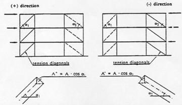
Under gravity load conditions, only beams and columns shall be considered to resist such loads, without considering the bracing members.
Under seismic action, the entire system shall be considered with only the tension diagonals assumed to react the corresponding given seismic action.
Diagonal members shall meet the
following requirement: 1,5 < ![]() < 1,8
< 1,8
The tension force Nsd should be limited to the yield resistance Np1,Rd of the gross cross-section.
The connections of the diagonals to any member should fulfill the overstrength condition
Rd 1,20 .Npl,Rd
where Npl,Rd is the axial resistance of the diagonal in tension.
In frames with V-bracings, the compression diagonals can be composite and should be designed for the compression resistance computed according to clause 5 of Part 1-1 of Eurocode 3.
In order to satisfy a homogeneous dissipative behaviour of the diagonals, it should be checked that the maximum overstrength Wi defined in paragraph (1) of clause 6.8.4. hereunder does not differ from the minimum value W by more than 20%
Beams and columns with axial forces should meet the following minimum resistance requirement:
NRd (M) 1,20 . (NSd,G +W. NSd,E)
where
NRd(M) buckling resistance of the beam or the column according to Eurocode 3 or 4,
NSd,G axial force in the beam or in the column due to the non-seismic actions included in the combination of actions for the seismic design situation,
NSd,E axial force in the beam or in the column due to the design seismic action multiplied by the importance factor,
Wi minimum value of Wi = Npl,Rdi/NSdi over all diagonals of the braced frame system, where
Npl,Rdi design resistance of diagonal i,
NSdi design value of the axial force in the same diagonal i in the seismic design situation.
In V-bracings the beams should be designed to resist all non-seismic actions without considering the intermediate support given by the diagonals.
Composite frames with eccentric bracings shall be designed so that the dissipative action will occur essentially through yielding in shear of the links. All other members should remain elastic and failure of connections should be prevented.
Columns, beams and braces can be structural steel or composite
The braces, columns and beam segments outside the link segments shall be designed to remain elastic under the maximum forces that can be generated by the fully yielded and/or cyclically strain-hardened beam link.
The analysis of the structure is made on the basis of the section properties defined in 6.4.2
In beams, two different flexural stiffnesses are considered : EI1 for the part of the spans submitted to positive (sagging) bending (uncracked section) and EI2 for the part of the span submitted to negative (hogging) bending (cracked section).
Links shall be made of steel sections, possibly composite with slabs. They may not be encased.
Rules on seismic links and their stiffeners presented in 3.8.2. apply.Links may be long or intermediate with a maximum length e:
e < 2Mp, link/ Vp, link
The definitions of Mp, link and Vp, link are given in 3.8.3(3). For Mp,link, only the steel components of the link section are considered in the evaluation.
When the seismic link frames into a reinforced concrete or an encased column, face bearing plates shall be provided on both sides of the link at the face of the column and in the end section of the link. These bearing plates will be full depth stiffeners provided on both sides of the link ; their combined width will not be less than (bf - 2 tW) ; their thickness will not be less than 0,75 tW or 8 mm. bf and tw are the link flange width and web thickness respectively. Figure 6.5.1.
The design of beam/column connections adjacent to dissipative links should conform to 6.5.4 (10) to (14).
Connections should meet the requirements of steel eccentrically braced frames as in clause 3.8.4.
The members not containing seismic links should comply with the rules presented in 3.8.3, considering the combined resistance of steel and concrete in case of composite elements and the relevant rules for members in 6.6 and in Eurocode4.
Where a link is adjacent to a fully encased composite column, transverse reinforcement meeting the requirements of clause 6.6.5. shall be provided above and below the link connection.
In case of a composite brace under tension, only the cross-section of the structural steel section should be considered in the evaluation of the resistance of the brace.
The provisions in this Section apply to composite structural systems belonging to three types defined in par.6.3.1. Figure 6.10.1.
Structural systems Types 1 and 2 are designed to behave as shear walls and dissipate energy in the vertical steel sections and in the vertical reinforcements .
In structural system Type 1, the story shear forces should not be carried primarily through diagonal compression struts in the concrete infills.
Type 3 is designed to dissipate energy in the shear walls and in the coupling beams.
 Type 1 Steel or composite frame with concrete infills
 Type 2 Concrete walls
reinforced by encased vertical steel sections.
 Type
3 Concrete shear wall coupled by steel or
Type
3 Concrete shear wall coupled by steel or
composite beams.
Partially encased steel boundary element used as columns in system Type 1 and Type 2. Details of transverse steel belong to structure ductility class S
Fully encased composite boundary element used as columns in systems type 1 and Type 2
Details of transverse steel belong to structure ductility class S
Detail of framing of a steel coupling beam into a reinforced concrete wall with composite boundary member; details of transverse steel belongs to structures ductility class S.
Details of framing of a steel coupling beam into a reinforced concrete wall; details of transverse steel belong to structure ductility class S.
The analysis of the structure is made on the basis of the section properties defined in Section 2 of this Part 1.3. for concrete walls and in 6.4.2. for composite beams.
Two levels I and S of ductility can be considered, for which two different values of the behaviour factor q are defined in fig. 6.3.1.
In structural system Type 1 and Type2, when vertical encased or partially encased structural steel sections function as boundary members of reinforced concrete infill panels, the analysis will be made considering that the earthquake action effects in these vertical boundary elements are axial forces only. These axial forces are determined assuming that :
the shear forces are carried by the reinforced concrete wall
the entire gravity and overturning forces are carried by the shear wall acting composedly with the vertical boundary members.
In structural system Type 3, if composite coupling beams are used, two different flexural stiffnesses are considered : EI1 for the part of the spans submitted to positive bending moment (uncracked section) and EI2 for the part of the span submitted to a negative bending moment (cracked section).
Alternatively the analysis can be made considering for the entire composite coupling beams an equivalent moment of inertia Ieq constant on their entire spans:
Ieq = 0.6 I1 + 0.4 I2.
The reinforced concrete of infill panels in Type 1 and wall in Types 2 and 3 shall meet the requirements of Chapter 2 of this Part1-3.
Partially encased steel sections used as boundary members of reinforced concrete panels shall belong to a class of cross section related to the behaviour factor of the structure as indicated in 6.6.1.
Fully encased structural steel sections used as boundary members in reinforced concrete panels shall be designed to meet the requirements of 6.6.4.
Partially encased structural steel sections used as boundary members of reinforced concrete panels shall be designed to meet the requirements of 6.6.5. and 6.6.7.
Headed shear studs or welded reinforcement anchors shall be provided to transfer vertical and horizontal shear forces between the structural steel of the boundary elements and the reinforced concrete.
Coupling beams shall have an embedment length into the reinforced concrete wall sufficient to develop the maximum possible combination of moment and shear generated by the bending and shear strength of the coupling beam. The embedment length shall be considered to begin inside the first layer of confining reinforcement in the wall boundary member Figure 6.10.3. The embedment length shall not be less than 1,5 times the height of the coupling beam.
The design of the connection of the steel part of coupling beams in order to assure the transfer of loads between the coupling beam and the wall shall meet the requirements of Chapter 3 of this Part 1-3.
The design of beam/wall connections should conform to 6.5.4 (10) to (14).
The vertical wall reinforcements, defined in 6.5.4 (12) with design axial strength equal to the shear strength of the coupling beam, shall be placed over the embedment length of the beam with two-thirds of the steel located over the first half of the embedment length. This wall reinforcement shall extend a distance of at least one anchorage length above and below the flanges of the coupling beam. It is permitted to use vertical reinforcement placed for other purposes, such as for vertical boundary members, as part of the required vertical reinforcement. Transverse reinforcements should conform to 6.5.4(14).
Transverse reinforcements for confinement of the composite boundary members, either partially or fully encased, shall extend to a distance of 2 h. into the concrete walls as sketched in fig 6.10.2 ; h is the depth of the boundary element in the plane of the wall.
The requirements to links in frames with eccentric bracings apply to coupling beams.
Composite steel plate shear walls are designed to yield through shear of the steel plate.
The steel plate shall be adequately stiffened by encasement and attachment to the reinforced concrete, so that the shear resistance of the steel plate is:
![]()
where
![]() is the design yield
strength of the place
is the design yield
strength of the place
![]() is the horizontal
area of the plate
is the horizontal
area of the plate
Figure 6.11.1. Possible sections of steel shear walls
The analysis of the structure is made on the basis of the materials and section properties defined in 6.4.2 and 6.6.
It will be checked that :
VSd < VRd
Where
VRd is computed according to 6.11.1.(3).
The connections between the plate and the boundary members (columns and beams) as well as the connections between the plate and the concrete encasement will be designed such that full yield strength of the plate can be developed.
The steel plate shall be continuously connected on all edges to structural steel framing and boundary members with welds and/or bolts to develop the yield strength of the plate in shear.
The boundary members shall be designed to meet the requirements of Section 6.10.
Openings in the steel plate shall be stiffened as required by analysis.
For the control and design of construction, Section 3.12 of Part 1.3 applies.
(1)P For the design of timber buildings Eurocode 5 applies. The following rules are additional to those given in Eurocode 5.
(1)P The following terms are used in this chapter with the following meanings:
Static ductility: Ratio between the ultimate deformation and the deformation at the end of elastic behaviour evaluated in quasi-static cyclic tests (see 4.3.(4)P).
Semi-rigid joints: Joints with significant flexibility, the influence of which has to be considered in structural analysis according to Eurocode 5 (e.g. dowel-type joints).
Rigid joints: Joints with negligible flexibility according to Eurocode 5 (e.g. glued solid timber joints).
Dowel-type joints: Joints with dowel-type mechanical fasteners (nails, staples, screws, dowels, bolts etc.) loaded perpendicular to their axis.
Carpenter joints: Joints, where loads are transferred by means of pressure areas and without mechanical fasteners (e.g. skew notch, tenon, half joint).
(1) P Earthquake-resistant timber buildings shall be designed according to one of the following concepts:
a) Dissipative structural behaviour
b) Non- dissipative structural behaviour
In concept a) the capability of parts of the structure (dissipative zones) to resist earthquake actions out of their elastic range is taken into account. When using the design spectrum defined in clause 4.2.4 of Part 1-1, the behaviour factor q is taken greater than 1,0. The value of q depends on the structural type (see 4.3).
(3)P Dissipative
zones shall be regarded as located in joints and connections with mechanical fasteners,
whereas the timber members themselves shall be regarded as behaving
elastically.
The properties of dissipative zones shall be determined by tests either on single joints, on whole structures or on parts thereof according to EN XX . Provisions for avoiding such tests are given in 4.3.(5).
In
concept b) the action effects - regardless of the structural type -
are calculated on the basis of an elastic global analysis without taking into
account non-linear material behaviour. When using the design spectrum defined
in clause 4.2.4 of Part 1-1, the behaviour factor q may not be greater then 1,5.is taken equal
to 1,0.
(1) P Clauses 3, 6 and 7 of Part 1-1 of Eurocode 5 apply. With respect to the properties of steel elements, clause 3 of Part 1-1 of Eurocode 3 applies.
(2) P When using the concept of dissipative structural behaviour, the following provisions apply:
a) Only materials and mechanical fasteners providing appropriate low cycle fatigue behaviour may be used in joints regarded as dissipative zones.
b) Glued joints shall be considered as non-dissipative zones.
c) Carpenter joints may only be used when they can provide sufficient energy dissipation capacity , without presenting risks of brittle failure in shear or tension perpendicular to the grain.. The decision on their use shall be based on appropriate test results.
ClauseParagraph
(2) a) is deemed to be satisfied if clause 4.3 (4) is fulfilled.the following
is met:
When tested according to EN XX1
joints shall be verified to have
appropriate low cycle fatigue properties under large amplitudes to ensure a
sufficient ductility in respect to their intended deformational mechanism and
to justify the q-value assumed in the analysis (see 4.3.(4)).
For
sheathing-material in shear walls and diaphragms, clauseparagraph
(2) a) is deemed to be satisfied, if the following conditions are met:
a) Particleboard-panels have a density of at least 650 kg/m3.
b) Plywood-sheathing is at least 9 mm thick.
c) Particleboard - and fibreboard-sheathing are at least 13 mm thick.
(5)P Steel material for connections shall comply with the following conditions:
a) All connection elements made of cast steel shall fulfill the relevant requirements in Eurocode 3 and in section 3 of this Part.
b) The ductility properties of the connections between the sheathing material and the timber framing in type C and D structures (see 4.3) shall be tested for compliance with 4.3.(4) by cyclic tests on the relevant combination of sheathing material and fastener.
(1) P According to their ductile behaviour and energy dissipation capacity under seismic actions timber buildings shall be assigned to one of the four types A - D given in table .1 with the corresponding behaviour factors.
Table .1: Structural types and behaviour factors
|
Type |
Description of type |
q |
Examples of structures |
|
A |
|
|
Cantilever Isostatic beam |
|
|
Structures having low capacity to dissipate energy |
|
Beams Arches with two or three pinned joints Trusses joined with connectors or rings Trusses with bolted joints Trusses with nailed joints |
|
B |
Structures having medium capacity to dissipate energy |
2.5 |
Wall panels with glued diaphragms, connected with nails and bolts Trusses with bolted joints Hyperstatic portal frames with doweled and bolted joints |
|
C |
Structures having good capacity to dissipate energy |
3 4 |
Trusses with bolted joints Trusses or wall panels with nailed joints Hyperstatic portal frames with doweled and bolted joints Wall panels with nailed diaphragms, connected with nails and bolts. |
|
|
|
|
|
|
|
|
|
|
|
|
|
|
|
|
|
|
|
|
Examples of structural systems belonging to these different types are given in fig. 4.1.
If the building is non-regular in elevation (see clause 2.2.3 of Part 1-2) the q-values listed in table .1 should be reduced by 20% (but need not be taken less than q = ).
(4) P In
order to ensure that the given values of the behaviour factor can be used, the
dissipative zones shall be able to deform plastically for at least three fully
reversed cycles at a static ductility ratio of 4 for type B structures and at a static
ductility ratio of 6 for type C and D structures
without more than a 20% reduction of their resistance.
The provisions of paragraph (4) above and of 4.2.(2) a) and 4.2.(5) b) may be regarded as satisfied in the dissipative zones of all structural types if the following provisions are met:
a) In doweled and nailed timber-to-timber and steel-to-timber joints with one or two shear planes only, the minimum thickness of the connected members is 8 d and the dowel-diameter does not exceed 12 mm.
b) b) In
shear
walls and diaphragms, the connection of sheathing to the timber framing
of diaphragms the sheathing material is wood-based with a and the minimum
thickness of the sheathing material is 4 d, where d does not exceed 3,0 mm.
In that case, reduced values for the behavior factor q, as given in Table .2, shall be used.
Table 8.2 : Types of structures and reduced behaviour factors
|
Types of structures |
Behaviour factor q |
|
Portal frames with doweled and bolted joints Shear wall panels with nailed diaphragms |
|
Behaviour factors different from those presented in table 4.1 may be used for specific structures, if their validity is demonstrated on the base of analytical simulations and tests under a representative number of earthquakes (see clause 4.3.2 of Part 1-1).
) For structures having different and independent properties in the x - and y - directions (see fig. .2), different q-factors may be used for the calculation of the seismic action effects in each main direction.
(1)P In the analysis the slip in the joints of the structure shall be taken into account.
(2)P An EO-modulus-value for instantaneous loading (10% higher than the short term one) shall be used.
Floor diaphragms may be considered rigid in the structural model without further verification, if
a) the detailing rules for horizontal diaphragms given in 4.5.3 are applied
and
b) their openings do not significantly affect the overall in-plane rigidity of the floors.
(1)P The detailing rules given in 4.5.2 and 4.5.3 apply for earthquake-resistant parts of structures designed according to the concept of dissipative structural behaviour.
(2)P Structures with dissipative zones shall be designed so that these zones are located mainly in those parts of the structure where yielding or local buckling or other phenomena due to hysteretic behaviour do not affect the overall stability of the structure.
(1)P Compression members and their connections (e.g. carpenter joints), which may fail due to deformations caused by load reversals, shall be designed in such a way that they are prevented from separating and remain in their original position.
(2)P Bolts and dowels shall be tightened and tight fitted in the holes. Large bolts and dowels (d > 16 mm) shall not be used in timber-to-timber and steel-to-timber connections, except in combination with timber connectors.
Dowels, Smooth smooth nails
and staples should not generally be used without additional
provision against withdrawal. They are however admissible in diaphragms for the
connection of sheathings to the timber framing (see 4.3.(4) b)) and in
secondary members.
(4)In the case of tension perpendicular to the grain, additional provisions should be met to avoid splitting, as for instance shown in fig. .3.
(1)P For horizontal diaphragms under seismic actions clause 5.4.2 of Part 1-1 of Eurocode 5 applies with the following modifications:
a) Paragraphs (2) and (6) shall not be applied.
b) Contrary to paragraph (5) the distribution of the shear forces in the diaphragms shall be evaluated by taking into account the in-plan position of the lateral load resisting vertical elements.
(2)P All sheathing edges not meeting on framing members shall be supported on and connected to blocking (see fig. 4.4). Blocking shall also be provided in the horizontal diaphragms above the lateral load resisting vertical elements (e.g. walls).
(3)P The continuity of beams and especially of headers shall be ensured in areas of diaphragm-disturbances.
(4)P Without
intermediate transverse blocking over the full height of the beams, the
height-to-width ratio (h/b) of the timber beams should be less than 4.The
slenderness of beams shall be limited to b/h < 4.
(5)P In
seismic zones with ag > [0,2] g the spacing of fasteners in areas of discontinuity shall be
reduced to
75% but by dividing by a factor of 1,3 but not
less than the minimum spacing given in Eurocode 5 (see fig. .4).
(6)P When floors are considered as rigid in plan for structural analysis, there shall be no change of span-direction of the beams over supports, where horizontal forces are transferred to vertical elements (e.g. shear-walls).
(1)P Combinations of actions should be determined according to Clause 4.4 of Part 1-1.
( )P The strength values of the timber material shall be determined taking into account the kmod-values for instantaneous loading according to clause 3.1.7 of Part 1-1 of Eurocode 5.
)P For ultimate limit state verifications of
structures designed according to the concept of non - dissipative structural
behaviour (Structures
Type A), the partial safety factors for material properties gM for fundamental accidental load
combinations from table 2.3.3.2 of Eurocode 5 apply.
)P For ultimate limit state verifications of
structures designed according to the concept of dissipative structural
behaviour (Structures
Type B and C), the partial safety factors for material properties gM for accidental fundamental load
combinations from table 2.3.3.2 of Eurocode 5 apply.
)P In order to ensure the development of cyclic yielding in the dissipative zones, all other structural members and connections shall be designed with sufficient overstrength. This overstrength requirement applies especially for
- anchor-ties and any connections to massive subelements,
connections between horizontal diaphragms and lateral load resisting vertical elements.
- carpenter joints do not present risks of brittle failure if the verification of the shear stress according to EC 5 is made with an extra safety factor of 1.3.
(1)P The provisions given in Part 1-1 and in Eurocode 5 apply.
(2)P In accordance to paragraph 2.2.4.3.(2) of Part 1-1 the following structural elements shall be identified on the design drawings and specifications for their special control during construction shall be provided:
- anchor-ties and any connections to massive subelements,
- diagonaI tension steel trusses used for bracing,
connections between horizontal diaphragms and lateral load resisting vertical elements,
connections between sheathing panels and timber framing in horizontal and vertical diaphragms.
(3)P The special construction control shall refer to the material properties and the accuracy of execution.
(1) P This section applies to the design of buildings in unreinforced, confined and reinforced masonry in seismic regions.
(2) P For the design of masonry buildings Eurocode 6 applies. The following rules are additional to those given in Eurocode 6.
(1) P In order to avoid local brittle failures units with formed holes shall meet the following requirements:
a) the units have not more than [50] % by volume of formed holes,
b) the minimum thickness of shells is [15] mm,
c) vertical webs in hollow and cellular units extend over the entire horizontal length of the unit.
Types of units different from the above can be used in reinforced masonry systems provided the prescribed tests (see 5.5.5) prove that the ductility requirements to the walls inherent to the system are met.
In zones of low seismicity (see clause 4.1.(4) of Part 1-1) National Authorities may allow the use of units different from the above.
(1) P The normalised compressive strength of masonry units, derived in accordance with clause 3.1.2.1 of Part 1-1 of Eurocode 6, shall not be less than the following values:
normal to the bed face: fb = 2,5 N/mm2
parallel to the bed face
in the plane of the wall: fbh = N/mm2
(1) P For unreinforced and confined masonry only mortars type M5 or stronger are allowed.
Depending on the seismicity of the region and the importance of the building for unreinforced and confined masonry National Authorities may allow the use of mortars of lower resistance.
(3) P For reinforced masonry only mortars type M10 or stronger are allowed.
(1) P Except in zones of low seismicity perpend joints shall be fully filled with mortar.
The low tensile strength and low ductility of unreinforced masonry impose the limitation of its use in areas of high seismicity. However, its association with reinforcing steel can provide higher ductility and limit the strength degradation under cyclic actions. such improved properties may be taken into account in the design.
(2) P Depending on the masonry type used for the seismic resistant elements masonry buildings shall be assigned to one of the following types of construction:
a) unreinforced masonry construction,
b) confined masonry construction,
c) reinforced masonry construction,
d) construction with reinforced masonry systems.
For types a) to c) the values of the behaviour factor q , depending on the stiffness assumptions used within the structural analysis,, are given in table .1.
Editorial Note: This matter of the stiffness assumption is still under discussion
Table 9.1: Types of construction and behaviour factor
|
Type of construction |
Behaviour factor q (using uncracked stiffness) |
Behaviour factor q (using one half of gross section uncracked elastic stiffness) |
|
Unreinforced masonry |
|
|
|
Confined masonry |
|
|
|
Reinforced masonry |
|
|
(4) P For buildings constructed with reinforced masonry systems the values of the behaviour factor q shall be derived from the results of the ductility tests referred to in 9.5.5.
(1) P The structural model of the building shall adequately represent the stiffness properties of the entire system.
(2) P The stiffness of the structural elements shall be evaluated considering both their flexural and shear deformability and, if relevant, their axial deformability. . Uncracked elastic stiffness may be used for analysis or, more realistically, cracked stiffness in order to account for the influence of cracking on deformability. Depending on the stiffness assumption in use, specifically appropriate values of the behaviour factor q shall be used.
The cracked bending and shear stiffness may be taken as one half of the gross section uncracked elastic stiffness. Other, more accurate stiffness properties can be used if substantiated by a rational analysis. For the cases, that the full or one half of the gross section uncracked elastic stiffness is used, table 5.1. gives adequate values of the behaviour factor q.
) Floor diaphragms may be considered rigid in the structural model without further verification, if
a) they consist of reinforced concrete according to section 2 of this Part
and
b) their openings do not significantly affect the overall in-plane rigidity of the floors.
) In the structural model masonry spandrels may be taken into account as coupling beams between two wall elements, if they are regularly bonded to the adjoining walls and connected both to the floor tie beam and to the lintel below.
) If the structural model takes into account the coupling beams, a frame analysis can be used for the determination of the action effects in the vertical and horizontal structural elements.
) The distribution of the total base shear among the walls, as obtained by the linear analysis described in clause 3.3.1 of Part 1-2, may be modified, provided that global equilibrium is satisfied and the shear in any wall is neither reduced more than [30] % nor increased more than [50] %.
(1) P Masonry buildings shall be composed of floors and walls, which are connected in every direction.
(2) P The connection between the floors and walls shall be adequately provided by steel ties or reinforced concrete ring beams.
Any type of floors may be used, provided the general requirements of continuity and effective diaphragm action are satisfied.
(4) P Shear walls shall be provided at least in two orthogonal directions.
(5) P The shear walls shall comply with the geometric requirements given in table 9.2.
Table 9.2: Geometric requirements for shear walls
|
Masonry type |
t |
hef/t |
h/1 |
|
Unreinforced, with natural stone units |
> mm |
< |
< |
|
Unreinforced, with manufactured stone units |
mm |
< |
< |
|
Unreinforced, with manufactured stone units, in zones of low seismicity |
> |
< |
< |
|
Confined masonry |
> |
< |
< |
|
Reinforced masonry |
> |
< |
No restriction |
|
The symbols used in this table have the following meaning: t thickness of the wall, hef effective height of the wall (see clause 4.4.4 of Part1-1 of Eurocode 6), h greater clear height of the openings adjacent to the wall, l length of the wall |
|||
(1) P In seismic zones with ag > [0,30].g unreinforced masonry is not allowed for seismic resistant elements in buildings having more than two storeys.
(2) P Horizontal concrete beams or - alternatively - steel ties shall be placed in the plane of the wall at every floor level and in any case spaced not more than [4] m.
(3) P The horizontal concrete beams shall have a longitudinal reinforcement with a cross-section of not less than [200] mm2.
(1) P The horizontal and vertical confining elements shall be bonded together and anchored to the elements of the main structural system.
(2) P In order to obtain an effective bond between the confining elements and the masonry, the concrete of the confining elements shall be cast after the masonry has been built.
(3) P The cross-section of both horizontal and vertical confining elements shall be not less than [150x150] mm2.
(4) P Vertical confining elements shall be placed
at both sides of any wall opening with an area of more than [1,5] m2,
at every intersection between walls,
within the wall if necessary in order not to exceed a spacing of [4] m between the confining elements.
(5) P Horizontal confining elements shall be placed in the plane of the wall at every floor level and in any case spaced not more than [4] m.
(6) P In each vertical and horizontal confining element the cross-section of the reinforcement shall not be less than [240] mm2. The reinforcement shall be contained by regularly spaced stirrups.
(7) P The continuity of the reinforcement shall be achieved by [60] diameters overlaps
(1) P Horizontal reinforcement shall be placed in the bed joints or in suitable grooves in the units, with a vertical spacing not exceeding [600] mm.
(2) P Special units with recesses shall accommodate the reinforcement needed in the lintels and parapets.
(3) P Reinforcing steel bars of not less than [4] mm diameter, bent around the vertical bars at the edges of the wall, shall be used.
(4) P The minimum percentage of horizontal reinforcement in the wall, referred to the gross area of the section, shall be not less than [0,05] %.
(5) P High percentages of horizontal reinforcement leading to compressive failure of the units prior to the yielding of the steel, shall be avoided.
(6) P Vertical reinforcement shall be located in appropriate pockets, cavities or holes in the units.
(7) P Vertical reinforcements with a cross-section not less than [400] mm2 shall be arranged
at both free edges of every wall element,
at every wall intersection,
within the wall if necessary in order not to exceed a spacing of [4] m between such reinforcements.
(8) P The minimum percentage of vertical reinforcement spread in the wall, referred to the gross area of the section, shall be not less than [0,10]%.
(9) P The parapets and lintels shall be regularly bonded to the masonry of the adjoining walls and linked to them by horizontal reinforcement.
Using industrially produced reinforced masonry systems, consisting of masonry units with pockets or grooves to accommodate reinforcement, the provisions in 5.2.1.(1) and partially in 5.5.4 may be disregarded provided the system is justified experimentally and the appropriate European Technical Approval is obtained.
(1) P For buildings satisfying the rules for "simple masonry buildings" given in 5.7.2 the safety against collapse is deemed to be verified without an explicit safety verification.
(2) P For the verification of safety against collapse according to clause 4.2.2 of Part 1-2, the design resistance of each structural element shall be evaluated considering clauses 4.4, 4.5 and 4.7 of Part 1-1 of Eurocode 6.
For the verification of safety against out-of-plane collapse the method described in clause 4.6.2.3 of Part 1-1 of Eurocode 6 may be used for guidance when determining the design resistance.
(4) P In ultimate limit state verifications the partial safety factors gM for masonry properties given in table 5.3, depending on the categories of manufacturing control and of execution as defined in Part 1-1 of Eurocode 6, shall be used.
Table 9.3: Partial safety factors gM for masonry properties
|
gM |
Category of execution |
|||
|
A |
B |
C |
||
|
Category of manufacturing control |
A |
|
|
|
|
B |
|
|
|
|
(5) P The partial factor gS for reinforcing steel shall be taken equal to 1,0
(1) P Buildings complying with the provisions given in 5.2 and 5.5 as well as with the rules given in 5.7.2 below may be classified as simple masonry buildings.
For such buildings an explicit safety verification is not mandatory (see 5.6.(1)).
The number of storeys above ground does not exceed the values given in table 9.4.
Table 9.4: Allowed number of storeys above ground
|
Design ground acceleration ag |
< 0,20 g |
> g |
> g |
|
Unreinforced masonry |
|
|
|
|
Confined masonry |
|
|
|
|
Reinforced masonry |
|
|
|
In zones of low seismicity (see clause 4.1.(4) of Part 1-1) National Authorities may allow a greater number of storeys above ground.
The plan configuration of the building fullfills the following conditions:
a) the plan is approximately rectangular,
b) the ratio between the length of the small and the length of the long side ids not less than
c) the projections or recesses from the rectangular shape are not greater than % of the length of the side parallel to the direction of the projection.
(4) The shear walls of the building fulfill the following conditions:
a) the building is stiffened by shear walls which are arranged almost symmetrically in plan in two orthogonal directions,
b) a minimum of two parallel walls is placed in two orthogonal directions, the length of each wall being greater than [30] % of the length of the building in the direction of the wall under consideration,
c) the distance between these walls is greater than [75] % of the length of the building in the other direction.
d) at least [75] % of the vertical loads are supported by the shear walls.
In zones of low seismicity the wall length required in paragraph (4) b) above may be provided by the cumulative length of the shear walls (see 5.5.1.(5)) in one axis, separated by openings.
Between adjacent storeys the difference in mass and in horizontal shear wall cross-section in two orthogonal directions does not exceed
At every floor the horizontal shear wall cross-section in two orthogonal directions, given as percentage of the total floor area above the level considered, is not less than the values of table 5.5.
Table 5.5: Minimum horizontal shear wall cross-section, as percentage of the total floor area above the level considered
|
Design ground acceleration ag |
< 0,20 g |
> g |
> g |
|
Unreinforced masonry |
|
|
|
|
Confined masonry |
|
|
|
|
Reinforced masonry |
|
|
|
For unreinforced masonry buildings, walls in one direction are connected with walls in the orthogonal direction at a maximum spacing of [7] m.
Editorial Note: Text to be added later
CONTENTS
GENERAL
1.1 Scope
Scope o f Eurocode 8
Scope of Part 1-1
Further Parts of Eurocode 8
1.2 Distinction between Principles and Application Rules
1.3 Assumptions
1.4 Definitions
Terms common to all Eurocodes
Further terms used in Part 1-1
1.5 S.I. Units
1.6 Symbols
General
Further symbols used in Part 1-1
1.7 Reference Codes
PERFORMANCE REQUIREMENTS AND COMPLIANCE CRITERIA
2.1 Fundamental requirements
2.2 Compliance Criteria
General
Ultimate limit state
Serviceability limit state
Specific measures
Design
Foundations
Quality system plan
GROUND CONDITIONS AND SEISMIC ACTION
3.1 Ground conditions
Classification of subsoil conditions
3.2 Seismic action
Seismic zones
Basic representation of the seismic action
General
Elastic response spectrum
Peak ground displacement
Design spectrum for elastic analysis
Alternative representations of the seismic action
Time - history representation
General
Artificial accelerograms
Recorded or simulated accelerograms
Spatial model of the seismic action
Combinations of the seismic action with other actions
DESIGN OF BUILDINGS
4.1 General
Scope
Symbols
Symbols and definitions
General
Further symbols used in Part 1-3
Latin upper case symbols
Latin lower case symbols
Greek symbols
4.2 Characteristics of earthquake resistant buildings
Basic principles of conceptual design
General
Structural simplicity.......... ..... ...... .......... ..... ...... .......... ..... ...... .
Uniformity and symmetry
Bi-directional resistance and stiffness
Torsional resistance and stiffness
Diaphragms at storey level
Adequate foundation.......... ..... ...... .......... ..... ...... .......... ..... ......
Structural regularity
General
Criteria for regularity in plan
Criteria for regularity in elevation
4.3 Primary and secondary members
4.4 Structural analysis
Modelling
Accidental torsional effects
Methods of analysis
General
Simplified modal response spectrum analysis
General
Base shear force
Distribution of the horizontal seismic forces
Torsional effects
Multi-modal response spectrum analysis
General
Combination of modal responses
Torsional effects
Alternative methods of analysis
General
Power spectrum analysis
Time-history analysis
Frequency domain analysis
Combination of the components of the seismic action
Horizontal components of the seismic action
Vertical component of the seismic action
Displacement analysis
Non-structural elements
General
Analysis
Importance factors and behaviour factors
3.5.4 Additional measures for masonry infilled frames
3.5.4.1 General
3.5.4.2 Requirements and criteria
3.5.4.3 Irregularities due to masonry infills
3.5.4.3.1 Irregularities in plan
3.5.4.3.2 Irregularities in elevation
3.5.4.4 Damage limitation of infills
Combination coefficients for variable actions
Importance categories and importance factors
4.5 Safety verifications
General
Ultimate limit state
General
Resistance condition
Ductility condition
Equilibrium condition
Resistance of horizontal diaphragms
Resistance of foundations
Seismic joint condition
Serviceability limit state
General
Limitation of interstorey drift
SPECIFIC RULES FOR CONCRETE BUILDINGS
5.1 General
Scope
Definitions
5.2 Design concepts
Energy dissipation capacity and ductility classes
Structural types and behaviour factors
Structural types
Behaviour factors
Horizontal seismic actions
Vertical seismic actions
Design criteria
General
Local resistance criterion
Capacity design criterion
Local ductility criterion
Structural redundancy
Secondary members and resistances
Specific additional measures
Safety verifications
5.3 Design to EC2
Scope
Materials
Behaviour factor
5.4 Design for DC "L"
Geometrical constraints and materials
Material requirements
Geometrical constraints
Beams
Columns
Walls
Specific rules for beams supporting discontinued cut-off vertical elements
Design action effects
General
Special provisions for walls
ULS verifications and detailing
Beams
Bending resistance
Shear resistance
Detailing for local ductility
Columns
Bending resistance
Shear resistance
Detailing for local ductility
Beam-column joints
Walls
Bending resistance
Shear resistance
Detailing for local ductility
5.5 Design for DC "E"
Geometrical constraints and materials
Material requirements
Geometrical constraints
Beams
Columns
Walls
Specific rules for beams supporting discontinued cut-off vertical elements
Design action effects
Beams
Columns
Bending moments
Shear forces
Beam-column joints
Walls
Special provisions for in-plane slender walls
Special provisions for squat walls
ULS verifications and detailing
Beams
Bending resistance
Shear resistance
Detailing for local ductility
Columns
Bending resistance
Shear resistance
Detailing for local ductility
Beam-column joints
Walls
Bending resistance
Diagonal compression failure of the web
Diagonal tension failure of the web
Sliding shear failure
Detailing for local ductility
Coupling elements of coupled walls
5.6 Provisions for anchorages and splices
General
Anchorage of reinforcement
Columns
Beams
Splicing of bars
5.7 Design and detailing of secondary elements
Requirements
5.8 Concrete foundation elements
Scope
Tie-beams and foundation beams
Connections of vertical elements with foundation beams or walls
Cast-in-place concrete piles and pile caps
5.9 Local effects due to masonry or concrete infills
Provisions for diaphragms
SPECIFIC RULES FOR STEEL BUILDINGS
6.1 General
Scope
Definitions
Design concepts
Rules for the design of non dissipative structures.
6.2 Materials
6.3 Structural types and behaviour factors
Structural types
Behaviour factors
6.4 Structural analysis
6.5 Design criteria and detailing rules for dissipative structural behaviour common to all structural types
General
Design criteria for dissipative structures
Detailing rules for elements in compression or bending
Detailing rules for parts or elements in tension
Detailing rules for connections in dissipative zones
Detailing rules for foundations
6.6 Detailing rules for moment resisting frames
Design criteria
Beams
Columns
Beam to column connections
6.7 Detailing rules for frames with concentric bracings
Design criteria
Analysis
Diagonal members
Beams and columns
6.8 Detailing rules for frames with eccentric bracings
Design criteria
Seismic links
Members not containing seismic links
Connections of the seismic links
6.9 Detailing rules for cantilever structures or inverted pendulum structures
Detailing rules for structures with concrete cores or concrete walls, for dual structures and for mixed structures.
Structures with concrete cores or concrete walls
Dual structures
Mixed structures
Safety verifications
Control of design and construction
SPECIFIC RULES FOR STEEL - CONCRETE COMPOSITE BUILDINGS
7.1 General
Scope
Design concepts
Rules for the design of non dissipative structures.
7.2 Materials
Concrete
Reinforcing steel
Steel sections
7.3 Structural types and behaviour factors
Structural Types
Behaviour factors
7.4 Structural analysis
Scope
Stiffness of sections
Diaphragms
7.5 Design criteria and detailing rules for dissipative structural behaviour common to all structural types.
General.
Specific criteria for dissipative structures
Plastic resistance of dissipative zones
Detailing rules for composite connections in dissipative zones
Detailing rules for foundations.
7.6 Detailing rules for members
General
Steel beams composite with slab.
Effective width of slab.
Fully Encased Composite Columns
Partially-encased columns
Filled Composite Columns
Partially-encased beams
7.7 DESIGN AND DETAILING RULES FOR MOMENT FRAMES
Specific criteria.
Analysis
Detailing rules for beams and columns
Beam to column connections
Condition for disregarding the composite character of beams with slab.
7.8 Design and detailing rules for composite concentrically braced frames
Specific criteria
Analysis
Diagonal members
Beams and Columns
7.9 Design and detailing rules for composite eccentrically braced frames
Specific criteria
Analysis.
Links
Members not containing seismic links.
Design and detailing rules for structural systems made of reinforced concrete shear walls composite with structural steel elements
Specific criteria.
Analysis.
Detailing rules for ductility class I composite walls.
Detailing rules for ductility class I coupling beams.
Additional detailing rules for Ductility Class S.
Design and detailing rules for composite steel plates shear walls
Specific criteria
Analysis
Detailing rules
Control of design and construction
SPECIFIC RULES FOR TIMBER BUILDINGS.......... ..... ...... ...........................
General.......... ..... ...... .......... ..... ...... .......... ..... ...... ......................
Scope
Definitions.......... ..... ...... .......... ..... ...... .......... ..... ...... ..............
Design concepts.......... ..... ...... .......... ..... ...... .......... ..... ...... ....
Materials and properties of dissipative zones
Structural types and behaviour factors.......... ..... ...... .......... ..... ...... ....
Structural analysis.......... ..... ...... .......... ..... ...... .......... ..... ...... .....
Detailing rules.......... ..... ...... .......... ..... ...... .......... ..... ...... ............
General
Detailing rules for connections.......... ..... ...... .......... ..... ...... .............
Detailing rules for horizontal diaphragms.......... ..... ...... ............................
Safety verifications.......... ..... ...... .......... ..... ...... .......... ..... ...... ....
Control of design and construction
SPECIFIC RULES FOR MASONRY BUILDINGS
9.1 Scope
9.2 Materials and bonding patterns
Types of masonry units
Minimum strength of masonry units
Mortar
Masonry bond
9.3 Types of construction and behaviour factors
9.4 Structural analysis
9.5 Design criteria and construction rules
General
Additional requirements for reinforced masonry
Additional requirements for confined masonry
Additional requirements for reinforced masonry
Reinforced masonry systems
9.6 Safety verification
9.7 Rules for "simple masonry buildings"
General
Rules
BASE ISOLATION
The design seismic action is generally selected on the basis of a chosen return period and need not coincide with the maximum event of maximum intensity that may occur at a given site. It is assumed that through proper selection of the value of the return period and proper calibration of the design procedures and associated safety elements, the target probability of failure is satisfied
The model should also account for the contribution of joint regions to the deformability of the building, e.g. the end zones in beams or columns of frame type structures. Non-structural elements, which may influence the response of the main resisting structural system, should also be accounted for.
In reinforced concrete buildings this assumption
may lead to unconservative estimates of the displacements, especially when high
values of the behaviour factor q are assumed. In such cases and if
displacements are critical, a more accurate estimation of the stiffness of the
elements under the seismic action may be necessary with regard to the
displacement analysis according to 3.4.
Because of the essentially non-dissipative behaviour of flat slab frames, additional measures are needed (e.g. the possible combination with other seismic resistant structural systems) and/or additional conditions should be prescribed (such as consideration of the low local ductility available or limitations related to the form and height of the building).
Normally the percentages of shear resistance mentioned in 2.1.2 may be substituted by percentages of shear action effects in the seismic design situation.
Obviously, a single structural wall concentrates its plastic region near its base only; however well designed wall systems and dual systems may still generate energy dissipation at several locations.
As a simplification the conventional curvature ductility factor (CCDF) may be calculated by the following expression:

where
ecu concrete strain at the post-peak 0,85.fck-level of the sc ec diagram; in estimating the ecu-value actual confinement may be taken into account,
esy, k characteristic value of tensile strain of steel at yield,
esu, k characteristic value of uniform elongation of steel at maximum load,
xcu normalised neutral axis depth at the post-peak 85% strength level, when concrete is critical; spalling of concrete cover is taken into account,
xsy normalised neutral axis depth at yielding of steel,
xsu normalised neutral axis depth at steel failure, when the tension plastic strain of steel is critical.
|
