In TriSpectives, you create 3D models using the IntelliShapes you saw in the previous chapter. Your models can be as simple or complex as your imagination and time allow.
This chapter shows you important model-building tools in TriSpectives. We take you through step-by-step exercises to help you acquire a feel for each tool.
For more examples that take you step by step through the model-building process, see Chapter 9 of this guide.
Combining IntelliShapes
Using the Move From-To tool
Using SmartSnap
Using SmartDimensions
Using the TriBall tool
Using the scene grid
Using holes in models
Saving models in catalogs
TriSpectives provides an array of shapes and tools to help you build models. You can simply drag shapes around and over other shapes until the model looks right, or you can take advantage of the program's precision tools to build a model that will fulfill dimensional accuracy requirements.
This chapter shows you how to do both. Before we begin, let's browse through some finished models. These models, from the Showcase catalog, give you an idea of what you can accomplish with TriSpectives.
To get to the TriSpectives Showcase catalog, click the Showcase tab at the right of the window. As you scroll through the items in the catalog, you'll see it contains household appliances, a drum, a microscope, and other strange and wonderful creations.
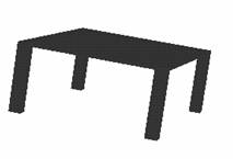
You can use these models as starting points or ideas for your own work. For example, if your graphic designs include furniture, you might study the Dining table model. Since we're going a build a simple table later in this chapter, let's look at the table and see if we can borrow any ideas.
Before you drag the table into the main display, create a new scene.
u To create a new scene:
If TriSpectives is open but you don't have an open WorkBook, choose New from the File menu. Select 3D Scene in the WorkBook Wizard and then select Finish.
If you have an open WorkBook, choose Scene from the Insert menu. In the resulting Insert Scene dialog box, choose As New Scene in WorkBook, and then choose OK.
Now you can drag the Dining table model into the main display from the Showcase catalog.

The table model may first appear in the scene as a facet representation. TriSpectives often simplifies the model so it can more quickly perform the commands you give, such as dragging into the scene. At the facet level, the model appears in a white outline with its anchor. Not all models have to be rendered as facets when they first appear.
If the model needs to be converted into Model mode, when you click on it, TriSpectives asks if you want to regenerate the model. Select Yes. The model then is regenerated as IntelliShapes and appears in blue outline.
As described in Chapter 2, you can control the model at three levels. You can work with it as a whole, work with particular shapes in it, or one surface of a shape. Let's review these editing modes.
|
|
To work with IntelliShapes only, click the Edit IntelliShapes tool shown at left in the illustration. When this tool is on, you select only the IntelliShape you click. To work exclusively with surfaces, choose the Edit Surfaces and Edges tool, the middle tool in the illustration. When this tool is on, you select only the surface you click. To work in Model mode, make sure the Selection tools are inactive. If one is depressed, click it to cancel its selection. By default, TriSpectives assumes you want to work at the model level. |
In Model mode, you can quickly switch between modes by clicking the model. This approach is useful if you need to work at different levels at the same time. By clicking continually in the same spot on a model, you "drill down" to the level you need.
For example, click once on a model to enter Model mode. At this level, all your commands affect the entire model. Click again in the same spot to move to IntelliShape mode and change individual shapes in the model. Click a third time in the same spot to move to Surfaces mode, where you can revise particular surfaces and edges.
The following paragraphs describe each editing mode. Follow along using the Dining table model.
The first time you click the model, you're in Model mode. The entire model is outlined in blue. At this level your actions affect the model as a whole.
The second time you click the model, you select whatever IntelliShape the pointer was over. The sizebox and sizing handles for that shape appear, and the outline changes to white or yellow. In IntelliShape mode, your actions affect only the selected shape. To select a different shape, click it.
Note: Clicking twice is different from double-clicking. To select a shape, click once to go to Model mode, pause, and click again.
The dining table model has three IntelliShapes. One is a slab that represents the table top. We made the other two shapes, the legs, with the 2D drawings tools and then converted them into the third dimension. We'll show you the 2D tools in Chapter 4.
The third time you click the model, you select whatever surface the pointer was over. The selected surface appears outlined in green. In Surfaces mode, your actions affect only the selected surface. To select a different surface, click it.
You can return to Model mode at any time by clicking the scene background and then clicking the model again.
When you drag new shapes from catalogs onto your model, the icon that appears with the dragging pointer gives you a visual clue for which editing mode you're using. For more on these icons, see "Selecting an editing mode" in Chapter 2, "IntelliShapes."
In TriSpectives, the most basic task in model building is assembling two or more shapes into a composite. For example, you might begin a model church with a block to represent the basic structure. Then you could place a pyramid on top of the block to represent the steeple.
The next few procedures explain how to make a simple coffee table. You'll use basic shapes from the Shapes catalog and learn about some of the most powerful model-building tools in TriSpectives.
Before you start the model, add another new 3D scene to your WorkBook. Choose Scene from the Insert menu. When TriSpectives asks where you want to place the scene, specify the WorkBook.
u To begin building a table:
Drag the Slab shape from the Shapes catalog into the scene.
|
|
If the slab is too big or small when it first appears, select the Fit Scene tool and then click in the scene. |
|
|
|
Select the Orbit Camera tool and rotate the slab so you can see most of its bottom side. |
|
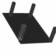
Your view of the slab should resemble the following illustration. You need to see the bottom to anchor the table legs to it.
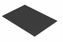
Tabletop
|
|
If the Edit IntelliShapes tool or Edit Surfaces and Edges tool is active, click it to cancel its selection. |
When adding shapes to others, it's sometimes better to be in Model mode. In other situations, it may be better to be in IntelliShape mode. When you drop the legs on your tabletop in IntelliShape mode, for example, the shapes become one model, not a series of discrete shapes. For this example, let's stay in Model mode.
From the Shapes catalog, drag a block into the scene and drop it near a corner on the bottom of the slab.
This block represents one of your table legs. You'll know the bottom of the slab is ready to receive the block when it is outlined in green. For now, don't worry about the precise placement of the block.
Because the bottom of the slab has the same orientation you want for the legs, it's important that you drop the block on it. TriSpectives assumes you want the same orientation when you drop one shape on a particular surface of another.
At the moment we're concerned about the shape of the block. It frankly doesn't look much like a table leg. You could resize the block with the red handles, but you'd still have a block when you were done. To create a proper leg, set the properties of the sizebox.
The Sizebox properties sheet gives you complete control of a shape's dimensions. As explained in the previous example, we were just about to convert a clumsy block into a sleek table leg. A few simple tweaks to the sizebox is all it takes.
u To change a shape's dimensions using the Sizebox properties:
Click on the shape to "drill down" to IntelliShape mode.
In IntelliShape mode, the shape's sizebox and sizing handles appear. The shape's outline changes to white or yellow.
Right-click on the shape.
If you're following along with the example, right-click the block.
Select IntelliShape Properties from the pop-up menu.
From the resulting dialog box, select the Sizebox tab.
The Sizebox properties appear.
Make the following settings in the Sizebox properties sheet:
Length: 40
Width: 40
Height: 120
Under Aspect locks, click Length and width.
These new settings change the shape's dimensions and ensure that the shape's length and width maintain the same aspect ratio, no matter how you revise the shape later.
Because you may have to adjust the leg's height later, do not lock its aspect ratio to other dimensions.
Note: You can also change sizebox dimensions by right-clicking on a sizebox handle in the scene and selecting Edit Value from the pop-up menu. In the resulting window, type a value for the dimension corresponding to the sizebox handle you selected.
Choose OK to change the block into a leg and close the properties sheet.
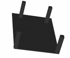
That's more like it. Your table should now look something like the next illustration.
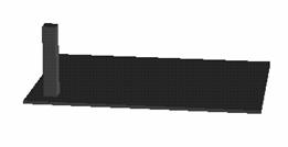
Table with one leg
If the height of the leg still doesn't look right to you, drag it by the resizing handle at the free end and change its height.
If you use one of the sizing handles to change the width or length, these two dimensions change together. The length and width are bound to the aspect lock you set.
You could also go back to the Sizebox properties sheet if you wanted to assign a specific height to the table leg. Once you're happy with the height of the leg, you'll want to create three more just like it. See the next section.
|
Right-drag the shape to copy it elsewhere in the model. |
Many models use the same shape again and again. All you have to do is get the first shape right and then copy it as many times as necessary. If you're working through the table-building exercise from |
the previous section, we still need three more legs.
u To copy a shape to another location in the model:
Right-click on the table leg and then drag it along the underside of the table to another corner.
The precise placement of the leg isn't important now.
Note: If nothing happens when you drag, you need to change one of the shape's Interaction properties. See the next section.
Release the leg when you get close to the second corner.
From the pop-up menu, choose Link Here.
Now your table has two legs. The second leg appears where you released the mouse. Repeat the steps above to create legs for all four corners.
While dragging, you saw the other options on the pop-up menu. Here's a quick explanation of them:
Move Here: Move (but not copy) a shape to another place. This is the same as dragging a shape in IntelliShape mode.
Copy Here: Duplicate a shape at the point you release the mouse button.
Link Here: Create a duplicate shape that's linked to the original one. When you change one shape by resizing it, for instance the other linked shapes change, too. This option saves time if, for example, you want to keep all four legs the same length and size.
Cancel: Forget about your changes and return to the original shape.
Depending on where you dropped the legs, you might have a pretty good-looking table by now. Chances are, however, that they look out of place and unevenly spaced. You need some way to position them more precisely.
TriSpectives has your solution. After a quick discussion of a shape's interaction properties, we'll introduce a couple of the program's most mighty tools: SmartSnap and Move From-To.
The Interaction properties control how a shape acts when you try to manipulate it. In the previous section, we told you to drag a table leg so you could duplicate it in a new location. If nothing happened, follow the steps below.
u To change a shape's Interaction properties:
If necessary, click on the shape to "drill down" to IntelliShape mode.
Right-click on the shape.
If you're following along with the example, right-click the leg.
Select IntelliShape Properties from the pop-up menu.
From the resulting dialog box, select the Interaction tab.
The Interaction properties appear.
Under Drag positioning behavior, choose Slide along surfaces.
The other dragging behaviors are Move freely in space, for when you want to move the shape anywhere in the page or scene, and Fixed position, which means you can't move the shape.
The Interaction properties sheet has two other sets of options. One set controls what happens when you double-click a shape, and one set controls what happens after you drop an object in the page or scene. For more on these options, see "Interaction properties" in Chapter 3, "Dialog boxes," of the TriSpectives Reference Guide.
Choose OK to change the setting and close the properties sheet.
As you drag a shape around a model, how do you know it's in place? Your eyes may be all you need. For instance, if you're creating a model of a piece of Swiss cheese, you can drop the holes wherever you like.
With some models, however, precision is important. You might want to place one shape precisely in the middle of another, or match up their edges.
This positioning process is much easier in TriSpectives than in other 3D software packages. Basically, when you need to position something, you grab it with the mouse and drag it into place. TriSpectives tells you where to stop.
The following steps show you how to use two such tools. In the first example we'll explain the Move From-To tool. Next we'll introduce you to SmartSnap.
Both examples continue the table model we've been building in the previous sections. We want to put the table legs exactly in the corners of the slab.
|
|
Use the Move From-To tool to quickly position shapes. Simply point at a part of one shape and drag it to the corresponding part of the target shape. |
u To reposition a shape with the Move From-To tool:
|
|
Select the Orbit Camera tool and rotate the model so you have a good look at the space between the leg you want to position and its corner destination. |
|
|
|
You may also want to use the Window Zoom tool to further improve your view. |
|
|
|
Choose the Select tool and select the leg you want to position. |
|
Select the Move From-To tool.
Place the mouse pointer on the corner of the leg which is closest to the table's corner.


Selecting a corner with the Move From-To tool
You'll know you're in the right place when a green dot appears on the corner and the pointer becomes a hand.
Click and drag the leg by its corner to the corner of the table.
When you see a green dot appear on the corner of the table, drop the leg.
Click the Move From-To tool again to turn it off.
|
|
The leg is perfectly positioned in the very corner of the table. To prove it, you can use the Orbit Camera tool to check the corner from various angles. |
As you positioned the pointer and dragged the leg, you probably noticed other surfaces and edges change to green. This means you can use the same procedure to align surfaces and edges with the corresponding parts of other shapes.
You could easily position the other legs in their corners using the preceding steps, but we promised to show you SmartSnap. Use it to position the second leg and then decide which tool you want to use to position the other legs.
Like the Move From-To tool you just saw, SmartSnap is a powerful positioning tool. You can line up shapes by their edges or place one shape in the middle of another.
If you've been following along with our table example, we want to use SmartSnap to position a leg exactly in a corner of the table.
u To reposition a shape with SmartSnap:
|
|
Select the Orbit Camera tool and rotate the model so you have a good look at the leg you want to position and the corner destination. |
|
|
|
Be sure you have a view of the two surfaces of the leg that must match the two corner surfaces. You may also want to use the Window Zoom tool to further improve your view. |
|
|
|
Choose the Select tool and select the leg you want to position. |
|
Hold down the Shift key to activate SmartSnap.
Click the leg on the side you want to align with the table edge, and then drag it toward the edge.
It's very important that you grab the leg by the side you want to align. Otherwise, TriSpectives doesn't know how you want to align the shapes. This technique might take a little practice.
When you see SmartSnap's green dotted line, release the leg.
This dotted line is shown in the following illustration.
One side of the leg is now aligned in the corner. Complete the job by positioning the other side of the leg with SmartSnap.


Leg aligned along one table edge
Use SmartSnap to align the second side of the leg in the corner of the table.
Again, click the leg on the side you want to align with the table edge, and then drag it toward that edge. When the SmartSnap indicator appears, you should see dotted lines for both edges of the table.
![]()
![]()
Leg aligned with both edges
When you see SmartSnap's green dotted lines, release the leg.
The leg is perfectly aligned in the corner.
|
|
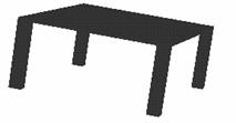
Half the table legs are now correctly positioned. Position the other two using the Move From-To tool or SmartSnap, whichever you prefer. Use the Orbit Camera tool to make the table stand upright. When you're done, it should look like the following illustration. |
|
|
Like the Linking option we used earlier in this chapter to interrelate geometric properties, you can use the Group tool to work with multiple shapes at once. By grouping shapes, you interrelate their style properties. For example, it's much faster to apply a texture once to four grouped shapes than to apply the texture four times. |
To continue with the table-building example we've used throughout this chapter, we'll use the following steps to group the four table legs. Next, we'll apply the same wood texture to the grouped legs.
u To group shapes in a model:
|
|
If the Edit IntelliShapes tool or Edit Surfaces and Edges tool is active, click it to cancel its selection. When both tools are off, you're in Model mode. |
Hold down the Shift key and select the other shapes in the group.
Choose the Group tool.
You can also select Group from the Shape menu. In either case, the shapes are now grouped into one. Any operation you perform on one shape is applied to the others in the group.
Now that you've grouped the table legs, you can apply a wood texture to all of them simultaneously.
You can also finish off the table top. Follow these steps to add colors and textures. For more information, see "Colors," "Textures," and "Transparency" in Chapter 2, "IntelliShapes."
u To add a wood texture to the table legs:
If you haven't already done so, move to Model mode and select the group of shapes representing the table legs.
Open the Wood catalog by clicking its tab.
Drag one of the wood textures onto one of the legs and select OK when the Style dialog box appears.
Because the legs are grouped,
they all receive the wood textures.
For the table top, how about glass? You can simulate a glass look by using a neutral color such as White Smoke from the Colors catalog, and then make the shape transparent.
u To add a glass top to the table:
|
While still in Model mode, select the table top. |
Open the Colors catalog by clicking its tab.
Scroll to near the bottom of the catalog, find White Smoke, and drag it onto the table top.
Right-click on the table top, select Surface Properties from the pop-up menu, and then select the Transparency tab.
In the Transparency properties sheet, drag the Transparency slider bar to about 75 and then choose OK.
The table is finished. It's fairly simple, but it showed you some important model-building tools. In most projects you'll use these tools extensively.
If you've worked through all the examples in this chapter, you'll certainly want to save the table model you labored to make. Simply drag it into a catalog to save it for later use. In fact, you'll use it again in the next section.
u To save a finished model in a catalog:
Create a new catalog.
Choose New from the Catalogs menu to see a blank catalog.
|
|
If the Edit IntelliShapes tool or Edit Surfaces and Edges tool is active, click it to cancel its selection. |
If the Edit IntelliShapes tool is on, for example, you might only drag the selected shape and not the entire model.
Create a complete model by grouping the table top with the four legs.
If you need help with this step, see "Grouping shapes in a model" earlier in this chapter.
Drag the table from the scene and drop it in the new, blank catalog.
A miniature version of the table, or icon, appears in the catalog.
Give the table a name in the catalog.
Click the icon once to select it and then click the UnNamed label to edit it. Enter "Table" in the text box and click outside the icon.
Save your new catalog.
Choose Save As from the Catalogs menu. In the File Name field of the resulting dialog box, type a name such as "My Models" and then choose Save.
In the previous sections you created a 3D model using Model mode. You could have also created the model in IntelliShape mode by observing the following differences:
When you drop shapes on each other in IntelliShape mode, they immediately become one model. You don't need to group the shapes; they're grouped automatically. If you turn off IntelliShape mode by clicking the Edit IntelliShapes tool, the entire collection of shapes appears in one blue outline when you click it.
In many cases, modeling in IntelliShape mode is to your advantage. For example, you can quickly drag such a model into a catalog, provided the Edit IntelliShapes tool is selected.
Because shapes are grouped automatically in IntelliShape mode, the Group tool doesn't work, even if you switch later to Model mode.
In the previous table example, the automatic grouping would have proven a disadvantage, since not all the shapes had the same wood finish. If the entire table, including the top, had the same colors or textures, the automatic grouping would have been an advantage.
To apply style properties such as colors or textures to a model formed in IntelliShape mode, switch to Model mode or Surfaces mode. In Model mode, you change the entire model when you apply a style property. In Surfaces mode, you change only the selected surface. If you had created the table in IntelliShape mode, for example, you could have assigned the same colors and textures using the following steps:
In Model mode, choose a wood texture from the Wood catalog and apply it to the entire table, including the top.
Switch to Surfaces mode and apply the White Smoke color and 75% transparency to each of the six surfaces of the table top.
In all other ways, modeling in Model mode and IntelliShape
mode are the same.
If you want, try creating the table again, this time in IntelliShape mode.
Create a new 3D scene in your WorkBook. Except for the points listed above, the
procedure is the same.
Just as you sometimes need precision tools to align shapes in a model, you might also need to position shapes according to exact distances and angles. For instance, you might want to place two walls of a model room 2.75 inches apart. When you need this kind of control over distances between objects, use SmartDimensions.
Note: SmartDimensions are available with the Professional version of TriSpectives. If you have the basic version of the program, you can measure distances and angles with annotation dimensions. For details, see "Annotation dimensions" in Chapter 6, "Illustration techniques."
To illustrate how to use SmartDimensions, we'll return to our model table. If you saved it to a catalog in the previous section, you can drag it right back into the scene. If you haven't been working along with the examples in this chapter, use the Dining table model from the Showcase catalog.
Once either table is in the scene, let's imagine you need to set up a design for a brochure. In this brochure you need two tables that are exactly 400 centimeters apart.
u To make a copy of the table model:
|
|
If the Edit IntelliShapes tool or Edit Surfaces and Edges tool is active, click it to cancel its selection. |
You must be in Model mode to make a copy of the entire table.
Right-click the table and drag it to the right in the scene.
From the pop-up menu, choose Copy Here.
A duplicate of the table appears. If you want the two tables to look different, you can apply a different wood texture to the legs of the duplicate. These textures are in the Wood catalog.
Now you can place the two tables 400 centimeters apart. Use the following procedure.
u To use SmartDimensions:
|
|
Select the Look At tool and then click the table top of the original table. |
|
|
|
If part of one of the tables disappears, use the Pan Camera tool to make them both fully visible again. Your scene should look something like this: |
|

Two tables
Using the Look At tool helps you measure the distance between objects by giving you a nice, straight plane to work with.
|
|
Choose the Select tool. |
Right-click the copied table and then choose Add SmartDimensions from the pop-up menu.
This option appears on the pop-up menu in Model mode and IntelliShape mode.
In the Add SmartDimensions dialog box, select the Distance measurement.
You also could have selected Angle to separate the tables by a certain angle.
Type the number of SmartDimensions you want and then select OK.
For this example, this number can stay at 1, the default value. To enter a new value, type it in the field called "How many should be added?"
|
|
The table you selected now has a SmartDimension outlined in green. If necessary, use the Pan Camera tool to view the SmartDimension and both table models. |
The next series of steps shows you how to position the SmartDimension line to mark the distance you want to measure. In this example, you want to define a line between the near edges of the two tables.
Drag one end of the SmartDimension by the arrowhead to the near edge of the other table.
When the surface appears highlighted in green, release the mouse button.
Drag the other end of the SmartDimension by the arrowhead until it is over the near edge of the first table.
Make the SmartDimension line as straight as possible. Adjust it until you don't see any crinkles in the line.
Again, release the mouse button when the surface appears highlighted in green. The measurement for the current line appears. Now change it to the measurement you want.
Place your mouse over the green measurement and right-click when the pointer changes to a hand.
From the pop-up menu, select Edit This SmartDimension.
In the next dialog, type the measurement you want in the Value field and then click OK.
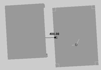
Since we want the two tables to be 400 cm apart, type 400 in the Value field. When you click OK, TriSpectives resets the tables precisely 400 cm apart, as shown in the following illustration.
Note: You can use other units when measuring with SmartDimensions. Select Options from the Tools menu, click the Units tab in the resulting dialog, click the q in the Length field, select the unit you want from the resulting list, and choose OK.
Turn off SmartDimensions.
Place your mouse pointer over the green measurement and right-click when the pointer changes to a hand. From the pop-up menu, select Delete SmartDimension.
|
|
Use the Orbit Camera tool to move the tables until they appear to stand upright in the scene. |
Note: If you'd like more examples of using SmartDimensions, see "Using SmartDimensions for precise positioning" in Chapter 9, "Examples."
This chapter has already shown you many important tools in TriSpectives, but none of them are as versatile as the TriBall tool.
|
Use the TriBall to move models in any direction and around any axis. |
This device gives you complete control over the movement of a shape or model. It lets you move a shape in any direction and, as its name suggests, lets you rotate shapes and models around any of |
their three
axes. The TriBall is ideal for orienting shapes relative to each other and
making your models look realistic. It also provides measurements similar to the
SmartDimensions you saw in the previous section.
|
|
This section introduces you to the many capabilities of the TriBall tool. When you finish, we encourage you to experiment further with the TriBall and master its use. |
If you worked through the earlier examples in this chapter, your table models should still be open in one of your WorkBook documents. To return to the table models, click the appropriate Doc tab at the bottom of the TriSpectives window.
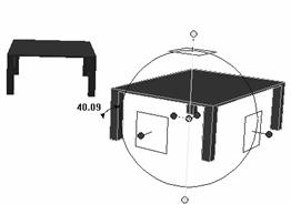
The following procedures show you how to activate the TriBall and reposition the tables for the brochure design you began in the previous section. At the end of that section, the tables looked like the following illustration. If your scene looks different, use the Camera tools to change your view.
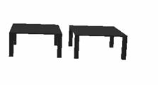
Tables before TriBall
You'll use the TriBall to reorient the tables and create a more dynamic look for your brochure. When you finish this procedure, the tables should look like the next illustration.

Tables after TriBall
u To activate the TriBall tool:
|
|
Choose the Select tool if it isn't already selected. |
Change your editing mode to Model mode, if necessary.
|
|
If the Edit IntelliShapes tool or Edit Surfaces and Edges tool is active, click it to cancel its selection. If you leave the Edit IntelliShapes tool on, for example, you might only reposition the selected shape and not the entire model. |
Select the table on the right.
|
|
To make the TriBall appear over the model, click its icon on the toolbar or choose it from the Tools menu. |
Note that the center of the TriBall appears over the anchor of the model.
![]()
![]()

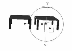
Table and TriBall tool
Because you can do so many things with the TriBall, let's take a moment to explain its controls before you move the tables. Refer to the previous illustration for assistance.
Note that the TriBall has three handles and three planes on its surface, which let you move a model along or around any of its axes. The following paragraphs explain how to move an object in any dimension.
1D (line movement). Drag a 1D handle to move an object along a line. As you drag, a measurement appears next to the handle and shows how far you've moved the object from its starting point.
To specify a distance for movement, right-click the measurement, choose Edit Value from the pop-up menu, and enter the specific distance you want in the resulting dialog box. Keep this feature in mind, along with SmartDimensions, when you need exact distances between objects.
2D (plane movement). When you place the mouse pointer inside a plane, you see four straight arrows, meaning you can drag the shape or model up, down, left, or right.
3D (rotation). When you click a 1D handle, its axis of rotation appears. To rotate an object around this axis, move your mouse pointer within the TriBall. When the pointer changes to a hand and arrow, click and drag to rotate the object around the axis. As you drag, TriSpectives shows the angle of rotation in degrees.
To specify an angle of rotation, right-click the angle measurement, choose Edit Value from the pop-up menu, and enter the specific angle you want in the resulting dialog box.
If you don't want to choose a particular axis, you can rotate the shape in other ways:
Rotation around the center. To rotate the object around the center point of the TriBall, place your mouse pointer on the TriBall boundary. When the boundary turns yellow and the pointer becomes a circular arrow, click and drag.
Rotation around all three axes at once. To rotate the object in any direction at once, move your mouse pointer within the TriBall. When the pointer changes to four circular arrows, click and drag. The effect is like using the Orbit Camera tool on a particular object while all the others remain still.
If you need pinpoint placement of an object, you can also move the TriBall itself. By repositioning the handles, planes, and axes of the TriBall, you move the coordinate system of the object.

![]()
![]()

TriBall repositioning tools
You have two options for moving the TriBall. Use the preceding illustration for assistance.
Drag the center-point handle to move the TriBall's center off the shape's anchor to a new position in the shape. This point is the new center of rotation.
Drag one of the rotation handles to rotate the TriBall itself, not the object. These handles reposition the 1D, 2D, and 3D controls on the surface of the TriBall.
Now that you've been introduced to the TriBall controls, use them to create a more dynamic look for your brochure. Currently the tables are just sitting side by side, and because one was copied from the other, they have the same orientation. In the design world, the technical term for this look is boring. Reorient the table models.
u To reposition the tables using the TriBall:
Select the table on the right, if it isn't already selected.
Drag the table toward the front of the scene.
To do this, place your mouse pointer in the 2D plane on top of the table. When the pointer becomes four straight arrows, drag the table down so it appears to be coming toward you.
Rotate the table on the right about 40 degrees in the direction of the other table.
To do this, click the 1D handle above the plane you just moved. When the axis of rotation appears for the handle, move your pointer inside the TriBall. When the pointer changes to a hand and arrow, drag the table in the direction of the other table. Stop when the angle is about 40 degrees.
Your model should look like the following illustration.
Tables after rotation
Make the angle of rotation exactly 40 degrees.
To do this, right-click the angle measurement and choose Edit Value from the pop-up menu. In the resulting dialog box, enter 40 and click OK.
Drag the 1D handle at the left of the table until part of it seems to be in front of the other table.
Your tables should now look like this.
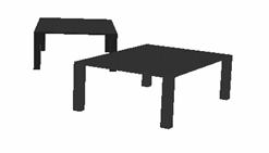
Tables after TriBall
You can use the Camera tools to change your viewpoint until the tables appear to be the right size within the scene.
|
|
We hope you think the tables look better in this orientation. If you don't, keep using the TriBall until you like the scene. When you're done, click the TriBall tool to turn it off. |
The TriBall has one last powerful feature. With a few simple steps, you can make multiple copies of a shape or model, create a uniform spacing between each pair of copied objects, and specify the direction in which the copies appear.
For example, to make the rungs of a chair, you could create one and then copy the rest. You could also make each pair of rungs two inches apart.
For instructions on using the TriBall to create and position multiple copies of shapes and models, see "Using the TriBall for precise positioning in Chapter 9, "Examples."
Another model-positioning tool is the scene grid, a cross-hatched network of solid lines that provide a reference if you must place two or more shapes in the same orientation along an axis. This tool is useful in concert with the TriBall.
In the following example you'll use the scene grid to reposition the tables from the previous exercise. You took the above illustration to your supervisor, and she said to put the tables back the way they were. Apparently she just doesn't appreciate dynamic designs.
Now you must reorient the tables to be parallel to each other, the way they were earlier.
u To display the scene grid:
Right-click in the scene and choose Scene Properties from the pop-up menu.
In the resulting dialog box, click the Show tab.
In the Show properties sheet, select the Scene Grid option.
Select the Scene Grid Dimensions option.
By choosing this option, you display measurements of the distance between an object's anchor and the center of the grid.
Click OK to close the properties sheet.
The scene grid appears. The letters H, W, and L appear in the center of the grid to indicate the axes.
If you don't see the grid, or if it isn't large enough to encompass the models, choose Options from the Tools menu and click the Scene Grid tab in the resulting dialog box. In the Size fields of the Scene Grid properties sheet, type greater values for the Length and Width and then select OK.
Experiment with these settings to create an effective grid. For example, you might have to return to the Scene Grid properties sheet and increase the Line Separation values as well.
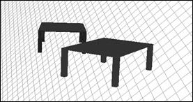
Scene with grid
Once you're happy with the size of the grid and the distance between its lines, you can reorient your model. You'll need the TriBall tool too.
u To orient shapes and models using the scene grid and TriBall:
|
|
Choose the Select tool if it isn't already selected. |
Change your editing mode to Model mode, if necessary.
|
|
If the Edit IntelliShapes tool or Edit Surfaces and Edges tool is selected, click it off. |
|
|
|
Select either table and then Choose the TriBall tool. |
|
Use the TriBall controls to make the table top parallel with one of the horizontal lines of the grid.
If you need help using the TriBall tool, see the previous section.
Choose the Select tool again and then select the other table.
Select the TriBall tool again and use its controls to make the table top parallel with one of the horizontal lines of the grid.
When both table tops are parallel with the grid, they're parallel to each other as well.
Turn off the TriBall tool by clicking its icon on the toolbar again.
Turn off the scene grid.
Use the same procedure you used to turn the grid on. It's the five-step sequence earlier in this section.
We've introduced you to most of the important positioning tools in TriSpectives. This section mentions a few more that you might find handy in some situations:
Attachment points, for joining shapes and models at a point other than the anchor.
Position properties, for repositioning a shape or model's anchor relative to the center of the scene grid.
Anchor properties, for repositioning an anchor on a shape or model.
If you want to experiment with these tools and properties, open a new scene in your WorkBook.
By adding an attachment point to a shape or model, you can join shapes at a point other than the anchor. You can drop an attachment point at any spot on a shape or model, and then attach another shape right on that point.
u To attach shapes and models with attachment points:
Drag a shape into a new scene from the Shapes catalog.
From the Insert menu, choose Attachment Point.
Move the mouse pointer to the scene and click the shape on the spot where you want the attachment point.
A marker appears to show the attachment point.
Drag another shape into the scene from the Shapes catalog and drop it on the attachment point.
The attachment point appears as a green dot when the shape is over it. When you release the mouse, the anchor of the shape is joined to the attachment point of the first shape.
You can also put attachment points on both shapes and join them by those points. Just drag the attachment point of one shape and drop it onto that of the other shape. If you move the target shape, the dropped shape moves as well. If you move the dropped shape, the attachment-point constraint between it and the target shape is broken.
You can also reposition attachment points on a shape or model.
u To reposition an attachment point on a shape or model:
Place your mouse pointer on the attachment point.
When the pointer becomes a hand, right-click the mouse and choose Move Attachment Point from the pop-up menu.
In the resulting dialog box, type values for the distances the attachment point should move from its current position.
You can type values for up to three directions of movement.
Click Apply to see the new location of the attachment point on the shape or model.
You might have to move the dialog box out of the way to see the scene. If necessary, enter new values and click Apply again. When you're satisfied with the position of the attachment point, click OK.
To tilt the attachment point so that a shape or model lands on it at a certain angle, right-click the attachment point and select Spin Attachment Point from the pop-up menu. In the resulting dialog box, type the angle measurement and click OK.
When you add an attachment point to a shape, it receives a new Model properties sheet. To see these properties, right-click the shape in Model mode. Select Model Properties from the pop-up menu and then click the Attachment Point tab.
The resulting dialog lets you reposition the attachment point, just as you can by right-clicking it.
u To delete an attachment point, right-click on it and choose Delete from the pop-up menu.
The Position properties sheet lets you change the position of a shape or model's anchor relative to the center of the scene grid. The shape or model moves in accordance with the anchor's new position. The following procedure shows you how to use the properties sheet.
If you worked through the example in the previous section, you can use the same scene and shapes for the next example. If not, you can create a new scene and drag in a shape from the Shapes catalog.
u To reposition a shape using the Position properties:
Turn on the scene grid and scene grid dimensions.
Right-click the scene background, choose Scene Properties from the pop-up menu, click the Show tab, and select both Scene Grid and Scene Grid Dimensions. Click OK to close the dialog box.
Right-click the shape and choose Model Properties from the pop-up menu.
Click the Position tab.
In the resulting Position properties sheet, type new values for the distances between the shape's anchor and the center of the scene grid.
Note that the current values are the same as those shown in green on the scene grid. You can type new distances for the length, width, and height of the anchor relative to the grid's center.
Click OK to see the new position of the shape.
Note: For more information on the Position properties sheet, see Chapter 3, "Dialog boxes," of the TriSpectives Reference Guide.
Aside from attachment points, the anchor is the spot where shapes join to form models. When you're in model editing mode, the anchor appears as the lone red dot on the shape or model. The Anchor properties let you reposition the anchor, in case you want to drop a second shape in a specific location on the target shape.
If you worked through the example in the previous section, you can use the same scene and shapes for the next example. If not, you can create a new scene and drag in a shape from the Shapes catalog.
u To reposition a shape's anchor:
If necessary, turn off the scene grid.
Right-click the anchor and choose Move Anchor from the pop-up menu.
In the resulting dialog box, type values for the distances the anchor should move.
You can type values for up to three directions of movement.
Click Apply to see the anchor's new location on the shape.
You might have to move the dialog box out of the way to see the scene. If necessary, enter new values and click Apply again. When you're satisfied with the position of the anchor, click OK.
To tilt the anchor so that a shape or model lands on it at a certain angle, right-click the anchor and select Spin Anchor from the pop-up menu. In the next dialog, type the angle measurement and click OK.
You can also change the anchor's position using the Anchor properties sheet. To see these properties, right-click the shape in Model mode. Select Model Properties from the pop-up menu and then click the Anchor tab. The resulting properties sheet lets you reposition the anchor, just as you can by right-clicking it.
Once you complete a model, it has an anchor too. To change the position of a model's anchor, right-click the model in Model mode. Select Model Properties from the pop-up menu and then click the Anchor tab. The resulting properties sheet is identical to the one that appears for shapes.
You can create models by subtracting from shapes as well as by adding to them. Use the hole shapes in TriSpectives to cut grooves, create indentions, and bore holes through the other shapes.
|
Holes have handles and property sheets like any IntelliShape. |
The only difference between holes and other IntelliShapes is that they're negative instead of positive. Holes have shape handles for sizing, just like positive shapes; likewise, if you right-click a hole, |
you see a property sheet. You can use SmartSnap and SmartDimensions with holes as well.
Note: In addition to creating hole shapes, you can construct entire models that are holes. For more information, see "Making negative models" in Chapter 1 of the TriSpectives Reference Guide.
In this section you'll create an earring by dropping a couple of hole shapes on a solid shape. When you're done, the side view of the earring should look like this:

Earring model
|
Use the Camera tools if you need help selecting a hole shape. |
When working with hole shapes, you can get frustrated unless you use the right tools. For instance, the hole shapes can be hard to select if the visible face of a hole's effect is too small. Use the Zoom |
|
|
Camera or Window Zoom tool to move closer to the model and give yourself a larger area to select the hole. |
The following procedure tells you exactly what to do.
u To create an earring hole using hole shapes:
If you don't have an empty 3D scene in your WorkBook, create one.
Click the Shapes tab to see the items in the Shapes catalog.
This catalog contains the TriSpectives hole shapes.
Drag the Rib shape from the catalog and drop it in the scene.
Use the Camera tools to get a good view of a large surface of the rib.
|
|
Use the Look At and Window Zoom
tools until you're looking straight at the broad side of the rib. Position
the rib as shown in the previous illustration. Also, grab the rib by a handle
and resize it to make it look more like the previous illustration |
|
|
|
Select the Edit IntelliShapes tool. |
|
As mentioned earlier in this chapter, IntelliShape mode is often better than Model mode for combining shapes into a model. This is especially true with hole shapes, because the handles give you a visual cue for selecting the hole.
Drag the cylinder hole shape (H Cyl) into the scene and drop it on the broad side of the rib.
Drop it near the end of the bottom point of the rib, as shown in the previous illustration. To give the hole shape the orientation you want, make sure the broad side of the rib turns green before you drop the hole. When you drop the shape, it bores a cylindrical hole in the rib.
Adjust the size and position of the hole so it looks like the one in the previous illustration.
If the cylinder doesn't completely bore through the rib, resize the cylinder using a handle on one of its ends. You can move a hole by dragging it, or resize it by dragging its handles, just like other shapes.
|
To select a hole, click a part of the positive surface formed along the path of the hole. |
In many cases, you need to use the Camera tools before you can select the hole. Otherwise, nothing happens when you try to select it. To make sure you click the hole and not something else, change your viewpoint so you can see one of the inner |
surfaces formed by the hole. This is often easier to do if you select the Window Zoom tool.
|
|
For example, to select the hole in this example, use the Window Zoom tool to close in and then click the area shown by the pointer in the following illustration. |
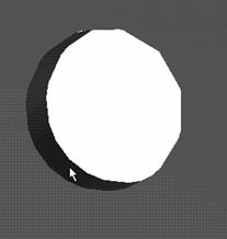
Selecting a hole shape
|
|
Once you've selected the hole shape, you can resize it or drag it to a new location. When you finish, select the Fit Scene tool. Your view moves back to give you a better vantage point, and the hole shape is still selected. |
Note: You can also select the hole shape using the WorkBook browser. See the next section for details.
Drag another cylinder hole shape into the scene and drop it on the rib.
Drop this hole shape above the first hole. The hole should cut a semi-circular swath in the top of the earring, as shown in the illustration at the beginning of this section. If the hole doesn't look right, adjust it using the techniques from Step 7.
If you have trouble selecting a hole shape, you can also use the WorkBook browser. The browser shows everything in your active WorkBook in the form of a tree chart, starting with the WorkBook itself and going down the various levels, from documents to models, and finally to each IntelliShape in the model.
u To open the WorkBook browser, select it from the View menu.
If you've been working along with the examples in this chapter, the browser should look something like this:
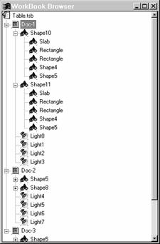
WorkBook browser
When a plus or minus appears to the left of an item in the tree, you can click it to see more or fewer details of the WorkBook. For example, click a plus sign to the left of a model to see all the shapes in it.
The browser provides an easy way to select any of the contents of the open WorkBook. You can also name or rename any of the contents.
u To select an item in the scene from the WorkBook browser, right-click the item's name in the browser, and then choose Select from the pop-up menu.
When you close the browser, the item is selected in the
scene.
It's just as easy to name an item.
u To name an item using the WorkBook browser, click the item's name in the browser, pause, and click it again. When a box appears around the item, type the new name and press Enter.
To close the browser, click the X in its top right corner.
|
Save the whole scene to save a group of models together. |
Earlier in this chapter you saved a completed model by dragging it into a new catalog. If your scene contains more than one model and you want to save them together, you can drag the entire scene into |
a catalog. When you retrieve the scene later by dragging it back from the catalog, it looks the same.
When you save an entire scene, you also save its background. Just like shapes, you can apply colors and textures to the background. If you want to retain these settings for later use, save the scene.
When you save scenes, you can embed them later on the 3D page. In this way, you can put together complex designs by combining groups of models created in different scenes. For more information, see Chapter 6, "Illustration techniques."
The following steps show you how to save a scene to a catalog. As an example, use the two tables you worked with earlier in this chapter.
u To save a finished model in a catalog:
Select the tab for the My Models catalog.
You created this catalog earlier to accommodate your first table model. If you have not been working through the examples in this chapter, create a new catalog by choosing New from the Catalogs menu.
|
|
If the Edit IntelliShapes tool or Edit Surfaces and Edges tool is active, click it to cancel its selection. |
Click the Doc tab for the scene that contains the tables and then drag the tab to the catalog.
The Doc tabs appear at the bottom of the window. After dragging, an icon representing the scene appears in the catalog.
Give the scene a name in the catalog.
Click the icon once to select it and then click the UnNamed label. When a box appears around the label, type "Tables" in the text box and then click outside the icon.
Save the catalog.
If the catalog is new, choose Save As from the Catalogs menu. In the File Name field of the resulting dialog box, type a name such as "My Models" and then choose Save.
If you've already named the catalog and saved it before, choose Save from the Catalogs menu.
If you're interrupted before you can finish your design, you can simply save the entire WorkBook. All the documents you were working on remain in the same state until the next time you can work on them.
u To save all the documents in the WorkBook, select Save from the File menu at the top of the TriSpectives window.
TriSpectives prompts you to name the WorkBook if you're saving it for the first time. TriSpectives also adds a .tsb extension to the file name.
|
