Overview
When designing and implementing a network there are many things to take into consideration in order to insure a reliable and scalable network that will continue to function for many years. Some of these considerations include:
1.1. LAN Switching
1.1.1. Congestion and bandwidth
Technology advances are producing faster and more
intelligent desktop computers and workstations. The combination of more
powerful computers/workstations and network intensive applications have created
a need for network capacity or bandwidth that is much greater than the 10 Mbps
that is available on standard shared Ethernet/802.3 LANs. ![]()
Today's networks are experiencing an increase
in the transmission of large graphic files, images, full-motion video and
multimedia applications, as well as an increase in the number of users on a
network. These factors place an even greater strain on standard Ethernet 10Mbps
bandwidth capacity. ![]()
As more people utilize a network to share
large files, access file servers and connect to the Internet, network
congestion occurs. This can result in slower response times, longer file
transfers and network users becoming less productive due to network delays. To
relieve network congestion, more bandwidth is needed or the available bandwidth
must be used more efficiently. ![]()


1.1.2. Why segment LANs ?
A network can be divided into smaller
units called segments. Each segment uses the Carrier Sense Multiple Access/ Collision
Detection (CSMA/CD) protocol and maintains traffic between users on the
segment. By using segments in a network, fewer users and devices are sharing
the same 10Mbps when communicating to one another within the segment. Each
segment is considered its own collision domain. ![]()
This is an example of a segmented Ethernet network. The entire network has 15 computers (6 file severs and 9 PCs). Without segmenting the network all 15 devices would need to share the same 10Mbps bandwidth and would reside in the same collision domain.
By dividing the network into three
segments, a network manager can decrease network congestion within each
segment. When transmitting data within a segment these five devices are sharing
the 10Mbps bandwidth per segment. ![]()
In a segmented Ethernet LAN data passed between segments is transmitted on the backbone of the network using a bridge, switch, or router. The backbone network is its own collision domain. It uses CSMA/CD to provide a best effort delivery service between segments.


1.1.3. Segmentation with LAN switches
A LAN that uses a switched Ethernet
topology creates a network that behaves like it only has two nodes. They are
the sending node and the receiving node. These two nodes share the 10Mbps
bandwidth between them. This means that nearly all the bandwidth is available for
the transmission of data. A switched Ethernet LAN uses bandwidth so
efficiently, and therefore can provide a faster LAN topology than standard
Ethernet LANs. In a switched Ethernet implementation the available bandwidth
can reach closer to 100%. ![]()
The purpose for using LAN switching is
to ease bandwidth shortages and network bottlenecks between nodes. A LAN switch
is a very high-speed multiport bridge with one port for each node or segment of
the LAN. A switch segments a LAN into microsegments creating collision free
domains from one larger collision domain. ![]()
Switched Ethernet is based on standard Ethernet. Each node is directly connected to one of its ports or a segment that is connected to one of the switch's ports. This creates a 10Mbps bandwidth connection between each node and each segment on the switch. A computer connected directly to an Ethernet switch is its own collision domain and accesses the full 10Mbps.
As a frame enters a switch it is read for the source and/or destination address. The switch then determines which switching action will take place based on what the switch has learned from the information read off the frame. The frame is then switched to its destination.

1) A switch eliminates the impact of collisions through microsegmentation
2) Low latency and high frame-forwarding rates at each interface port
3) Works with existing 802.3(CSMA/CD) compliant network interface cards and cabling

Dedicated paths between sender and receiver hosts
1.1.4. LAN switching overview
LAN switches are considered multiport
bridges with smaller collision domains because of microsegmentation. ![]() Data
is exchanged at high speeds by switching the packet to its destination.
Data
is exchanged at high speeds by switching the packet to its destination.
Switches achieve this high-speed
transfer by reading the destination layer 2 MAC address of the packet much like
a bridge does. ![]()
![]() The
frame is sent to the port of the receiving station prior to the entire frame
entering the switch. This leads to low latency levels and a high rate of speed
for frame forwarding.
The
frame is sent to the port of the receiving station prior to the entire frame
entering the switch. This leads to low latency levels and a high rate of speed
for frame forwarding.![]()
Ethernet switching increases the bandwidth available on a network. It does this by creating dedicated network segments (point to point connections) and connecting those segments in a virtual network within the switch. This virtual network circuit exists only when two nodes need to communicate. This is why it is called a virtual circuit. It exists only when needed and is established within the switch.
Even though the LAN switch creates dedicated, collision-free domains, all hosts connected to the switch are still in the same broadcast domain. Therefore all other nodes connected through the LAN switch will still see a broadcast from one node.
1) Multiport bridge 2) Creates smaller
collision domain 3) Switching and
filtering based on Layer 2 MAC addresses 4) Transparent to upper
layers


1) Enables dedicated access
2) Eliminates collisions and increases capacity
3) Supports multiple conversations at a time


1) Forwards frames based on a forwarding table
2) Operates at OSI Layer 2
3) Forwards frames based on the MAC (Layer 2) address
1.1.5. How a LAN Switch learns addresses
An Ethernet switch can learn the address of each device on the network by:
The switch then adds this information
to its forwarding database. Addresses are learned dynamically. This means that
as new addresses are read they are learned and stored in content addressable
memory (
Each time an address is stored it is
time stamped. This allows for addresses to be stored for a set period of time.
Each time an address is referenced or found in the
1) Learns a station's location by examining the source
address 2) Sends the frame out all ports (except the port the
frame entered from) when the destination address is a broadcast, multicast,
or an unknown address 3) Forwards the frame when the destination is located on
a different interface 4) Filters when the destination is located on the same
interface

Symmetric switching
Symmetric switching is one way of characterizing a LAN switch according to the bandwidth allocated to each port on the switch. A symmetric switch provides switched connections between ports with the same bandwidth, such as all 10 Mbps or all 100 Mbps ports. A symmetric switch is optimized through even distribution of network traffic across the entire network
1) Provides switching between like bandwidth (10/10 or
100/100 Mbps) 2) Multiple simultaneous conversations increase network
throughput

1.1.7. Asymmetric switching
An asymmetric LAN switch provides switched connections between ports of unlike bandwidth, such as a combination of 10 Mbps and 100 Mbps ports. This type of switching is also called 10/100 switching.
Asymmetric switching is optimized for client-server network traffic flows where multiple clients are simultaneously communicating with a server. Simultaneous communication requires more bandwidth dedicated to the switch port that the server is connected to in order to prevent a bottleneck at that port.
Memory buffering in an asymmetric switch is required. It allows traffic from the 100 Mbps port to be sent to a 10 Mbps port without causing too much congestion at the 10 Mbps port.
1) Provides switching between unlike bandwidths (10/100
Mbps) 2) Requires the switch to use memory buffering

1.1.8. Two switching methods
There are two switching modes that can
be selected to forward a frame through a switch. The latency of each of these
switching modes depends on how the switch forwards the frames. The faster the
switch mode the smaller the latency in the switch. To accomplish faster frame
forwarding the switch takes less time to check for errors. The trade off is
less error checking which can lead to a higher number of re-transmissions. ![]()
There are two ways to forward frames
through a switch: ![]()

Cut-through:
Switch checks destination address and immediately begins forwarding frame Store-and-forward:
Complete frame is received before forwarding

Introducing VLANs
LANs are increasingly being divided
into workgroups connected via common backbones to form virtual LAN (VLAN)
topologies. ![]() VLANs
logically segment the physical LAN infrastructure into different subnets
(broadcast domains for Ethernet). This is done so that broadcast frames are
switched only between ports within the same VLAN.
VLANs
logically segment the physical LAN infrastructure into different subnets
(broadcast domains for Ethernet). This is done so that broadcast frames are
switched only between ports within the same VLAN. ![]()
Initial implementations offered a
port-mapping capability. Port-mapping establishes a broadcast domain between a
default group of devices. ![]() Current
network requirements demand VLAN functionality, which will cover the entire
network. This approach to VLANs allows the user to group geographically
separate users in network-wide virtual topologies.
Current
network requirements demand VLAN functionality, which will cover the entire
network. This approach to VLANs allows the user to group geographically
separate users in network-wide virtual topologies.
1) A group of ports or users in the same boradcast domain 2) Can be based on port ID, MAC address, protocol, or
application 3) LAN switches and network management software provide
a mechanism to create VLANs 4) Frame tagged with VLAN ID

A broadcast transmission
consists of a single data packet being sent into the network where it is
copied and sent to every node. The source node addresses packets using a
broadcast address specifying that the packet should be sent to every
possible destination node. The packets are the sent into the network. The
network copies the packets and passes them to every node on the network.


1) Logical networks
independent of their members' physical location 2) Administratively
defined broadcast domain 3) Users reassigned to
different VLAN using software
Frame filtering
Frame filtering is a technique that examines particular information about each frame. The concept of frame filtering is very similar to that commonly used by routers. A filtering table is developed for each switch. The filtering table provides a high level of administrative control because it can examine many attributes of each frame. Depending on the sophistication of the LAN switch, users can be grouped based on station MAC addresses, network-layer protocol types, or application types. Table entries are compared with the frames filtered by the switch. The switch takes the appropriate action based on the entries.
1) A filtering table is
developed for each switch 2) Switches share address
table information 3) Table entries are
compared with the frames 4) Switch takes appropriate
action

Frame tagging
Frame identification (frame tagging) uniquely assigns a user-defined ID to each frame. This technique was chosen by the IEEE standards group because of its scalability.
VLAN frame identification is an approach that has been specifically developed for switched communications. This approach places a unique identifier in the header of each frame as it is forwarded throughout the network backbone. The identifier is understood and examined by each switch. This occurs prior to any broadcasts or transmissions to other switches, routers, or end-station devices. When the frame exits the network backbone, the switch removes the identifier before the frame is transmitted to the target end station. Frame identification functions at Layer 2 require little processing or administrative overhead.
1) Specifically developed for multi - VLAN, interswitched
communication 2) Places unique identifier in header of each frame as
it travels across the network backbone (vertical cabling) 3) Identifier removed before frame exits switch on
nonbackbone links (horizontal cabling) 4) Functions at Layer 2 5) Requires little processing or administrative overhead

1.2.4. VLANs establish broadcast domains
VLANs are an effective mechanism for extending firewalls from the routers to the switch fabric. They also protect the network against potentially dangerous broadcast problems. Additionally, VLANs maintain all of the performance benefits of switching. These firewalls are accomplished by assigning switch ports or users to specific VLAN groups both within single switches and across multiple connected switches. Broadcast traffic within one VLAN is not tr 434r1723e ansmitted outside the VLAN. Conversely, adjacent ports do not receive any of the broadcast traffic generated from other VLANs. This type of configuration substantially reduces the overall broadcast traffic, frees bandwidth for real user traffic, and lowers the overall vulnerability of the network to broadcast storms.
The size of the broadcast domain can be easily controlled. To do so regulate the overall size of its VLANs, restricting the number of switch ports within a VLAN and restricting the number of users residing on these ports. The smaller the VLAN group, the smaller the number of users affected by broadcast traffic activity within the VLAN group.

VLANs plus routers bound broadcasts to domain origin
Port-centric virtual LANs
VLAN membership by port maximizes forwarding performance because:

All nodes attached to the same switch port must be in the same VLAN
1.2.6. Static VLANs
Static VLANs are ports on a switch that the user statically assign to a VLAN. These ports maintain their assigned VLAN configurations until the user changes them. Although static VLANs require changes by the user, they are secure, easy to configure, and straightforward to monitor. This type of VLAN works well in networks where moves are controlled and managed.
1) Statically assigned ports (port-centric) 2) Static VLANs are secure, easy to configure and
monitor

Dynamic VLANs
Dynamic VLANs are ports on a switch that can automatically determine their VLAN assignments. Most switch manufacturers use intelligent management software. Dynamic VLAN functions are based on MAC addresses, logical addressing, or the protocol type of the data packets.
When a station is initially connected to an unassigned switch port, the appropriate switch checks the MAC address entry in the VLAN management database and dynamically configures the port with the corresponding VLAN configuration. The major benefits of this approach are less administration within the wiring closet when a user is added or moved, and centralized notification when an unrecognized user is added to the network. Typically, more administration is required up front to set up the database within the VLAN management software and to maintain an accurate database of all network users
1) VLANs assigned using centralized VLAN management
application 2) VLANs based on MAC address, logical address, or
protocol type 3) Less administration in wiring closet 4) Notification when unrecognized user is added to
network

1.3.1. LAN design goals
The first step in designing a Local Area Network (LAN) is to establish and document the goals of the design. These goals will be particular to each organization or situation. However, general requirements tend to show up in any network design:
1.3.2. Design methodology
The three steps shown in the bold letters below describe a simple model that could be used in network design. The steps of designing the network topology, devising addressing, and naming conventions should be completed in early planning stages. They should not require major changes later.
1. Analyze requirements
2. Develop LAN structure (topology)
3. Set up addressing and routing
What problem are you trying to solve
The decision to use an internetworking device depends on which problems you are trying to solve for your client. Problems may include media contention, transport of new payloads, and network layer addressing issues.
Media contention refers to excessive collisions on Ethernet caused by too many devices, all with a high demand for the network segment. The number of broadcasts become excessive when there are too many client packets looking for services, server packets announcing services, routing table updates, and other broadcasts dependent on protocols such as ARP.
The need to transport new payloads includes the need to offer voice and video network services. These services may require much more bandwidth than is available on the network or backbone.
Network layer addressing issues include running out of IP addresses, the need for physically separate subnets, and other issues dependent on the protocols
What problems are you trying to solve ?
1. Media contention
2. Excessive broadcasts
3. Need to transport new payloads
4. Need more bandwidth
5. Overloaded backbone
6. Network layer addressing issues
Developing a LAN topology
After the requirements for the overall
network have been gathered, an overall topology or model of the LAN can be
developed. ![]() The
major pieces of this topology design can be broken into three unique categories
of the OSI model.
The
major pieces of this topology design can be broken into three unique categories
of the OSI model. ![]()
Layer 1 - Physical Layer
Includes wire media type such as CAT5 UTP and fiber-optic cable along with TIA/EIA-568-A Standard for layout and connection of wiring schemes.
Design Goal
Layer 2 - Data Link Layer
Includes selection of Layer 2 devices such as bridges or LAN switches used to interconnect the Layer 1 media to a LAN segment. Devices at this layer will determine the size of the collision and broadcast domains.
Design Goals
Layer 3 - Network Layer
Includes devices such as routers that are used to create unique LAN segments and allow communication between segments based on Layer 3 addressing such as IP.
Design Goals

 Developing Layer 1 LAN topology
In this section we will examine Layer 1 (physical layer) star and extended star topologies. As you have learned, the physical layer controls the way data is transmitted between the source and destination node. The type of media and topology selected will determine how much and how quickly data can travel across the network.
1.3.6. Extended star topology
In larger networks it
is not unusual to have more than one wiring closet. This occurs when there are
hosts that need network connectivity but are outside the 100-meter limitation
for Category 5 UTP Ethernet. ![]() By
creating multiple wiring closets, multiple catchment
areas are created. The secondary wiring closets are referred to as Intermediate
Distribution Facilities (IDF).
By
creating multiple wiring closets, multiple catchment
areas are created. The secondary wiring closets are referred to as Intermediate
Distribution Facilities (IDF).
TIA/EIA- 568-A Standard specifies that IDFs will be connected to the MDF using vertical cabling.
This vertical cabling is typically fiber-optic cable because fiber-optic cable
can be run longer distances. ![]() In
the MDFs and IDFs the major
difference is the implementation of another patch panel, which can be the
vertical cross connect (VCC). This VCC is used to interconnect the various IDFs to the central MDF.
In
the MDFs and IDFs the major
difference is the implementation of another patch panel, which can be the
vertical cross connect (VCC). This VCC is used to interconnect the various IDFs to the central MDF. ![]() Since
the vertical cable lengths are typically longer than the 100-meter limit for
Cat 5e UTP cable, fiber-optic cabling is normally used.
Since
the vertical cable lengths are typically longer than the 100-meter limit for
Cat 5e UTP cable, fiber-optic cabling is normally used. ![]()
Design Hint: Since the vertical cabling will be carrying all data traffic between the IDFs and MDFs, the speed of this connection should be designed to be the fast link in the network. In most cases this link should be at least 100 Mbps. Also, additional vertical cable runs should be installed to allow for future growth in the network.


|
Characteristic |
10Base-T |
10Base-FL |
100Base-TX |
100Base-FX |
|
Data rate |
10 Mbps |
10 Mbps |
100 Mbps |
10 Mbps |
|
Signaling method |
Baseband |
Baseband |
Baseband |
Baseband |
|
Medium type |
Category 5 UTP |
Fiber-optic |
Category 5 UTP |
Multi-mode fiber (two strands) |
|
Maximum length |
100 meters |
2000 meters |
100 meters |
400 meters |
Developing Layer 2 LAN topology
The purposes of Layer 2 devices in the
network are to provide flow control, error detection and correction, and to
reduce congestion in the network. ![]() The
two most common Layer 2 devices (other than the NIC, which every node on the
network has to have) are bridges and LAN switches. This section will
concentrate on the implementation of LAN switching at Layer 2.
The
two most common Layer 2 devices (other than the NIC, which every node on the
network has to have) are bridges and LAN switches. This section will
concentrate on the implementation of LAN switching at Layer 2. ![]()
 Collisions and collision domain size are two factors that
will negatively affect the performance of a network. By using LAN switching we
can create microsegmentation of the network. This will effectively eliminate
collisions and reduce the size of collision domains. Another important
characteristic of the LAN switch is how it can allocate bandwidth on a per port
basis. Such allocation allows more bandwidth to vertical cabling, uplinks, and
servers.
 ![]()

1) Provides switching between unlike bandwidths (10/100 Mbps)
2) Requires the switch to use memory buffering
1.3.8. Layer 2 switching
By installing LAN switching at the MDF
and IDFs we can start to look at the size of our
collision domains and the speed for each horizontal cable and vertical cable
run. ![]() Since
the vertical cable will be carrying all of the data traffic between the MDF and
the IDFs, the capacity of this run must be larger. In
the design of the Layer 1 structure we have installed fiber optic cable that
will allow us to run at 100 Mbps.
Since
the vertical cable will be carrying all of the data traffic between the MDF and
the IDFs, the capacity of this run must be larger. In
the design of the Layer 1 structure we have installed fiber optic cable that
will allow us to run at 100 Mbps. ![]()
The horizontal cable runs are utilizing Cat 5e UTP and no cable drop is longer than 100 meters, which will allow us to run these links at 10 Mbps or 100 Mbps. In a normal environment 10 Mbps is quite adequate for the horizontal cable drop.
Asymmetric LAN switching allows for
mixing 10 Mbps and 100 Mbps ports on a single switch. The next task will be to
determine the number of 10 Mbps and 100 Mbps ports needed in the MDF and every
IDF.![]() This can be determined by going back to the user requirements. Check the
requirements for the number of horizontal cable drops per room and how many
drops total in any catchment area, along with the
number of vertical cable runs.
This can be determined by going back to the user requirements. Check the
requirements for the number of horizontal cable drops per room and how many
drops total in any catchment area, along with the
number of vertical cable runs.
Example: User requirements dictate that 4 horizontal cable runs be installed to every room. The IDF that services a catchment area covers 18 rooms.
4 drops x 18 rooms = 72 LAN switch ports.


1.3.9. Layer 3 router segmentation
In implementations that have multiple physical networks, all data traffic from Network 1 destined for Network 2 has to go through the router. In this implementation there are 2 broadcast domains. Both networks will have unique Layer 3 IP network/subnetwork addressing schemes.
In a structured Layer 1 wiring scheme, multiple physical networks can be created very easily. Simply patch the horizontal cabling and vertical cabling into the appropriate Layer 2 switch using patch cables. As you will see, this implementation provides for more robust network security. Traffic between the two networks can be controlled at the router. The router is also the central point in the LAN for traffic destined for the WAN port

1.3.10. Server placement
If servers are to be distributed around the network topology according to function, the networks Layer 2 and 3 must be designed to accommodate this. Within the MDF and IDFs, the Layer 2 LAN switches must have high speed (100Mbps) ports allocated for these servers.

1.4.1. Dynamic routing operation
The success of dynamic routing depends on two basic router functions:
Dynamic routing relies on a routing protocol to share knowledge. A routing protocol defines the set of rules used by a router when it communicates with neighboring routers. For example, a routing protocol describes:
Routing protocol maintains and distributes routing
information

1.4.2. Representing distance with metrics
When a routing algorithm updates the
routing table, its primary objective is to determine the best information to
include in the table. Each routing algorithm interprets "best" in its
own way. The algorithm generates a number, called the metric value, for each
path through the network. Typically, the smaller the metric number, the better
the path. ![]()
Metric values can be calculated based on a single characteristic of a path. You can calculate more complex metrics by combining several characteristics. The following are the most common metrics used by routers:


Information used to select the best path for routing
1.4.3. Classes of routing protocols
Most routing protocols are based on one of two routing algorithms. They are the distance vector or link state.
The distance vector routing approach determines the direction (vector) and distance to any link in the internetwork.
The link-state (also called shortest path first) approach re-creates the exact topology of the entire internetwork (or at least the portion in which the router is situated).
The balanced hybrid approach combines aspects of the link-state and distance vector algorithms.
The next several pages cover procedures and problems for each of these routing algorithms and present techniques for minimizing the problems

1.4.4. One issue: Time convergence
The routing algorithm is fundamental to dynamic routing. When the topology of a network changes, the network knowledgebase must also change. The topology of a network changes because of growth, reconfiguration, or failure.
The knowledgebase needs to reflect an accurate and consistent view of the new topology. Convergence occurs when all routers in an internetwork are operating with the same knowledge. That is, all routers have the same information on all the paths in the network.
Fast convergence is a desirable network feature. It reduces the period of time that routers have outdated knowledge. Outdated knowledge causes routing decisions that could be incorrect, wasteful, or both.
1) Convergence occurs when all routers use a consistent perspective of network topology
2) After a topology changes, routers must recompute routes, which disrupts routing
3) The process and time required for router reconvergence varies with routing protocols
Distance vector concept
Distance vector based routing algorithms are also known as Bellman-Ford algorithms. They pass periodic copies of a routing table from router to router. Periodic updates between routers communicate topology changes.
A router receives each neighboring router's routing table. For example, in the graphic, router B receives information from router A. Router B adds a distance vector number (such as a number of hops) and updates its own routing table, which it later sends on to its other neighbor, router C. This same step-by-step process occurs in all directions between direct neighbor routers.
In this way, the algorithm accumulates network distances so it can maintain a database of network topology information. Distance vector algorithms do not allow a router to know the exact topology of an internetwork.
Two characteristics of distance vector routing protocols are that they pass a complete routing table of known networks along with a metric indicating the "distance" to that network, and they only pass this information to adjacent routers
Pass periodic copies of routing table to neighbor routers
and accumulate distance vectors

Interior or exterior routing protocols
An autonomous system is a network/intranetwork/internetwork and is under a single administrative authority and control. Typically it involves a single routing startegy and protocol. Exterior routing protocols are used to communicate between autonomous systems. Interior routing protocols are used within an autonomous system

1.4.7. Interior IP routing protocols
At the Internet layer of the TCP/IP suite of protocols, a router can use an IP routing protocol to accomplish routing through the implementation of a specific routing algorithm. Examples of IP routing protocols include:

1.4.8. IGRP overview
IGRP is a distance vector routing protocol developed by Cisco. IGRP sends routing updates at 90-second intervals that advertise networks for a particular autonomous system.
The following are some key characteristics of IGRP.
Design emphasis:
IGRP may use a combination of variables to determine a composite metric.
Variables IGRP uses include:
1) Composite metric selects the path 2) Speed is the primary consideration

1.4.9. IGRP configuration
The router igrp autonomous-system command selects IGRP as a routing protocol.
|
Command |
Description |
|
router igrp autonomous-system |
Identifies the IGRP router processes that will share routing information. |
The network command specifies any directly connected networks to be included.
|
Command |
Description |
|
network network-number |
Specifies a directly connected network number, not a subnet number or individual address |
Router(config)#router igrp autonomous-system
Defines IGRP as an IP routing process
Router(config-router)#network network-number
Selecting participating attached networks
1.4.10. IGRP configuration example
In the example:
router igrp
109 -- Selects IGRP as the routing protocol for autonomous
system 109.
network 1.0.0.0
-- Specifies a directly connected network.
network 2.0.0.0
-- Specifies a directly connected network.
IGRP is selected as the routing protocol for autonomous system 109. All interfaces connected to networks 1.0.0.0 and 2.0.0.0 will use IGRP to gather and distribute routing information

1.5.1. What are access lists ?
Access lists allow an administrator to specify conditions that determine how a router will control traffic flow. Access lists are used to permit or deny traffic through a router interface. The two main types of access lists are standard and extended.
Standard access lists
Extended access lists
Standard: 1) Simpler
address specifications 2) Generally permits or
denies entire protocol suite Extended: 1) More complex
address specifications 2) Generally permits or
denies specific protocols

1.5.2. How access lists work
Access lists express the set of rules that give added control for packets. The added control affects packets that enter inbound interfaces, packets that relay through the router, and packets that exit outbound interfaces of the router. Access lists do not act on packets that originate in the router itself.
The beginning of the process is the same regardless of whether access lists are used. As a packet enters an interface, the router checks to see whether it is routable (or bridgeable). If either situation is false, the packet will be dropped. A routing table entry indicates a destination network, some routing metric or state, and the interface to use.
Next the router checks to see whether the destination interface is grouped to an access list. If it is not, the packet can be sent to the output buffer. For example, if it will use E0, which has no access lists in effect, the packet uses E0 directly.
Suppose that Interface E0 has been grouped to an extended access list. The administrator used precise, logical expressions to set the access list. Before a packet can proceed to that interface, it is tested by a combination of access list statements associated with that interface.
Based on the extended access list tests, the packet can be permitted. For inbound lists, this means continue to process the packet after receiving it on an inbound interface. For outbound lists, this means send it to the output buffer for E0, otherwise test results can deny permission. This means discard the packet. The router's access list provides firewall control to deny use of the E0 interface. When discarding packets, some protocols return a special packet to the sender. This notifies the sender of the unreachable destination

1.5.3. A list of tests: Deny or permit
Access list statements operate in sequential, logical order. They evaluate packets from the top down. If a packet header and access list statement match, the packet skips the rest of the statements. If a condition match is true, the packet is permitted or denied. There can be only one access list per protocol, per interface, per direction.
In the figure, for instance, by matching the first test, a packet is denied access to destination interfaces. It will be discarded and dropped into the bit bucket. The packet is not exposed to any access list tests that follow.
Only if the packet does not match conditions of the first test will it drop to the next access list statement. If a different packet's parameters match the next test, a permit statement is received. The permitted packet proceeds to the destination interface. If another packet does not match the conditions of the first or second test, but does match conditions of the next access list statement, a permit results.
NOTE: For logical completeness, an access list must have conditions that test true for all packets using the access list. A final implied deny any statement covers all packets for which conditions did not test true. This final test condition matches all other packets. It results in a deny. Instead of proceeding in or out an interface, all these remaining packets are dropped

1.5.4. How to identify access lists
Access lists can control traffic for most protocols on a Cisco router. The Figure shows the protocols and number ranges of the access list types. An administrator enters a number in the protocol number range as the first argument of the global access list statement. The router identifies which access list software to use based on this numbered entry. Access list test conditions follow as arguments. These arguments specify tests according to the rules of the given protocol suite. The meaning or validity of the standard and extended identification scheme for access lists varies by protocol.
Many access lists are possible for a protocol. A different number must be selected from the protocol number range for each new access list. Keep in mind, though, that only one access list can be specified per protocol, per interface, per direction.
NOTE: With Cisco IOS Release 11.2 and later you can also identify a standard or extended IP access list with an alphanumeric string (name) instead of the current numeric (1 to 199) representation. This can be an easier identification method to administer. Named IP access lists provide other advantages covered later in this chapter.
|
Access List type |
1) Number identifies the protocol and type 2) Other number ranges for most protocols |
||
|
IP Standard Extended |
Named (Cisco IOS 11.2 and later) |
||
|
IPX Standard SAP filters | |||
|
Apple Talk |
1.5.5. Testing packets with access lists
For TCP/IP packet filters, Cisco IOS access lists check the packet and upper-layer headers.
You will learn how to check packets for:
For all of these access lists, after a packet matches an access list statement, it can be denied or permitted using the selected interface

1.5.6. How to use wildcard bits
IP access lists use wildcard masking. Wildcard masking for IP address bits uses the number 1 and the number 0 to identify how to treat the corresponding IP address bits.
By carefully setting wildcard masks, an
administrator can select single or several IP addresses for permit or deny
tests. Refer to the example in the Figure ![]() .
.
NOTE: Wildcard masking for access lists operates differently from an IP subnet mask. A zero in a bit position of the access list mask indicates that the corresponding bit in the address must be checked. A one in a bit position of the access list mask indicates the corresponding bit in the address is not "interesting" and can be ignored.
You have seen how the zero and one bits
in an access list wildcard mask cause the access list to either check or ignore
the corresponding bit in the IP address. In Figure ![]() ,
this wildcard masking process is applied in an example.
,
this wildcard masking process is applied in an example.
An administrator wants to test an IP address for subnets that will be permitted or denied. Assume the IP address is Class B (first two octets are the network number) with eight bits of subnetting (the third octet is for subnets). The administrator wants to use IP wildcard masking bits to match subnets 172.30.16.0 to 172.30.31.0. Here is how to use the wildcard mask to do this:
In this example, the address 172.30.16.0 with the wildcard mask 0.0.15.255 matches subnets 172.30.16.0 to 172.30.31.0
0 means check
corresponding bit value 1 means ignore value of
corresponding bit


1.5.7. How to use the wildcard any
Working with decimal representations of binary wildcard mask bits can be tedious. For the most common uses of wildcard masking, you can use abbreviation words. These abbreviation words reduce how many numbers an administrator will be required to enter while configuring address test conditions. One example where you can use an abbreviation instead of a long wildcard mask string is when you want to match any address.
Consider a network administrator who wants to specify that any destination address will be permitted in an access list test. To indicate any IP address, the administrator would enter 0.0.0.0. Then to indicate that the access list should ignore (allow without checking) any value, the corresponding wildcard mask bits for this address would be all ones (that is, 255.255.255.255).
The administrator can use the abbreviation any to communicate this same test condition to Cisco IOS access list software. Instead of typing 0.0.0.0 255.255.255.255, the administrator can use the word any by itself as the keyword
1) Accept any address: 0.0.0.0 255.255.255.255;
abbreviate the expression using the keyword any

1.5.8. How to use the wildcard host
Cisco IOS will permit an abbreviation term in the extended access list wildcard mask is when the administrator wants to match all the bits of an entire IP host address.
Consider a network administrator who wants to specify that a specific IP host address will be denied in an access list test. To indicate a host IP address, the administrator would enter the full address (for example, 172.30.16.29). Then to indicate that the access list should check all the bits in the address, the corresponding wildcard mask bits for this address would be 0.0.0.0.
The administrator can use the abbreviation host to communicate this same test condition to Cisco IOS access list software. In the example, instead of typing , the administrator can use the word host in front of the address. An example of using this abbreviation as an access list test condition is the string host 172.30.16.29
1) Example 173.30.16.29 0.0.0.0 check all the address
bits 2) Abbreviate the wildcard using the word keyword host,
followed by the IP address Ex: host 172.30.16.29

1.5.9. Where to place IP access lists
An access list can act as a firewall. A firewall filters packets and eliminates unwanted traffic at a destination. The administrator places an access list statement where unnecessary traffic needs to be reduced. Traffic that will be denied at a remote destination should not use network resources along the route to that destination.
Suppose an enterprise's policy aims at denying Token Ring traffic on router A to the switched Ethernet LAN on router D's E1 port. At the same time, other traffic must be permitted. Several approaches can accomplish this policy.
The recommended approach uses an extended access list. It specifies both source and destination addresses. Place this extended access list in router A. As a result, packets do not cross router A's Ethernet, do not cross the serial interfaces of routers B and C, and do not enter router D. Traffic with different source and destination addresses can still be permitted.
The rule with extended access lists is to put the extended access list as close as possible to the source of the traffic denied.
Standard access lists do not specify destination addresses. The administrator would have to put the standard access list as near the destination as possible. For example, place an access list on E0 of router D to prevent traffic from router A
1) Place standard access
lists close to the destination 2) Place extended access
lists close to the source

1.6.1 Cisco routers in Netware networks
In today's networking environment, no one manufacturer can provide all the hardware and software required to support the computing needs of a business. As a result, most networks include a variety of vendor products, each one chosen for the powerful features it provides.
For that reason, Cisco routers are often found in NetWare networks even though Novell offers routing products.
Cisco's routers offer the following features in Novell network environments:
1.6.2. Novell Netware protocol suite
Novell IPX has the following characteristics:
Novell NetWare uses:
The NetWare protocol stack supports all common media access protocols. The data link and physical layers are accessed through the Open Data Link (ODI) interface

1.6.3. Novell IPX addressing
Novell IPX addressing uses a two-part
address, the network number and the node number. ![]() The
IPX network number can be up to eight hexadecimal digits in length.
The
IPX network number can be up to eight hexadecimal digits in length. ![]() Usually,
only the significant digits are listed. The network administrator assigns this
number.
Usually,
only the significant digits are listed. The network administrator assigns this
number.
The example features the IPX network 4a1d and 3f. The IPX node number is 12 hexadecimal digits in length. This number is usually the MAC address obtained from a network interface that has a MAC address. The example features the IPX node 0000.0c56.de33 on the 4a1d network. Another node address is 0000.0c56.de34 on the 3f network.
 Each interface retains its own address. The use of the MAC
address in the logical IPX address eliminates the need for an Address
Resolution Protocol (ARP).
 Each device has a unique address
1.6.4. Cisco encapsulation names
When you configure an IPX network, you may need to specify an encapsulation type on either the Novell servers and clients or on the Cisco router. To help you specify the appropriate encapsulation type, use the table in the graphic. The table matches the Novell term to the equivalent Cisco IOS term for the same framing types.
When you configure Cisco IOS software for Novell IPX, use the Cisco name for the appropriate encapsulation. Make sure the encapsulations on the clients, servers, and routers all match. If you do not specify an encapsulation type when you configure the router for IPX, the router will use the default encapsulation type on its interfaces
Note: The default Ethernet encapsulation type on Cisco routers does not match the default Ethernet encapsulation type on Novell servers after NetWare 3.11
The default encapsulation types on Cisco router interfaces and their keywords are:
CISCO ENCAPSULATION NAMES
|
Novell IPX Name |
Cisco IOS Name |
|
|
Ethernet |
Ethernet_802.3 |
Novell-ethernet |
|
Ethernet_802.2 |
Sap |
|
|
Ethernet_II |
Arpa |
|
|
Ethernet_SNAP |
Snap |
|
|
Token ring |
Token-ring |
Sap |
|
Token-ring_SNAP |
Snap |
|
|
FDDI |
FDDI_SNAP |
Snap |
|
FDDI_802.2 |
Sap |
|
|
FDDI_Raw |
Novell-fddi |
Specify encapsulation when you configure IPX networks
1.6.5. Novell uses RIP for routing
Novell RIP is a distance vector routing
protocol. Novell RIP uses two metrics to make routing decisions. The first is
ticks, which are a time measure. The second, hop count, is a count of each
router traversed. ![]()
Novell RIP checks its two distance vector metrics by first comparing the ticks for path alternatives. If two or more paths have the same tick value, Novell RIP compares the hop count. If two or more paths have the same hop count, the router will load share based on the IPX maximum-paths command.
Each IPX enabled router periodically passes copies of its Novell RIP routing table. A Novel RIP routing table is different than the router's IP routing table because the router will maintain a routing table for every protocol that is enabled, to its direct neighbor. The neighbor IPX routers add distance vectors as required before passing copies of their Novell RIP tables to their own neighbors.
A "best information" split-horizon algorithm prevents the neighbor from broadcasting Novell RIP tables about IPX information back to the networks from where it received that information.
Novell RIP also uses an information aging mechanism. The aging mechanism handles conditions where an IPX enabled router goes down without any explicit message to its neighbors. Periodic updates reset the aging timer.
 Routing table updates are sent at 60-second intervals. This
update frequency can cause excessive overhead traffic on some internetworks.
 ![]()
1) Uses ticks (about 1/18
sec.) and hop count (maximum of 15 hops) 2) Broadcast routing
information to neighbor routers every 60 seconds With
simple split horizon, routing updates sent to a particular neighbor router
should not contain information about routes that were learned from that
neighbor. For example, suppose Router 1 advertises that it has a route to
network A. Router 2 receives the update from Router 1 and inserts the
information about network A in its routing table. When Router 2 sends a
regular routing update, it does not include the entry for Network A in the
update sent to Router 1 because that route was learned from Router 1 in the
first place.

SAP service advertisements
All the servers on NetWare
internetworks can advertise their services and addresses. All versions of
NetWare support SAP broadcasts to announce and locate registered network
services. Adding, finding, and removing services on the internetwork is dynamic
because of SAP advertisements. ![]()
Each SAP service is an object type identified by a hexadecimal number. Examples:
|
NetWare file server |
|
|
Print server |
|
|
Remote bridge server (router) |
All servers and routers keep a complete list of the services available throughout the network in server information tables. Like RIP, SAP also uses an aging mechanism to identify and remove table entries that become invalid.
By default, service advertisements occur at 60-second intervals. Service advertisements might work well on a LAN. However, broadcasting services can require too much bandwidth to be acceptable on large internetworks, or in internetworks linked on WAN serial connections.
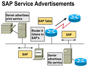 Routers do not forward SAP broadcasts. Instead, each router
builds its own SAP table and forwards the SAP table to other routers. By
default this occurs every 60 seconds but the router can use access lists to
control the SAPs accepted or forwarded.
 ![]()
1) SAP packets advertise
all NetWare network services 2) Can add excessive broadcast
traffic to the network By using the Service Advertisement
Protocol, or SAP, network resources such as file servers and print servers
can advertise their addresses and services they provide. Routers listen to
these SAPs, build a table of all known services,
and broadcast the table every sixty seconds. When a Novell client wants a
particular service, it sends a query. The router responds to this query
with a network address of the device providing the service. Now the client
can contact the device directly.

1.6.7. The GNS get nearest server protocol
The NetWare client/server interaction begins when the client powers up and runs its client startup programs. These programs use the client's network adapter on the LAN and initiate the connection sequence for the NetWare shell to use.
GNS is a broadcast that comes from a client using SAP. The nearest NetWare file server responds with a GNS reply. From that point on, the client can log in to the target server, make a connection, set the packet size, and proceed to use server resources.
If a NetWare server is located on the segment, it will respond to the client request. The Cisco router will not respond to the GNS request. If there are no NetWare servers on the local network, the Cisco router will respond with a server address from its own SAP table
1) GNS is a broadcast
from a client needing a server 2) Netware server and
Cisco router get this SAP packet 3) NetWare servers
provide GNS response

Novell IPX configuration tasks
Configuration of the router for IPX routing involves both global and interface parameters.

1.6.9. Verify IPX operation
Once IPX routing is configured, you can monitor and troubleshoot it using the commands shown in the figure
|
Monitoring command |
Displays |
|
Show ipx interface |
IPX status and parameters |
|
Show ipx route |
Routing table contents |
|
Show ipx servers |
IPX server list |
|
Show ipx traffic |
Number and type of packets |
|
Troubleshooting command |
Displays |
|
Debug ipx routing activity |
Information about RIP update packets |
|
Debug ipx sap |
Information about SAP update packets |
Chapter 2
Wan services
A WAN is a data communications network that operates beyond a LAN's geographic scope. A WAN is different from a LAN in other ways as well. To establish a WAN and use WAN carrier network services, one must subscribe to a Regional Bell operating company (RBOC) WAN service provider. A WAN uses data links such as Integrated Services Digital Network (ISDN) and Frame Relay. These are provided by carrier services to access bandwidth over wide-area geographies. A WAN provides connectivity between organizations, services, and remote users. WANs generally carry voice, data, and video.
WANs function at the three lowest
layers of the OSI reference model. They are the physical layer, the data link
layer, and the network layer. Figure ![]() illustrates
the relationship between the common WAN technologies and the OSI reference
model.
illustrates
the relationship between the common WAN technologies and the OSI reference
model.
Telephone and data services are the most commonly used WAN services. Telephone and data services are connected from the building's point of presence (POP) to the WAN provider's central office (CO). The CO is the local telephone company's central office to which all local loops in a given area connect and in which circuit switching of subscriber lines occurs.
An overview of the WAN cloud (see
Figure ![]() )
organizes WAN provider services into three main types:
)
organizes WAN provider services into three main types:


The LMI global addressing extension allows DLCIs to become unique network addresses for DTE devices. When one DTE sends a frame to another, it places the destination DLCI value in the frame header. The frame has been passed through the frame relay network. When it arrives at its destination, the frame relay network changes the DLCI field to reflect the address of the source, thus indicating to the destination device the origin of the frame.
2.1.2. CPE, demarc, "last mile", CP switch and toll network
WAN Service Providers
Advances in technology over the past decade have made a number of additional
WAN solutions available to network designers. When selecting an appropriate WAN
solution, you should discuss the costs and benefits of each with your service
providers.
When an organization subscribes to an
outside WAN service provider for network resources, the provider gives
connection requirements to the subscriber. For instance, the type of equipment
to be used to receive services. As shown in Figure ![]() ,
the following are the most commonly used terms associated with the main parts
of WAN services:
,
the following are the most commonly used terms associated with the main parts
of WAN services:
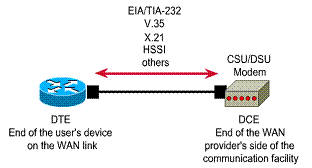
A key interface in the customer site
occurs between the data terminal equipment (DTE) and the data
circuit-terminating equipment (DCE). Typically, the DTE is the router. The DCE
is the device used to convert the user data from the DTE into a form acceptable
to the WAN service's facility. As shown in Figure ![]() ,
the DCE is either the attached modem, channel service unit/data service unit (CSU/DSU),
or terminal adapter/network termination 1 (TA/NT1).
,
the DCE is either the attached modem, channel service unit/data service unit (CSU/DSU),
or terminal adapter/network termination 1 (TA/NT1).
The WAN path between the DTEs is called the link, circuit, channel, or line. The DCE primarily provides an interface for the DTE into the communication link in the WAN cloud. The DTE/DCE interface acts as a boundary where responsibility for the traffic passes between the WAN subscriber and the WAN provider.
The DTE/DCE interface uses various protocols such as HSSI and V.35. These protocols establish the codes that the devices use to communicate with each other. Setup operation and user traffic paths are determined by this communication


Provider gives connection requirements to subscriber DTE/DCE-The point where responsibility passes
WAN virtual circuits
A virtual circuit is a logical circuit,
as opposed to a point-to-point circuit. It is created to ensure reliable
communication between two network devices. Two types of virtual circuits exist.
They are switched virtual circuits (SVCs) and
permanent virtual circuits (PVCs). ![]()
SVCs are virtual circuits that are dynamically established on demand and terminated when transmission is complete. Communication over an SVC consists of three phases. They are circuit establishment, data transfer, and circuit termination. The establishment phase involves creating the virtual circuit between the source and destination devices. Data transfer involves transmitting data between the devices over the virtual circuit. The circuit-termination phase involves tearing down the virtual circuit between the source and destination devices. SVCs are used in situations where data transmission between devices is sporadic. The circuit establishment and termination phases of SVCs represent a small bandwidth overhead, but this is usually much less than the overhead of making virtual circuits constantly available.
A PVC is a permanently established virtual circuit that consists of one mode called data transfer. PVCs are used in situations where data transfer between devices is constant. PVCs decrease the bandwidth use associated with the establishment and termination of virtual circuits, but increase costs due to constant virtual-circuit availability

2.1.4. WAN line types
WAN
links are available from the network providers at certain data rates, which
specifies the capacity of the link, measured in bits per second (bps). This
capacity determines how fast data can be moved across the WAN link. WAN
bandwidth is often provisioned in the
|
Line type |
Signal Standard |
Bit rate capacity |
|
DSO |
56 kbps |
|
|
DSo |
64 kbps |
|
|
T1 |
DS1 |
1.544 Mbps |
|
E1 |
ZM |
2.048 Mbps |
|
E3 |
M3 |
34.064 Mbps |
|
J1 |
Y1 |
2.048 Mbps |
|
T3 |
DS3 |
44.736 Mbps |
|
OC-1 |
SONET |
51.84 Mbps |
|
OC-3 |
SONET |
155.54 Mbps |
|
OC-9 |
SONET |
466.56 Mbps |
|
OC-12 |
SONET |
622.08 Mbps |
|
OC-18 |
SONET |
933.12 Mbps |
|
OC-24 |
SONET |
1244.16 Mbps |
|
OC-36 |
SONET |
1866.24 Mbps |
|
OC-48 |
SONET |
2477.32 Mbps |
2.2. WAN devices
Fundamental WAN devices
WANs use numerous types of devices, including the following:
The Figure shows the icons used for these WAN devices.

2.2.2. Routers and WAN switches
Routers are devices that implement the network service. They provide interfaces for a wide range of links and subnetworks at a wide range of speeds. Routers are active and intelligent network devices and thus can participate in managing the network. Routers manage networks by providing dynamic control over resources and supporting the tasks and goals for networks. These goals are connectivity, reliable performance, management control, and flexibility.
A WAN switch is a multiport networking device. It typically switches such traffic as Frame Relay, X.25, and Switched Multimegabit Data Service (SMDS). WAN switches typically operate at the data link layer of the OSI reference model. The Figure illustrates two routers at remote ends of a WAN that are connected by WAN switches. In this example the switches filter, forward, and flood frames based on the destination address of each frame
2.2.3. Describe modems on a WAN
A modem is a device that is used to connect between a digital network and a voice-grade telephone line. At the source, digital signals are converted to a form suitable for transmission over analog communication facilities. At the destination, these analog signals are returned to their digital form. The Figure illustrates a simple modem-to-modem connection through a WAN

2.2.4. CSU/DSUs on a WAN
A CSU/DSU is either a digital-interface device, or sometimes two separate digital devices. It adapts the physical interface on a DTE device (such as a terminal) to the interface of a DCE device (such as a switch) in a switched-carrier network. The Figure illustrates the placement of the CSU/DSU in a WAN implementation. Sometimes, CSUs/DSUs are integrated in the router box
Components Required: 1) Router port 2) CSU/DSU 3) Service provider
circuit

2.2.5. ISDN Terminal Adapters on a WAN
An ISDN Terminal Adapter (TA) is a device used to convert standard electrical signals into the form used by ISDN so that non-ISDN devices can connect to the ISDN network. For example, a TA would be used to connect a router serial port to a BRI capable device
2.3.1. Organizations that deal with WAN standards
WANs, like LANs, use the OSI reference model layered approach to encapsulation. However, WANs are mainly focused on the physical and data link layers. WAN standards typically describe both physical-layer delivery methods and data link-layer requirements, including addressing, flow control, and encapsulation. WAN standards are defined and managed by a number of recognized authorities, including the following agencies:
WAN physical layer standards
WAN physical layer protocols describe how to provide electrical, mechanical, operational, and functional connections for WAN services. Most WANs require an interconnection that is provided by a communications service provider (such as an RBOC), an alternative carrier (such as an Internet service provider), or a post, telephone, and telegraph (PTT) agency.
The WAN physical layer also describes the interface between the DTE and the DCE. Typically, the DCE is the service provider, and the DTE is the attached device, as shown in the Figure.
Several physical-layer standards define the rules governing the interface between the DTE and the DCE:
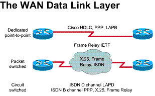
2.3.3. Name, and briefly describe, six WAN data link encapsulations
The WAN data link layer defines how
data is encapsulated for transmission to remote sites. WAN data-link protocols
describe how frames are carried between systems on a single data path. ![]() Figure
Figure
![]() shows
the common data-link encapsulations associated with WAN lines, which are:
shows
the common data-link encapsulations associated with WAN lines, which are:
1) HDLC - High-Level Data
Link Control 2) Frame Relay -
Simplified version of HDLC framing 3) PPP - Point-to-Point
Protocol 4) ISDN - Integrated
Service Digital Network (data-link signal)

Connection oriented
services involve three phases. In the connection establishment phase, a
single path between the source and destination device is determined.
Resources are typically reserved at this time to ensure consistent rate of
service. During the data transfer phase, data is transmitted sequentially
over the established path - arriving at the destination in the order on
which it was sent. The connection termination phase consists of terminating
the connection between source and destination when it is no longer needed.

2.4.1. Serial line frame fields
The two most common point-to-point WAN encapsulations are HDLC and PPP. All the serial line encapsulations share a common frame format, which has the following fields, as shown in the Figure:
Each WAN connection type uses a Layer 2 protocol to encapsulate traffic while it is crossing the WAN link. To ensure that the correct encapsulation protocol is used, configure the Layer 2 encapsulation type to use for each serial interface on a router. The choice of encapsulation protocol depends on the WAN technology and the communicating equipment. Encapsulation protocols that can be used with the WAN connection types covered in this chapter are PPP and HDLC
PPP
|
Flag |
Address |
Control |
Protocol |
Data |
FCS |
Flag |
HDLC
|
Flag |
Address |
Control |
Proprietary |
Data |
FCS |
Flag |
PPP
PPP is a standard serial-line encapsulation method (described in RFC 1332 and RFC 1661). This protocol can, among other things, check for link quality during connection establishment. In addition, there is support for authentication through Password Authentication Protocol (PAP) and Challenge Handshake Authentication Protocol (CHAP).
Technical overview: 1) Standard (RFC-based)
serial line encapsulation 2) Protocol type
specified 3) Link control protocol 4) Authentication

2.4.3. HDLC
HDLC is a data link layer protocol derived from the Synchronous Data Link Control (SDLC) encapsulation protocol. HDLC is Cisco's default encapsulation for serial lines. This implementation is very streamlined. There is no windowing or flow control, and only point-to-point connections are allowed. The address field is always set to all ones. Furthermore, a 2-byte proprietary type code is inserted after the control field. This means that HDLC framing is not interoperable with other vendors' equipment.
HDLC encapsulation is typically used when both ends of a dedicated-line connection are routers or access servers running the Cisco Internetwork Operating System (IOS) software. Because HDLC encapsulation methods may vary, PPP should be used with devices that are not running Cisco IOS software

Technical overview: 1) Default Cisco serial line encapsulation 2) Supports autoinstall 3) Proprietary (uses a 2-byte type code)
2.5. WAN Link options
2.5. 1. Two basic WAN link options
In general, as shown in the Figure, two types of WAN link options are available. These options are dedicated lines and switched connections. Switched connections, in turn, can be either circuit switched or packet switched. The following sections describe these types of link options
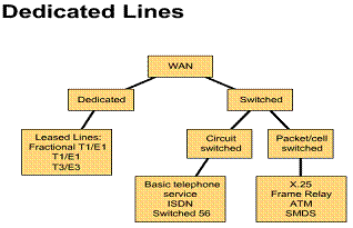
Dedicated lines
Dedicated lines, also called leased
lines, provide full-time service. ![]() Dedicated
lines are typically used to carry data, voice, and occasionally video. In data
network design, dedicated lines generally provide core or backbone connectivity
between major sites or campuses, as well as LAN-to-LAN connectivity. Dedicated
lines are generally considered reasonable design options for WANs.
Dedicated
lines are typically used to carry data, voice, and occasionally video. In data
network design, dedicated lines generally provide core or backbone connectivity
between major sites or campuses, as well as LAN-to-LAN connectivity. Dedicated
lines are generally considered reasonable design options for WANs.
When dedicated line connections are
made, a router port is required for each connection, along with a CSU/DSU and
the actual circuit from the service provider. ![]() The
cost of dedicated-line solutions can become significant when they are used to
connect many sites.
The
cost of dedicated-line solutions can become significant when they are used to
connect many sites.
Dedicated lines
Technology background:
1) Leased from WAN service provider, full-time service
2) Transmission speeds pf up to T3 (44.636 Mbps)
3) Most widely used is T! (1.544 Mbps)
4) Fractional T1 in increments of 64 kbps
Uses:
1) Often carry data and voice, occasionally video
2) Core WAN connectivity
3) LAN to WAN connectivity
Point-to-Point clarity is used for direct physical links
or for virtual links consisting of multiple physical links.
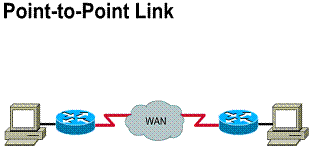
Leased lines
Dedicated, full-time connectivity is
provided by point-to-point serial links. ![]() Connections
are made using the router's synchronous serial ports with typical bandwidth use
of up to 2 Mbps (E1) available through the use of a CSU/DSU. Different
encapsulation methods at the data link layer provide flexibility and
reliability for user traffic. Dedicated lines of this type are ideal for
high-volume environments with a steady-rate traffic pattern. Use of available
bandwidth is a concern because you have to pay for the line to be available
even when the connection is idle.
Connections
are made using the router's synchronous serial ports with typical bandwidth use
of up to 2 Mbps (E1) available through the use of a CSU/DSU. Different
encapsulation methods at the data link layer provide flexibility and
reliability for user traffic. Dedicated lines of this type are ideal for
high-volume environments with a steady-rate traffic pattern. Use of available
bandwidth is a concern because you have to pay for the line to be available
even when the connection is idle.
Dedicated lines also are referred to as
point-to-point links. Their established path is permanent and fixed for each
remote network reached through the carrier facilities. A point-to-point link
provides a single, pre-established WAN communications path from the customer
premises through a carrier network, such as a telephone company, to a remote
network. The service provider reserves point-to-point links for the private use
of the customer. Figure ![]() illustrates
a typical point-to-point link through a WAN. Point-to-point is used for direct
physical links or for virtual links consisting of multiple physical links
illustrates
a typical point-to-point link through a WAN. Point-to-point is used for direct
physical links or for virtual links consisting of multiple physical links
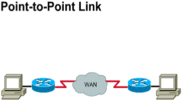

Components required:
1) Router port
2) CSU/DSU
3) Service provider circuit
2.5.4. Packet-switched connections
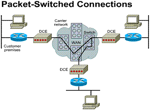
Packet switching is a WAN switching method in which network devices share a permanent virtual circuit (PVC) to transport packets from a source to a destination across a carrier network, as shown in the Figure. A PVC is similar to a point-to-point link. Frame Relay, SMDS, and X.25 are all examples of packet-switched WAN technologies.
Switched networks can carry variable-size frames (packets) or fixed-size cells. The most common packet-switched network type is Frame Relay
2.5.5. Frame Relay
Frame Relay was designed to be used over high-speed, high quality digital facilities.
As a result, Frame Relay does not offer
much error checking or reliability. Frame Relay expects upper-layer protocols
to attend to these issues. ![]()
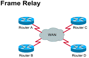
Frame Relay is a packet-switching data
communications technology. It can connect multiple network devices on a
multipoint WAN, as shown in Figure ![]() .
The design of Frame Relay WANs can affect certain aspects (such as split
horizon) of higher-layer protocols such as IP, IPX, and Apple-Talk. Frame Relay
is called a non-broadcast multi-access technology because it has no broadcast
channel. Broadcasts are transmitted through Frame Relay by sending packets to
all network destinations.
.
The design of Frame Relay WANs can affect certain aspects (such as split
horizon) of higher-layer protocols such as IP, IPX, and Apple-Talk. Frame Relay
is called a non-broadcast multi-access technology because it has no broadcast
channel. Broadcasts are transmitted through Frame Relay by sending packets to
all network destinations.
Frame Relay defines the connection between a customer DTE and a carrier DCE. The DTE is typically a router, and the DCE is a Frame Relay switch. (In this case, DTE and DCE refer to the data link layer, not the physical layer.) Frame Relay access is typically at 56 kbps, 64 kbps, or 1.544 Mbps.
Frame Relay is a cost-effective alternative to point-to-point WAN designs. A site can be connected to every other by a virtual circuit. Each router needs only one physical interface to the carrier. Frame Relay is implemented mostly as a carrier-provided service but can also be used for private networks. Frame Relay service is offered through a PVC. A PVC is an unreliable data link. A data-link connection identifier (DLCI) identifies a PVC. The DLCI number is a local identifier between the DTE and the DCE that identifies the logical circuit between the source and destination devices. The Service Level Agreement (SLA) specifies the committed information rate (CIR) provided by the carrier, which is the rate, in bits per second, at which the Frame Relay switch agrees to transfer data. (These topics are covered in depth in the "Frame Relay" chapter.)
Two common topologies can be used in a Frame Relay solution:
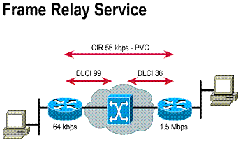
1) Data-link connection identifier (DLCI)
2) Committed information rate (CIR)
3) Access rate is 56 kbps, 64 kbps or 1.544 Mbps
2.5.6. Circuit-switched connections
Circuit switching is a WAN switching method in which a dedicated physical circuit is established, maintained, and terminated through a carrier network for each communication session. Used extensively in telephone company networks, circuit switching operates much like a normal telephone call. ISDN is an example of a circuit-switched WAN technology.
Circuit-switched connections from one site to another are brought up when needed and generally require low bandwidth. Basic telephone service connections generally operate no faster than 56 kbps, and Basic ISDN connections (BRI) provide lines at 64 or 128 kbps. Circuit-switched connections are used primarily to connect remote users and mobile users to corporate LANs. They are also used as backup lines for higher-speed circuits, such as Frame Relay and dedicated lines
Circuit-switched Connections
Technology background:
1) Connections on demand
2) Relatively low bandwidth
Uses:
1) Remote users
2) Mobile users
3) Backup lines
DDR
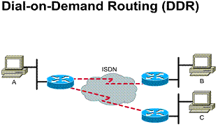
Dial-on-demand routing (DDR) is a technique in which a router can dynamically initiate and close circuit-switched sessions when transmitting end stations need them. When the router receives traffic destined for a remote network, a circuit is established, and the traffic is transmitted normally. The router maintains an idle timer that is reset only when interesting traffic is received. (Interesting traffic refers to traffic the router needs to route.) If the router receives no interesting traffic before the idle timer expires, however, the circuit is terminated. Likewise, if uninteresting traffic is received and no circuit exists, the router drops the traffic. When the router receives interesting traffic, it initiates a new circuit.
DDR allows a standard telephone
connection or an ISDN connection only when required by the volume of network
traffic. DDR may be less expensive than a dedicated-line or multipoint
solutions. DDR means that the connection is brought up only when a specific
type of traffic initiates the call or a backup link is needed. These
circuit-switched calls, indicated by the broken lines in Figure ![]() are
placed using ISDN networks. DDR is a substitute for dedicated lines when
full-time circuit availability is not required. In addition, DDR can be used to
replace point-to-point links and switched multi-access WAN services.
are
placed using ISDN networks. DDR is a substitute for dedicated lines when
full-time circuit availability is not required. In addition, DDR can be used to
replace point-to-point links and switched multi-access WAN services.
DDR can be used to provide backup load sharing and interface backup. For example, several serial lines may exist, but the second serial line would only be used when the first line is very busy so that load sharing can occur. When WAN lines are used for critical applications, a DDR line might be configured for use in case the primary lines go down. In this case the secondary line enables itself so traffic can still get across.
Compared to LAN or campus-based networking, the traffic that uses DDR is typically low volume and sporadic. DDR initiates a WAN call to a remote site only when there is traffic to transmit.
When configuring for DDR, enter
configuration commands that indicate what protocol packets make-up interesting
traffic to initiate the call. To do this, access control list statements are
entered to identify the source and destination addresses, and specific protocol
selection criteria for initiating the call are chosen. Then the interfaces
where the DDR call initiates must be established. This step designates a dialer
group. The dialer group associates the results of the access control list
specification of interesting packets to the router's interfaces for dialing a
WAN call. ![]()
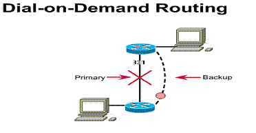
Dial Backup is a service that activates a backup serial line. This backup line
can be used as a backup link when the primary link fails, or as a source of
additional bandwidth when the traffic load on the primary link reaches a
threshold
2.5.8. Describe ISDN
Telephone companies developed ISDN with the intention of creating a totally digital network. ISDN devices include the following:
As shown in Figure ![]() ,
ISDN interface reference points include the following:
,
ISDN interface reference points include the following:
There are two ISDN services, Basic Rate Interface (BRI) and Primary Rate Interface (PRI). ISDN BRI operates mostly over the copper twisted-pair telephone wiring in place today. ISDN BRI delivers a total bandwidth of a 144 kbps line into three separate channels. Two of the channels, called B (bearer) channels, operate at 64 kbps and are used to carry voice or data traffic. The third channel, the D (delta) channel, is a 16-kbps signaling channel used to carry instructions that tell the telephone network how to handle each of the B channels. ISDN BRI often is referred to as 2B+D.
ISDN provides great flexibility to the
network designer because of its capability to use each of the B channels for
separate voice or data applications. For example, one ISDN 64-kbps B channel
can download a long document from the corporate network while the other B
channel browses a Web page. When designing a WAN, you should be careful to
select equipment that has the right feature to take advantage of ISDN
flexibility. ![]()
Three channels: 1) Two 64 kbps bearear (B) channels 2) One 16 kbps signaling
(D) channel
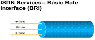
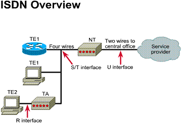
Chapter 3
Overview
The number of software applications that are built around the Internet Protocol (IP) and the Web are growing rapidly. Consequently, today's network administrators must manage complex wide area networks (WANs). These WANs place a great demand on network resources, and require high-performance networking technologies. WANs are complex environments that incorporate multiple media, multiple protocols, and inter-connection to other networks, such as the Internet. Growth and manageability of these network environments are achieved by the often complex interaction of protocols and features.
Despite improvements in equipment performance and media capabilities, WAN design is becoming more difficult. Carefully designed WANs can reduce problems associated with a growing networking environment. To design reliable, scalable WANs, network designers must keep in mind that each WAN has specific design requirements. This chapter provides an overview of the methodologies utilized to design WANs
WAN Communication
3.1.1. WAN design requirements
WAN communication occurs between geographically separated areas. When a local end station wants to communicate with a remote end station (an end station located at a different site), information must be sent over one or more WAN links. Routers within WANs are connection points of a network. These routers determine the most appropriate path through the network for the required data streams.
WAN communication is often called a service because the network provider (often the telephone company) charges users for the WAN services it provides. Circuit-switching and packet-switching technologies are two types of WAN services, each of which has advantages and disadvantages. For example, circuit-switched networks offer users dedicated bandwidth that cannot be infringed upon by other users, but network resources may be under-utilized during periods of low traffic. In contrast, packet switching allows carrier network resources to be shared by many users since each packet contains addressing information that allows it to be switched through the best available path. Packet-switched networks offer more flexibility and used network bandwidth more efficiently than circuit-switched networks, but if the network becomes overloaded, packets may be delayed or discarded.
Traditionally, relatively low throughput, high delay, and high error rates have characterized WAN communication. WAN connections are also characterized by the cost of renting media (wire) from a service provider to connect two or more campuses together. The WAN infrastructure is often rented from a service provider. Therefore, WAN network designs must minimize the cost of bandwidth and optimize bandwidth efficiency. For example, all technologies and features used in WANs are developed to meet the following design requirements:
Traditional shared-media networks are being overtaxed because of the following new network requirements:
The new WAN infrastructures must be more complex. They are based on new technologies, and able to handle an ever-increasing (and rapidly changing) application mix with required and guaranteed service levels. The projected 300% traffic increase over the next five years will encourage enterprises' attempts to further contain WAN costs.
WAN connections generally handle important information and are optimized for price and performance. The routers connecting the campuses, for example, generally apply traffic optimization, multiple paths for redundancy, dial backup for disaster recovery, and quality of service (QoS) for critical applications. The table summarizes the various WAN technologies that support such WAN requirements
|
WAN Technology |
Typical uses |
|
Leased line |
Leased lines can be used for Point-to-Point Protocols (PPP) networks and hub-and-spoke topologies, or backup of another type of link. |
|
Integrated Services Digital Network (ISDN) |
ISDN can be used for cost-effective remote access to corporate networks. It provides support for voice and video as well as a backup for another type of link. |
|
Frame Relay |
Frame Relay provides a cost-effective, high-speed, low-latency mesh topology between remote sites. It can be used in both private and carrier-provided networks. |
3.1.2. LAN/WAN integration issues
Distributed applications need increasingly more bandwidth. The explosion of Internet use is problematic for many existing LAN architectures. Voice communications have increased significantly, due to more dependency on centralized voice mail systems for verbal communications. The network is the critical tool for information flow. Networks must cost less while supporting emerging applications and larger number of users. Performance must also increase.
Until fairly recently, local- and wide-area communications have remained logically separate. Bandwidth is essentially free in the LAN, and connectivity is limited only by hardware and implementation costs. Bandwidth is the overriding cost in the WAN.
Internet applications such as voice and real-time video require predictable, high-level LAN and WAN performance. These multimedia applications are quickly becoming an essential part of the business productivity toolkit. Companies are beginning to consider implementing new intranet-based, bandwidth-intensive multimedia applications. These include video training, videoconferencing, and voice-over IP. The impact of these applications on the existing networking infrastructure will become a serious concern.
Suppose a company has relied on its corporate network for business-traffic and wants to integrate a video-training application. The network must be able to provide guaranteed QoS (quality of service). This QoS must deliver the multimedia traffic, but not allow it to interfere with the business-critical traffic. Consequently, network designers need greater flexibility in solving multiple internetworking problems without creating multiple networks or writing off existing data communication investments
3.2.1. WAN design goals
Designing a WAN can be a challenging task. The discussions that follow outline several areas that should be carefully considered when planning a WAN implementation. The steps described here can lead to lower WAN cost and improved performance. Businesses can continually improve their WANs by incorporating these steps into the planning process.
Two primary goals drive WAN design and implementation:
WAN design generally needs to take into account the following three factors:
Characterizing network traffic is critical to successful WAN planning. Few planners perform this key step well, if at all.
The overall goal of WAN design has two parts. Costs must be minimized based on the three general factors mentioned, while delivering service that does not compromise established availability requirements. The two primary concerns are availability and cost. These issues are essentially at odds. Any increase in availability must generally be reflected as an increase in cost. Therefore, you must carefully weigh the relative importance of resource availability and overall cost.
The first step in the design process is to understand the business requirements. WAN requirements must reflect the goals, characteristics, business processes, and policies of the business in which they operate.
3.2.2. The gathering requirements phase of WAN design
The first step in designing a WAN is to gather data about the business structure and processes. Next, determine who the most important people will be in helping to design the network. Speak to major users and find out their geographic location, their current applications, and their projected needs. The final network design should reflect the user requirements.
In general, users primarily want application availability in their networks. The chief components of application availability are response time, throughput, and reliability.
User requirements can be assessed in a number of ways. The more involved the users are in the process, the more likely the evaluation will be accurate. In general, the following methods can be used to obtain this information:
After gathering data about the corporate structure, determine where information flows in the company. Find out where shared data resides and who uses it. Determine whether data outside the company is accessed.
Make sure performance issues of any existing network are understood. If time permits, analyze the performance of the existing network.
3.2.3. Analyzing requirements
Network requirements need to be analyzed, including the customer's business and technical goals. What new applications will be implemented? Are any applications Internet based? What new networks will be accessed? How will you know if the new design is successful?
Availability measures the usefulness of the network. Many things affect availability, including throughput, response time, and access to resources. Every customer has a different definition of availability. Availability can be increased by adding more resources. Resources, however, drive up cost. Network design seeks to provide the greatest availability for the least cost.
The objective of analyzing requirements is to determine the average and peak data rates for each source over time. Define the activities of a normal work day. Include in the definition the type of traffic passed, level of traffic, response time of hosts, and the time to execute file transfers. Observe network equipment use over the test period.
If the tested network's characteristics are close to those of the new network, the new network's requirements can be estimated based on the projected number of users, applications, and topology. This is a best-guess approach to traffic estimation given the lack of tools to measure detailed traffic behavior.
In addition to passively monitoring an existing network, measure the activity and traffic generated by a known number of users attached to a representative test network. Use the results to predict activity and traffic for the anticipated population.
One problem with defining workloads on networks is that it is difficult to accurately pinpoint traffic load and network device performance as functions of the number of users, type of application, and geographic location. This is especially true without a real network in place.
Consider the following factors that influence the dynamics of the network:
Each traffic source has its own metric, and each must be converted to bits per second. You should standardize traffic measurements to obtain per user traffic requirements in bits per second. Finally, a factor should be applied to account for protocol overhead, packet fragmentation, traffic growth, and safety margin. What-if analyses can be conducted by varying this factor. For example, Microsoft Office could be run from a server, and then traffic volume generated from users sharing the application on the network could be analyzed. This volume will help to determine the bandwidth and server requirements to install Microsoft Office on the network
Analyze Requirements
1) Business Requirements
2) Technical Requirements
3) New applications or business operations
4) Performance Requirements
5) Availability Requirements
3.2.4. WAN sensitivity testing
Sensitivity testing involves breaking stable links and observing what happens. When working with a test network, this is relatively easy. The network can be disturbed by removing an active interface, and monitoring how the change is handled by the network. One can then tell how traffic is rerouted, the speed of convergence, whether any connectivity is lost, and whether problems arise in handling specific types of traffic. The level of traffic on a network can also be changed to determine the effects on the network when traffic levels approach media saturation.
3.3. How to Identify and Select Networking Capabilities
3.3.1. The use of the OSI model in WAN design
After understanding the networking requirements, it is time to identify and design the computing environment to meet these requirements. The following sections will help with these tasks.
Hierarchical models for network design allow for designing networks in layers. To understand the importance of layering, consider the OSI model, a layered model for understanding computer communications. By using layers, the OSI reference model simplifies the tasks required for two computers to communicate. Hierarchical models for network design also use layers to simplify the tasks required for internetworking. Each layer can be focused on specific functions, thereby allowing the networking designer to choose the right systems and features for the layer.
Using a hierarchical design can facilitate changes. Modularity in network design allows the creation of design elements that can be replicated as the network grows. Also, because networks will require upgrades, the cost and complexity of making the upgrade are constrained to a small subset of the overall network. In large flat or meshed network architectures, changes tend to affect a large number of systems. Identification of failure-points in a network can be facilitated by structuring the network into small, easy-to-understand elements. Network managers can easily understand the transition points in the network, which helps identify failure points
A hierarchical WAN design model
Network designs tend to follow one of two general design strategies. They are either mesh or hierarchical. In a mesh structure, the network topology is flat. All routers perform essentially the same functions, and there is usually no clear definition of where specific functions are performed. Expansion of the network tends to proceed in a haphazard, arbitrary manner. In a hierarchical structure the network is organized in layers, each of which has one or more specific functions.
Benefits to using a hierarchical model include the following:
Benefits of a hierarchical design model
1) Scalability
2) Ease of implementation
3) Ease of troubleshooting
4) Predictability
5) Protocol support
6) Manageability
Three hierarchical WAN design layers
A hierarchical network design includes the following three layers:
The Figure shows a high-level view of the various aspects of a hierarchical network design
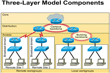
3.3.4. Describe the three-layer design model components
A layer is identified as a point in the network where an OSI reference model Layer 3 (network layer) boundary occurs. Layer 3 devices or other devices that separate the network into broadcast domains bind the three layers. As shown in the figure, the three-layer model consists of core, distribution, and access layers. Each of these have specific functions:
A three-layer model can meet the needs of most enterprise networks. However, not all environments require a full three-layer hierarchy. In some cases a two-layer design or even a single layer flat network may be adequate. Even in these cases, however, a hierarchical structure should be planned or maintained to allow these network designs to expand to three layers as the need arises. The following sections discuss in more detail the functions of the three layers. Then, a discussion of one- and two-layer hierarchies will take place
3.3.5. Core-layer functions
The core layer's function is to provide a fast and reliable path between remote sites, as shown in the figure. This layer of the network does not perform any packet manipulation or filtering. The core layer is usually implemented as a WAN. The WAN needs redundant paths so that the network can withstand individual circuit outages and continue to function. Load sharing and rapid convergence of routing protocols are also important design features. Efficient use of bandwidth in the core is always a concern
1) Redundant paths 2) Load sharing 3) Rapid convergence 4) Efficient use of
bandwidth
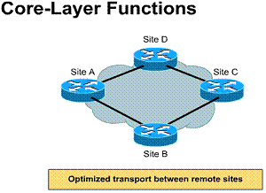
3.3.6. Distribution-layer functions
The distribution layer of the network is the demarcation point between the access and core layers and helps to define and differentiate the core. The purpose of this layer is to provide boundary definition. It is the layer at which packet manipulation occurs. In the WAN environment, the distribution layer can include several functions, such as the following:
The distribution layer would include the campus backbone with all its connecting routers, as shown in the figure. Because policy is typically implemented at this level, we can say that the distribution layer provides policy based connectivity. Policy-based connectivity means that the routers are programmed to allow only acceptable traffic on the campus backbone. Note that good network design practice would not put end stations on the backbone. Not putting end stations on the backbone frees up the backbone to act strictly as a transit path for traffic between workgroups or campus-wide servers.
In non-campus environments, the distribution layer can be the point at which remote sites access the corporate network
1) Control access to
services 2) Define path metrics 3) Control network
advertisements

3.3.7. Access-layer functions
The access layer is the point at which local end users are allowed into the network, as shown in the figure. This layer can also use access control lists or filters to further optimize the needs of a particular set of users. In the campus environment, access-layer functions can include the following:
The access layer connects users into LANs, and in turn, LANs to backbones or WAN links. This approach enables designers to distribute services of devices operating at this layer. The access layer allows logical segmentation of the network and grouping of users based on their function. Traditionally, this segmentation is based on organizational boundaries (such as Marketing, Administration, or Engineering). However, from a network management and control perspective, the main function of the access layer is to isolate broadcast traffic to the individual workgroup or LANs. In non-campus environments, the access layer can give remote sites access to the corporate network via some wide-area technology, such as Frame Relay, ISDN, or leased lines. These technologies will be covered in the following chapters
1) Provide logical
segmentation 2) Group users with
common interests 3) Isolate broadcast
traffic from the workgroup
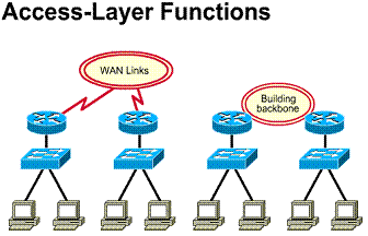
3.3.8. One-layer network designs
Not all networks require a three-layer hierarchy. A key design decision becomes the placement of servers. They can be distributed across multiple LANs or concentrated in a central server farm location. The figure shows a distributed server design. A one-layer design is typically implemented if there are only a few remote locations in the company, and access to applications is mainly done via the local LAN to the site file server. Each site is its own broadcast domain
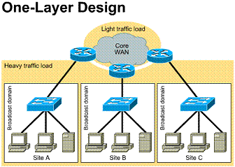
3.3.9. Two-layer network designs
In a two-layer design a WAN link is used to interconnect separate sites, as shown in the figure. Inside the site multiple LANs may be implemented, with each LAN segment being its own broadcast domain. In the figure, the router at Site F becomes a concentration point from WAN links.
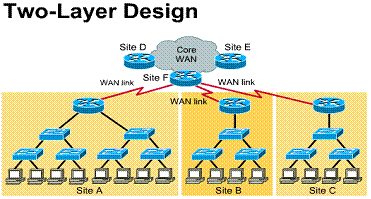
3.3.10. The benefits of hierarchical WAN designs
A hierarchical WAN design places Layer
3 routing points throughout the network. Routing points provide a method for
controlling data traffic patterns. Routers have the ability to determine paths
from the source host to destination hosts based on Layer 3 addressing.
Therefore, data traffic flows up the hierarchy only as far as it needs to find
the destination host, as shown in Figure ![]() .
.
If Host A were to establish a
connection to Host B, the traffic from this connection would travel to Router 1
and be forwarded back down to Host B. Notice in Figure ![]() that
this connection does not require that any traffic be placed on the link between
Router 1 and Router 2, thus conserving the bandwidth on that link.
that
this connection does not require that any traffic be placed on the link between
Router 1 and Router 2, thus conserving the bandwidth on that link.
In a two-layer WAN hierarchy, shown in
Figure ![]() ,
the traffic only travels up the hierarchy as far as needed to get to the
destination, thus conserving bandwidth on other WAN links.
,
the traffic only travels up the hierarchy as far as needed to get to the
destination, thus conserving bandwidth on other WAN links.
Notice that the layer classifications are determined by the number of routers in the path between the hosts and the WAN access
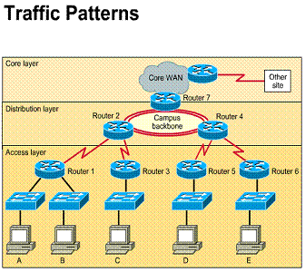
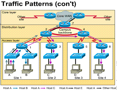
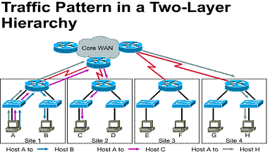
3.3.11. Server placement in WANs
The placement of servers relating to
host access affects traffic patterns. If you place an enterprise server in the
access layer of Site 1, as shown in Figure ![]() ,
all traffic destined for that server from other sites is forced to go across
links between Routers 1 and 2. This consumes major quantities of bandwidth from
Site 1.
,
all traffic destined for that server from other sites is forced to go across
links between Routers 1 and 2. This consumes major quantities of bandwidth from
Site 1.
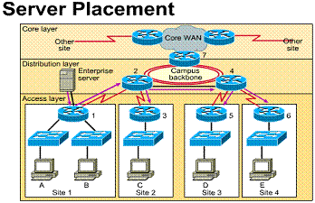 If the enterprise server is placed at a higher layer in the
hierarchy, as shown in Figure
 ![]() ,
the traffic on the link between Routers 1 and 2 is reduced and is available for
users at Site 1 to access other services. In Figure
,
the traffic on the link between Routers 1 and 2 is reduced and is available for
users at Site 1 to access other services. In Figure ![]() ,
a workgroup server is placed at the access layer of the site where the largest
concentration of users is located, and traffic crossing the WAN link to access
this server is limited. Thus, more bandwidth is available to access resources
outside the site
,
a workgroup server is placed at the access layer of the site where the largest
concentration of users is located, and traffic crossing the WAN link to access
this server is limited. Thus, more bandwidth is available to access resources
outside the site
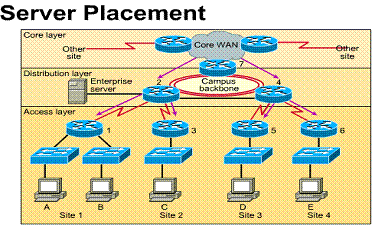 Unnecessary
traffic consumes bandwidth Moving
servers to correct locations frees up WAN bandwidth
1) Placement of servers
based on users 2)
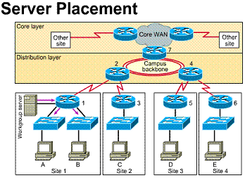
3.3.12. Alternatives to dedicated WAN links
It is not uncommon for remote sites to access the WAN core layer by using WAN technologies other than dedicated links. As shown in the figure, Frame Relay and ISDN are two such alternatives. If a remote site is small and has low demand for access to services in the corporate network, ISDN would be a logical choice for this implementation. Perhaps another remote site is too distant for a leased line to be affordable. Frame Relay would be an appropriate choice because distance is not a factor in its pricing
Different WAN technologies can be used to access WAN
core
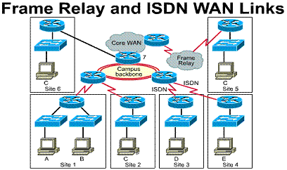
Chapter 4
Overview
The previous chapter covered wide-area network (WAN) technologies. It is important to understand that WAN connections are controlled by protocols that perform the same basic functions as Layer 2 LAN protocols, such as Ethernet. In a LAN environment, in order to move data between any two nodes or routers, a data path must be established, and flow control procedures must be in place to ensure delivery of data. This is also true in the WAN environment and is accomplished by using WAN protocols such as Point-to-Point Protocol.
In this chapter, you will learn about the basic components, processes, and operations that define Point-to-Point Protocol (PPP) communication. In addition, this chapter discusses the use of Link Control Protocol (LCP) and Network Control Program (NCP) frames in PPP. Finally, you will learn how to configure and verify the configuration of PPP. Along with PPP authentication, you will learn to use Password Authentication Protocol (PAP) and Challenge Handshake Authentication Protocol (CHAP).
4.1. PPP
4.1.1. The need of PPP
In the late 1980s, Serial Line Internet Protocol (SLIP) was limiting the Internet's growth. PPP was created to solve remote Internet connectivity problems. Additionally, PPP was needed to be able to dynamically assign IP addresses and allow for use of multiple protocols. PPP provides router-to-router and host-to-network connections over both synchronous and asynchronous circuits.
PPP is the most widely used and most popular WAN protocol because it offers all the following features:
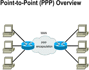
PPP components
PPP addresses the problems of Internet connectivity by employing three main components:
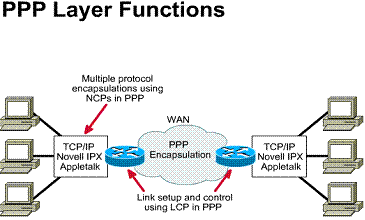
PPP layer functions
PPP uses a layered architecture, as shown in the Figure. With its lower-level functions, PPP can use:
With its higher-level functions, PPP supports or encapsulates several network-layer protocols with NCPs. These higher-layer protocols include the following:
These are functional fields containing standardized codes to indicate the network-layer protocol type that PPP encapsulates
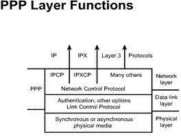
The six fields of a PPP frame
As shown in the Figure, the fields of a PPP frame are as follows:
Field length, in bytes:
|
Variable |
2 or 4 |
||||
|
Flag |
Address |
Control |
Protocol |
Data |
FCS |
The four phases through which PPP establishes a point-to-point connection
PPP provides a method of establishing, configuring, maintaining, and terminating a point-to-point connection. In order to establish communications over a point-to-point link, PPP goes through four distinct phases:
There are three classes of LCP frames:
LCP frames are used to accomplish the work of each of the four LCP phases listed above.
PPP session
establishment/termination 1) Link establishment
phase 2) Link quality phase 3) Network-layer protocol
phase 4) Link termination phase
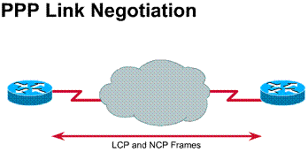
4.2.2. Phase 1: link establishment and configuration negotiation
In the link establishment and configuration negotiation phase, each PPP device sends LCP packets to configure and establish the data link. LCP packets contain a configuration option field that allows devices to negotiate the use of options. Examples of these options include the maximum transmission unit (MTU), the compression of certain PPP fields, and the link authentication protocol. If a configuration option is not included in an LCP packet, the default value for that configuration option is assumed.
Before any network-layer datagrams (for example, IP) can be exchanged, LCP must first open the connection and negotiate the configuration parameters. This phase is complete when a configuration acknowledgment frame has been sent and received
4.2.3. Phase 2: link-quality determination
LCP allows an optional link-quality determination phase following the link establishment and configuration negotiation phase. In the link-quality determination phase, the link is tested to determine whether the link quality is good enough to bring up network-layer protocols.
In addition, after the link has been established and the authentication protocol chosen, the client or user workstation can be authenticated. Authentication, if used, takes place before the network-layer protocol configuration phase begins. LCP can delay transmission of network-layer protocol information until this phase is completed.
PPP supports two authentication protocols: Password Authentication Protocol (PAP) and Challenge Handshake Authentication Protocol (CHAP). Both of these protocols are detailed in RFC 1334, "PPP Authentication Protocols." These protocols are covered later in this chapter, in the section "PPP Authentication."
Phase 3: network-layer protocol configuration negotiation
When LCP finishes the link-quality determination phase, network-layer protocols can be separately configured by the appropriate NCP and can be brought up and taken down at any time.
In this phase, the PPP devices send NCP packets to choose and configure one or more network-layer protocols (such as IP). When each of the chosen network-layer protocols has been configured, datagrams from each network-layer protocol can be sent over the link. If LCP closes the link, it informs the network-layer protocols so that they can take appropriate action. When PPP is configured, you can check its LCP and NCP states by using the show interfaces command
Describe phase 4: link termination
LCP can terminate the link at any time. This is usually done at the request of a user. However, it can happen because of a physical
event, such as the loss of a carrier or a timeout
4.3.1. PAP
The authentication phase of a PPP session is optional. After the link has been established and the authentication protocol chosen, the peer can be authenticated. If it is used, authentication takes place before the network-layer protocol configuration phase begins.
The authentication options require that the calling side of the link enter authentication information. This will help to ensure that the user has the network administrator's permission to make the call. Peer routers exchange authentication messages.
When configuring PPP authentication, you can select Password Authentication Protocol (PAP) or Challenge Handshake Authentication Protocol (CHAP). In general, CHAP is the preferred protocol.
As shown in the Figure, PAP provides a simple method for a remote node to establish its identity using a two-way handshake. First, the PPP link establishment phase is completed. Then a username/password pair is repeatedly sent by the remote node across the link until authentication is acknowledged or the connection is terminated.
PAP is not a strong authentication protocol. Passwords are sent across the link in clear text. There is also no protection from playback or repeated trial-and-error attacks. The remote node is in control of the frequency and timing of the login attempts
1) Passwords sent in
clear text 2) Peer in control of
attempts
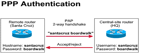
CHAP
CHAP is used to periodically verify the identity of the remote node, using a three-way handshake, as shown in the Figure. This is done upon initial link establishment and can be repeated any time after the link has been established. CHAP offers features such as periodic verification to improve security. This makes CHAP more effective than PAP. PAP verifies only once, which makes it vulnerable to hacks and modem playback. Further, PAP allows the caller to attempt authentication at will, without first receiving a challenge. This makes PAP vulnerable to brute-force attacks, however CHAP does not allow a caller to attempt authentication without a challenge.
After the PPP link establishment phase is complete, the host sends a challenge message to the remote node. The remote node responds with a value. The host checks the response against its own value. If the values match, the authentication is acknowledged. Otherwise, the connection is terminated.
CHAP provides protection against playback attacks through the use of a variable challenge value that is unique and unpredictable. The use of repeated challenges is intended to limit the time of exposure to any single attack. The local router (or a third-party authentication server, such as Netscape Commerce Server) is in control of the frequency and timing of the challenges
Use secret known only to authenticator and peer
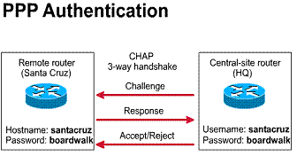
4.3.3. Writing the IOS command steps to configure PPP authentication
To configure PPP authentication, do the following:
|
Step 1 |
On each router define the username and password to expect from the remote router: Router(config)#username name password secret The arguments are described as follows: Name- This is the host name of the remote router. (It is case sensitive) Secret- On Cisco routers, the secret password must be the same for both routers. |
|
Step 2 |
Enter interface configuration mode for the desired interface |
|
Step 3 |
Configure the interface for PPP encapsulation: Router(config-if)#encapsulation ppp |
|
Step 4 |
Configure PPP authentication: Router(config-if)#ppp authentication |
|
Step 5 |
If Chap and PAP are enabled, then the first method specified is requested during the link negotiation phase. If the peer suggests using the second method or simply refuses the first method then the second method is tried. |
|
Step 6 |
In CISCO Release 11.1 or later, if you choose PAP and are configuring the router that will send the PAP information (in other words, the router responding to a PAP request), you must enable PAP on the interface. PAP is disabled by default; to enable PAP, use the following command: Router(config-if)#ppp pap sent-username username password password |
4.3.4. Writing the IOS command to configure CHAP authentication
The following methods can be used to simplify CHAP configuration tasks on the router:
Router(config-if)# ppp chap hostname
Router(config-if)#ppp chap password
This password is not used when the router authenticates a remote device
Chapter 5
Overview
Many types of WAN technologies can be implemented to solve connectivity issues for users who need network access from remote locations. This chapter will cover the services, standards, components, operation, and configuration of Integrated Services Digital Network (ISDN) communication. ISDN is specifically designed to solve the low bandwidth problems that small offices or dial-in users have with traditional telephone dial-in services.
Telephone companies developed ISDN with the intention of creating a totally digital network. ISDN was developed to use the existing telephone wiring system, and it works very much like a telephone. When a call is made with ISDN, the WAN link is brought up for the duration of the call and is taken down when the call is completed. It is very similar to calling a friend on the phone and then hang up when through talking.
5.1. ISDN
5.1.1. What is ISDN ?
ISDN allows digital signals to be
transmitted over existing telephone wiring. This became possible when the
telephone company switches were upgraded to handle digital signals. ISDN is
generally viewed as an alternative to leased lines. Leased lines can be used
for telecommuting and networking small and remote offices into LANs. ![]()
Telephone companies developed ISDN as
part of an effort to standardize subscriber services. This included the
User-Network Interface (UNI), which is how the screen looks when the user dials
into the network, and network capabilities. Standardizing subscriber services ensures
international compatibility. The ISDN standards define the hardware and call
setup schemes for end-to-end digital connectivity. Hardware and call setup
schemes help achieve the goal of worldwide connectivity by ensuring that ISDN
networks easily communicate with one another. Basically, the digitizing
function is done at the user site rather than the telephone company. ![]()
The ability of ISDN to bring digital connectivity to local sites has many benefits:
In the design phase it should be ensured that the equipment selected has the feature set that takes advantage of the flexibility of ISDN. In addition, the following ISDN design issues must be kept in mind:
What is ISDN? ISDN is a set of
standards that defines an end-to-end digital network. Benefits are: 1) Carries many types of
network traffic (for example data, voice, video) 2) Sets up calls faster
than basic telephone service 3) Faster data transfer
rate than modems
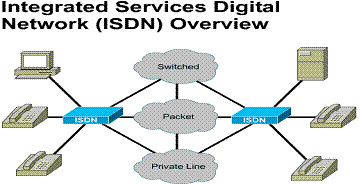
ISDN basic components
ISDN components include terminals,
terminal adapters (TAs), network-termination (NT) devices, line-termination
equipment, and exchange-termination equipment. The table provides a summary of
the ISDN components. ![]() ISDN
terminals come in two types, Type 1 or Type 2, as shown in Figure
ISDN
terminals come in two types, Type 1 or Type 2, as shown in Figure ![]() .
Specialized ISDN terminals are referred to as Terminal Equipment type 1 (TE1).
Non-ISDN terminals such as Data Terminal Equipment (DTE) that predate the ISDN
standards are referred to as Terminal Equipment type 2 (TE2). TE1s connect to
the ISDN network through a four-wire, twisted-pair digital link. TE2s connect
to the ISDN network through a TA. The ISDN TA can be either a standalone device
or a device included inside the TE2. If the TE2 is implemented as a standalone
device, it connects to the TA via a standard physical-layer interface.
.
Specialized ISDN terminals are referred to as Terminal Equipment type 1 (TE1).
Non-ISDN terminals such as Data Terminal Equipment (DTE) that predate the ISDN
standards are referred to as Terminal Equipment type 2 (TE2). TE1s connect to
the ISDN network through a four-wire, twisted-pair digital link. TE2s connect
to the ISDN network through a TA. The ISDN TA can be either a standalone device
or a device included inside the TE2. If the TE2 is implemented as a standalone
device, it connects to the TA via a standard physical-layer interface.
Beyond the TE1 and TE2 devices, the
next connection point in the ISDN network is the Network Termination type 1
(NT1) device, or the Network Termination type 2 (NT2) device. These are
network-termination devices that connect the four-wire subscriber wiring to the
conventional two-wire local loop. In
|
Component |
Description |
|
Terminal equipment type 1 (TE1) |
Designates a device that is compatible with the ISDN network. A TE1 connects to a network termination of either type 1 or type 2. |
|
Terminal equipment type 2 (TE2) |
Designates a device that is not compatible with ISDN and requires a terminal adapter. |
|
Terminal adapter (TA) |
Converts standard electrical signals into the form used by ISDN so that non-ISDN devices can connect to the ISDN network. |
|
Network termination type 1 (NT1) |
Connects four-wire ISDN subscriber wiring to the conventional two-wire local loop facility. |
|
Network termination type 1 (NT2) |
Directs traffic to and from different subscriber devices and the NT1. The NT2 is an intelligent device that performs switching and concentrating. |
End-to-end digital network for data, fax, voice and
video.
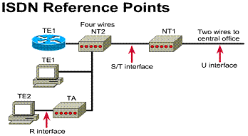
5.1.3. ISDN reference points
Customer Premise Equipment (CPE) covers a wide variety of capabilities and requires a variety of services and interfaces. Therefore, the standards refer to interconnects by reference points rather than specific hardware requirements. Reference points are a series of specifications that define the connection between specific devices, depending on their function in the end-to-end connection. It is important to know about these interface types because a CPE device, such as a router, may support different reference types. The reference points supported will determine what specific equipment is required for purchase.
The table in Figure ![]() provides
a summary of the reference points that affect the customer side of the ISDN
connection.
provides
a summary of the reference points that affect the customer side of the ISDN
connection. ![]() A
sample ISDN configuration is shown in Figure
A
sample ISDN configuration is shown in Figure ![]() ,
where three devices are attached to an ISDN switch at the Central Office (CO).
Two of these devices are ISDN compatible, so they can be attached through an S
reference point to NT2 devices. The third device (a standard, non-ISDN
telephone) attaches through the R reference point to a TA. Although they are
not shown, similar user stations are attached to the far-right ISDN switch.
,
where three devices are attached to an ISDN switch at the Central Office (CO).
Two of these devices are ISDN compatible, so they can be attached through an S
reference point to NT2 devices. The third device (a standard, non-ISDN
telephone) attaches through the R reference point to a TA. Although they are
not shown, similar user stations are attached to the far-right ISDN switch.
|
Reference Point |
Description |
|
R |
References the connection between a non-ISDN-compatible device and a TA |
|
S |
References the points that connect into the NT2 or customer switching device, It is the interface that enables calls between the various parts of the CPE. |
|
T |
Electrically identical to the S interface, a T interface references the outbound connection form the NT2 to the ISDN network or NT1 |
|
U |
References the connection between the
NT1 and the ISDN network owned by the phone company. The U reference point is
relevant only in |
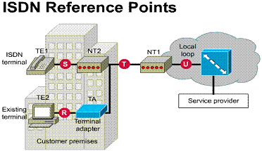
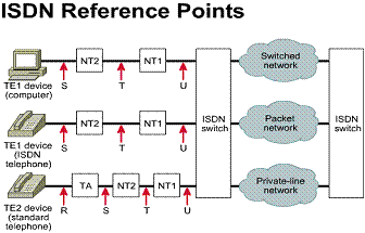
Functions refer to devices or
hardware functions.
5.1.4. ISDN switches and SPIDs
For proper ISDN operation, it is
important that the correct switch type is configured on the ISDN device. The
most common type in the
In addition to learning about the switch type your service provider uses, you also need to know what Service Profile Identifiers (SPIDs) are assigned to your connection. The ISDN carrier provides a SPID to identify the line configuration of the ISDN service. SPIDs are a series of characters (that can look like phone numbers) that identify you to the switch at the CO. After you are identified, the switch links the services you ordered to the connection.
Differentiate between E, I, and Q ISDN protocols
Work on standards for ISDN began in the late 1960s. A comprehensive set of ISDN recommendations was published in 1984. These are continuously updated by the Consultative Committee for International Telegraph and Telephone (CCITT), now the International Telecommunication Union Telecommunication Standardization Sector (ITU-T). ITU-T groups and organizes the ISDN protocols as described in the table.
Q.921 recommends the data link process on the ISDN D Channel. Q.931 governs the network layer functionality between the terminal endpoint and the local ISDN switch. This protocol does not impose an end-to-end recommendation. The various ISDN providers and switch types can and do use various implementations of Q.931. Other switches were developed before the standards groups finalized this standard.
Because switch types are not standard, when configuring the router, you need to specify the ISDN to which you are connecting. In addition, Cisco routers have debug commands to monitor Q.931 and Q.921 processes when an ISDN call is initiated or being terminated.
|
Protocols that begin with this letter |
Are used for these purposes |
|
E |
These protocols recommend telephone network standards for ISDN. For example, the E.164 protocol describes international addressing for ISDN, |
|
I |
These protocols deal with concepts, terminology, and general ISDN concepts and the structure of other I-series recommendations; the I.200 series deals with service aspects of ISDN; the I.300 series describes network aspects; the I.400 series describes how the UNI is provided. |
|
Q |
These protocols cover how switching and signaling should operate. The term signaling in this context means the process of call setup used. Q.921 describes the ISDN data-link processes of Link Access Procedure on the D channel (LAPD), which functions like Layer 2 processes in the Open System Interconnection (OSI) reference model. Q.391 specifies OSI reference model Layer 3 functions. |
5.2.1. The ITU-T standards of the first three layers of ISDN
ISDN utilizes a suite of ITU-T standards spanning the physical, data link, and network layers of the OSI reference model:
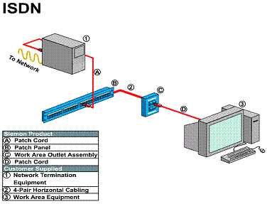
5.2.2. The ISDN physical layer
ISDN physical layer (Layer 1) frame formats differ depending on whether the frame is outbound (from terminal to network-the TE frame format) or inbound (from network to terminal-the NT frame format). Both of the frames are 48 bits long, of which 36 bits represent data. Actually, the frames are two 24 bit frames in succession consisting of two 8-bit B channels, a 2-bit D channel, and 6 bits of framing information (2*(2*8B+2D+6F) = 32B+4D+12F = 36BD+12F = 48BDF). Both physical-layer frame formats are shown in the figure. The bits of an ISDN physical-layer frame are used as follows:
Note that there are 8000 ISDN BRI frames sent per second. There are 24 bits in each frame (2*8B+2D+6F = 24) for a bit rate of 8000*24 = 192Kbps. The effective rate is 8000*(2*8B+2D) = 8000*18 = 144Kbps.
Multiple ISDN user devices can be physically attached to one circuit. In this configuration, collisions can result if two terminals transmit simultaneously. ISDN therefore provides features to determine link contention. These features are part of the ISDN D channel, which is described in more detail later in this chapter.
A= activation bit B1=B1 channel bits B2=B2 channel bits D=D channel (4 bitsx4000
frames/sec =16 kbps) bit E=Echo of previous bit F=Framing bit L= Loading balance bit S= Spare bit
Field
length in bits:
|
F |
L |
B1 |
L |
D |
L |
F |
L |
B2 |
L |
D |
L |
B1 |
L |
D |
L |
B2 |
NT frame (network to terminal, inbound)
Field length, in bits:
|
F |
L |
B1 |
E |
D |
A |
F |
F |
B2 |
E |
D |
S |
B1 |
E |
D |
S |
B2 |
TE frame (terminal to network, outbound)
5.2.3. The ISDN data link layer
Layer 2 of the ISDN signaling protocol is Link Access Procedure on the D channel (LAPD). LAPD is similar to High-Level Data Link Control (HDLC) and Link Access Procedure, Balanced (LAPB). LAPD is used across the D channel to ensure that control and signaling information flows and is received properly.
The LAPD flag and control fields are identical to those of HDLC. The LAPD address field can be either one or two bytes long. If the extended address bit of the first byte is set, the address is one byte. If it is not set, the address is two bytes. The first address field byte contains the Service Access Point Identifier (SAPI), which identifies the portal at which LAPD services are provided to Layer 3. The Command/ Response (C/R) bit indicates whether the frame contains a command or a response. The Terminal Endpoint identifier (TEI) field identifies either a single terminal or multiple terminals. All 1s in the TEI field indicates a broadcast
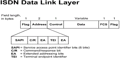
5.2.4. The ISDN network layer
Two Layer 3 specifications are used for ISDN signaling: ITU-T I.450 (also known as ITU-T Q.930) and ITU-T I.451 (also known as ITU-T Q.931). Together, these protocols support user-to-user, circuit-switched, and packet-switched connections. A variety of call establishment, call termination, information and miscellaneous messages are specified. These include setup, connect, release, user information, cancel, status and disconnect. The figure shows the typical stages of an ISDN circuit-switched call


5.2.5. ISDN encapsulation
When deploying remote access solutions, several encapsulation choices are available. The two most common encapsulations are PPP and HDLC. ISDN defaults to HDLC. However, PPP is much more robust than HDLC. It provides an excellent mechanism for authentication and negotiation of compatible link and protocol configuration. One of the other encapsulations for end-to-end ISDN is LAPB (Link Access Procedure Balanced).
ISDN interfaces allow only a single Layer 2 encapsulation type for connection. Once an ISDN call has been established, the router can use this connection to carry any of the network-layer protocols required.
Most networking designs use PPP encapsulation. PPP is a powerful and modular peer-to-peer mechanism used to establish data links, provide security, and encapsulate data traffic. Once a PPP connection is negotiated between two devices, it can then be used by network protocols such as IP and IPX to establish network connectivity.
PPP is an open standard specified by RFC 1661. PPP was designed with several features that make it particularly useful in remote access applications. PPP uses Link Control Protocol (LCP) to initially establish the link and agree on configuration. There are built-in security features in the protocol. Password Authentication Protocol (PAP) and Challenge Handshake Authentication Protocol (CHAP) make robust security design easier. CHAP is a popular authentication protocol for call screening.
PPP consists of several components:
PPP authentication is enabled with the ppp authentication interface command. PAP and CHAP can be used to authenticate the remote connection. CHAP is considered a superior authentication protocol because it uses a three-way handshake to avoid sending the password in clear text on the PPP link
Three uses for ISDN
ISDN has many uses in networking. The following sections discuss the following ISDN uses:
Remote access involves connecting users located at remote locations through dialup connections. The remote location can be a telecommuter's home, a mobile user's hotel room, or a small remote office. The dialup connection can be made via an analog connection using basic telephone service or via ISDN. Connectivity is affected by speed, cost, distance, and availability.
Remote access links generally represent the lowest-speed link in the enterprise. Any improvements in speed are desirable. The cost of remote access tends to be relatively low, especially for basic telephone service. ISDN service fees can vary widely, and they often depend on the geographic area, service availability, and billing method. Dialup services, including ISDN, may have distance limitations particular to individual service providers
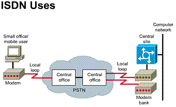
5.3.2. ISDN remote nodes
With the remote nodes method, as shown
in Figure ![]() ,
the users connect to the local LAN at the central site through the Public
Switched Telephone Network (PSTN) for the duration of the call. Aside from
having a lower-speed connection, the remote user sees the same environment the
local user sees. The connection to the LAN is typically through an access
server. This device usually combines the functions of a modem and those of a
router. When the remote user is logged in, he or she can access servers at the
local LAN as if they were local.
,
the users connect to the local LAN at the central site through the Public
Switched Telephone Network (PSTN) for the duration of the call. Aside from
having a lower-speed connection, the remote user sees the same environment the
local user sees. The connection to the LAN is typically through an access
server. This device usually combines the functions of a modem and those of a
router. When the remote user is logged in, he or she can access servers at the
local LAN as if they were local.
This method offers many advantages. It is the most secure and flexible, and it is the most scalable. Only one PC is required for the remote user, and many client software solutions are available. The only additional hardware required at the remote location is a modem. The main disadvantage of this method is the additional administrative overhead required to support the remote user. Because of its many advantages, this solution is used in the remainder of the design examples in this chapter.
The full-time telecommuter/teleworker is one who normally works out of the home. This
user is usually a power user who needs access to the enterprise networks for
large amounts of time. This connection should be reliable and available at all
times. Such a requirement would generally point to ISDN as the connection
method, as shown in Figure ![]() .
With this solution, the ISDN connection can be used to service any phone needs,
as well as to connect the workstation
.
With this solution, the ISDN connection can be used to service any phone needs,
as well as to connect the workstation
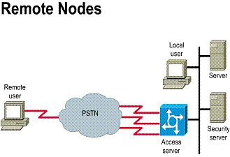
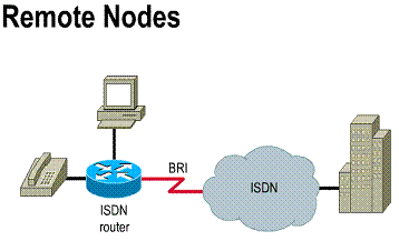
Remote user appears to be a network
node 1) Components
-ISDN router
-Remote client software
2) Single user
5.3.3. ISDN SOHO connectivity
A Small Office or Home Office (SOHO)
consisting of a few users requires a connection that provides faster, more
reliable connectivity than an analog dialup connection. In the configuration
shown in the figure, all the users at the remote location have equal access to
services located at the corporate office through an ISDN router. This offers to
the casual or full-time
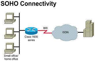
1) Components and
considerations -ISDN router -Multiple remote users at the same location
5.4.1. ISDN
BRI and ISDN PRI
There are two ISDN services: BRI and PRI. The ISDN BRI service offers two 8-bit B channels and one 2-bit D channel, often referred to as 2B+D, as shown in the Figure. ISDN BRI delivers a total bandwidth of a 144-kbps line into three separate channels (8000 frames per second * (2*8-bit B channel+2 bit D channel)=8000*18 = 144kbps). BRI B channel service operates at 64 kbps (8000 frames per second* 8-bit B channel) and is meant to carry user data and voice traffic.
ISDN provides great flexibility to the network designer because of its ability to use each of the B channels for separate voice and/or data applications. For example, a long document can be downloaded from the corporate network over one ISDN 64-kbps B channel while the other B channel is being used to connect to browse a Web page.
The third channel, the D channel, is a 16-kbps (8000 frames per second * 2 bit D channel) signaling channel used to carry instructions that tell the telephone network how to handle each of the B channels. BRI D channel service operates at 16 kbps and is meant to carry control and signaling information, although it can support user data transmission under certain circumstances. The D channel signaling protocol occurs at Layers 1 through 3 of the OSI reference model.
Terminals cannot transmit into the D channel unless they first detect a specific number of ones (indicating no signal) corresponding to a preestablished priority. If the TE detects a bit in the echo (E) channel that is different from its D bits, it must stop transmitting immediately. This simple technique ensures that only one terminal can transmit its D message at one time. This technique is similar and has the same effect as collision detection in Ethernet LANs. After successful D message transmission, the terminal has its priority reduced by requiring it to detect more continuous ones before transmitting. Terminals cannot raise their priority until all other devices on the same line have had an opportunity to send a D message. Telephone connections have higher priority than all other services, and signaling information has a higher priority than nonsignaling information.
ISDN PRI service offers 23 8-bit channels and one 8-bit D channel plus one framing bit in North America and Japan, yielding a total bit rate of 1.544 Mbps (8000 frames per second * (23 * 8-bit B channels + 8-bit D channel + 1 bit framing) = 8000*8*24.125 = 1.544 Mbps) (the PRI D channel runs at 64 kbps). ISDN PRI in Europe, Australia, and other parts of the world provides 30 8-bit B channels plus one 8-bit D channel plus one 8-bit Framing channel, for a total interface rate of 2.048 Mbps (8000 frames per second* (30*8-bit B channels + 8-bit D channel + 8-bit Framing channel = 8000*8*32 =2.048 Mbps).
In the T1/E1 and higher data rate frames the B channels are strung together like boxcars in a freight train. Like boxcars in a switchyard the B channels are rearranged and moved to other frames as they traverse the Public Switched Telephone Network (PTSN) until they reach their destination. This path through the switch matrix establishes a synchronous link between the two endpoints. This allows continuous voice communications without pauses, dropped data, or degradation. ISDN takes advantage of this digital transmission structure for the transfer of digital data

5.4.2. How BRI connectivity is established
Based on application need and traffic engineering, BRI or PRI services are selected for ISDN connectivity from each site. Traffic engineering may require multiple BRI services or multiple PRIs at some sites. Once connected to the ISDN fabric by BRI or PRI interfaces, design of ISDN end-to-end services must be implemented.
The BRI local loop is terminated at the customer premise at an NT1. The interface of the local loop at the NT1 is called the U reference point. On the customer premise side of the NT1 is the S/T reference point. The figure shows a typical BRI installation.
Two common types of ISDN Customer Premise Equipment (CPE) are available for BRI services: LAN routers and PC TAs. Some BRI devices offer integrated NT1s and integrated TAs for analog telephones.
ISDN LAN routers provide routing
between ISDN BRI and the LAN by using dial-on-demand routing (DDR). DDR
automatically establishes and releases circuit-switched calls, providing
transparent connectivity to remote sites based on networking traffic. DDR also
controls establishment and release of secondary B channels based on load
thresholds. Multilink PPP is used to provide bandwidth aggregation when using
multiple B channels. Some ISDN applications may require the
PC TAs connect to PC workstations either by the PC bus or externally through the communications ports (such as RS-232) and can be used similarly to analog (such as V.34) internal and external modems.
PC TAs can provide a single PC user with direct control over ISDN session initiation and release, similar to using an analog modem. Automated mechanisms must be provided to support the addition and removal of the secondary B channel. Cisco 200 Series PC cards can provide ISDN services to a PC

5.5.1. ISDN global and interface parameter configuration tasks
You must specify global and interface parameters to prepare the router for operation in an ISDN environment.
Global parameter tasks include the following:
Interface parameter tasks include the following:
Global Configuration -Select switch type,
specify traffic to tigger DDR call Interface Configuration -Select interface
specifications, Configure ISDN addressing Optional Feature Configuration
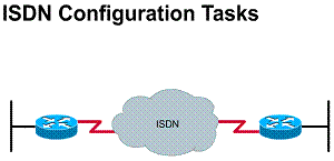
5.5.2. Write the IOS commands to configure ISDN BRI
To configure BRI and enter interface configuration mode, use the interface bri command in global configuration mode. The full syntax of the command is:
interface bri
The number argument describes the port, connector, or interface card number. The numbers are assigned at the factory at the time of installation or when added to a system, and can be displayed by using the show interfaces command.
The example output shown in the Figure configures BRI 0 to call and receive calls from two sites, uses PPP encapsulation on outgoing calls, and uses CHAP authentication on incoming calls
Output
interface bri 0
encapsulation ppp
no keepalaive
dialer map ip 131.108.36.10 name EB1 234
dialer map ip 131.108.36.9 name EB2 456
dialer-group 1
isdn spid1 0146334600
isdn spid2 0146334610
isdn T200 1000
ppp authentification chap
5.5.3. Writing the IOS commands to define an ISDN switch type
Before using ISDN BRI, you must define
the ISDN switch-type global command to
specify the CO switch to which the router connects. The Cisco IOS command
output shown in the Figure helps illustrate the supported BRI switch types (in
isdn switch-type
The argument indicates the service provider switch type. The switch-type defaults to none, which disables the switch on the ISDN interface. To disable the switch on the ISDN interface, specify isdn switch-type none
The following example configures the AT&T 5ESS switch type:
isdn switch-type basic-5ess
Output
kdt-3640(config)#isdn switch-type ?
basic-1tr6
1tr6 switch type for
basic-5ess
AT&T 5ESS switch type for the
basic-dms100
basic-net3
NET3 switch type for the
basic-ni1 National ISDN-1 switch type
basic-nwnet3
NET3 switch type for
basic-nznet3
NET3 switch type for
basic-ts013
TS013 switch type for
ntt NTT
switch type for
vn2
VN2
switch type for
vn3
VN3
and VN4 switch types for
5.5.4. Write the IOS commands pertaining to SPIDs
SPIDs allow multiple ISDN devices, such as voice and data devices, to share the local loop. In many cases, such as when you are configuring the router to connect to a DMS-100, you need to input the SPIDs.
Remember that ISDN is typically used for dialup connectivity. The SPIDs are processed during each call setup operation. You use the isdn spid2 command in interface configuration mode to define at the router the SPID number that has been assigned by the ISDN service provider for the B2 channel. The full syntax of the command is isdn spid2 spid- [ldn]. The optional LDN command is for a local dial directory number. On most switches, the number must match the called party information coming in from the ISDN switch in order to use both B channels.
You use the no isdn spid2 command to disable the specified SPID, thereby preventing access to the switch. If you include the LDN (Local Directory Number) in the no form of this command, the access to the switch is permitted, but the other B channel might not be able to receive incoming calls. The full syntax of the command is:
no isdn spid2 [spid-number] [ldn]
The [spid-number] argument indicates the number identifying the service to which you have subscribed. This value is assigned by the ISDN service provider and is usually a 10-digit telephone number with some extra digits. By default, no SPID number is defined
Router(config-if)#isdn spid1 spid-number [ldn]
-Sets a B channel Service Profile Identifier (SPID) required by many service providers
Router(config-if)#isdn spid2 spid-number [ldn]
-Sets a SPID for the second B channel
5.5.5. Write the IOS commands for a complete ISDN BRI configuration
This section is based on the output
shown in Figure ![]() ,
which shows a BRI configuration.
,
which shows a BRI configuration.
The table in Figure ![]() describes
the commands and parameters shown in the example.
describes
the commands and parameters shown in the example.
The table in Figure ![]() describes
the dialer map parameters shown in the example.
describes
the dialer map parameters shown in the example.
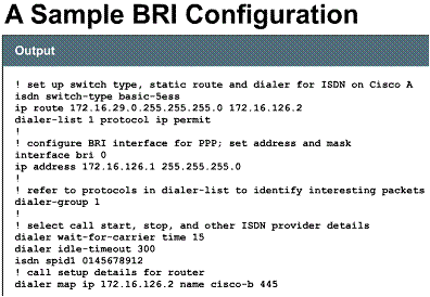
|
Command/Parameter |
Description |
|
isdn switch-type |
Selects AT&T switch as the CO ISDN switch type for this router |
|
Dialer-list 1 protocol ip permit |
Associates permitted IP traffic with the dialer group 1. The router will not start an ISDN call for any other packet traffic with dialer group 1. |
|
Interface bri 0 |
Selects an interface with TA and other ISDN functions on the router. |
|
Dialer-group 1 |
Associates the BRI 0 interface with dialing access group 1. |
|
Dialer wait-for-carrier-time |
Specifies a 15-second maximum time to the provider to respond after the call initiates |
|
Dialer idle-timeout |
The number of seconds of idle time before the router drops the ISDN call. Note that a long duration is configured to delay termination. |
|
dialer map parameter |
Description |
|
IP |
Name of protocol |
|
Destination address |
|
|
Name |
An identification for the remote side router. Refers to the called router. |
|
ISDN connection number used to reach this DDR destination. |
5.5.6. Describe how to confirm BRI operations
To confirm BRI operations, use the show isdn status command to inspect the status of your BRI interfaces. In the example output the TEIs have been successfully negotiated and ISDN Layer 3 (end-to-end) is ready to make or receive calls
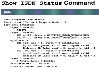
5.6.1. DDR considerations
When building networking applications, you must determine how ISDN connections will be initiated, established, and maintained. DDR creates connectivity between ISDN sites by establishing and releasing circuit-switched connections as needed by networking traffic. DDR can provide network routing and directory services in numerous ways to provide the illusion of full-time connectivity over circuit-switched connections.
To provide total control over initial DDR connections, you must carefully consider the following issues:
5.6.2. Writing IOS commands pertaining to verifying DDR operation
The commands shown in the table can be used to verify that DDR is operating:
|
Command |
Description |
|
Ping/telnet |
When you ping or telnet a remote site or when interesting traffic triggers a link, the router sends a change in link status message to the console. |
|
Show dialer |
Used to obtain general diagnostic information about an interface configured for DDR, such as the number of times the dialer string has been successfully reached, and the idle timer and the fast idle timer values for each B channel. Current call-specific information is also provided, such as the length of the call and the number and name of the device to which the interface us currently connected. |
|
Show isdn active |
Use this command when using ISDN, It shows that a call is in progress and lists the numbered call. |
|
Show isdn status |
Used to show the statistics if the ISDN connection |
|
Show ip route |
Displays the routes known to the router, including static and dynamically learned routes. |
5.6.3. Write IOS commands pertaining to troubleshooting DDR operation
The commands shown in Figure ![]() can
be used to troubleshoot DDR operation. You troubleshoot SPID problems by using
the debug isdn q921 command. In example
output,
can
be used to troubleshoot DDR operation. You troubleshoot SPID problems by using
the debug isdn q921 command. In example
output, ![]() you
can see that isdn
spid1
was rejected by the ISDN switch. You check the status of the Cisco 700 ISDN
line with the show
status
command, as shown in Figure
you
can see that isdn
spid1
was rejected by the ISDN switch. You check the status of the Cisco 700 ISDN
line with the show
status
command, as shown in Figure ![]()
Troubleshooting DDR Operation
|
Command |
Description |
|
Debug isdn q921 |
Verifies that you have a connection to the ISDN switch |
|
Debug dialer |
Shows such information as what number the interface is dialing |
|
Clear interface |
Used to clear a call that is in progress. In a troubleshooting situation, it is sometimes useful to clear historical statistics to track the current number of successful calls relative to failures. Use this command with care. It sometimes requires that you clear both the local and remote routers. |
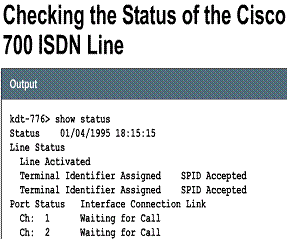
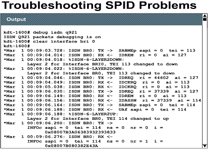
![]()
Chapter 6 - Frame Relay
Overview
You have learned that PPP and ISDN are two types of WAN technologies that can be implemented to solve connectivity issues between geographically distant locations. In this chapter, you will learn about another type of WAN technology, Frame Relay, which can be implemented to solve connectivity issues for users who need access to geographically distant locations.
You will learn about Frame Relay services, standards, components, and operation. In addition, this chapter describes the configuration tasks for Frame Relay service, along with the commands for monitoring and maintaining a Frame Relay connection
6.1. Frame Relay technology
6.1.1. What is Frame Relay ?
Frame Relay is a standard for both the Consultative Committee for International Telegraph and Telephone (CCITT) and American National Standards Institute (ANSI) that defines a process for sending data over a public data network (PDN). It is a high performance, efficient data technology used in networks throughout the world. Frame Relay is a way of sending information over a WAN by dividing data into packets. Each packet travels through a series of switches in a Frame Relay network to reach its destination. It operates at the physical and data link layers of the OSI reference model, but it relies on upper-layer protocols such as TCP for error correction. Frame Relay was originally conceived as a protocol for use over ISDN interfaces. Today, Frame Relay is an industry standard, switched data link layer protocol that handles multiple virtual circuits using High-Level Data Link Control (HDLC) encapsulation between connected devices. Frame Relay uses virtual circuits to make connections through a connection-oriented service.
The network providing the Frame Relay
interface can be either a carrier-provided public network or a network of
privately owned equipment, serving a single enterprise. A Frame Relay network
consists of two types of devices, user and network. User devices include
computers, servers, etc. Frame Relay network devices include switches, routers,
CSU/DSUs, or multiplexers. As you have learned, user
devices are often referred to as data terminal equipment (DTE), whereas network
equipment that interfaces to DTE is often referred to as data
circuit-terminating equipment (DCE), as shown in Figure ![]()
![]() .
.
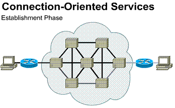
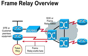
Connection oriented services involve three
phases. In the connection establishment phase, a single path between the source
and destination devices is determined. Resources are typically reserved at this
time to ensure consistent rate of service. During the data transfer phase, data
is transmitted sequentially over the established path - arriving at the destination
in the order in which it was sent, The connection termination phase consists of
terminating the connection between source and destination when it is no longer
needed.
6.1.2. Frame Relay terminology
Following are some terms that are used in this chapter to discuss Frame Relay:
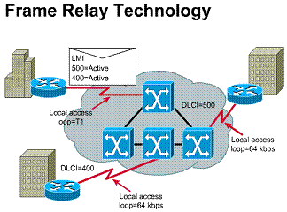
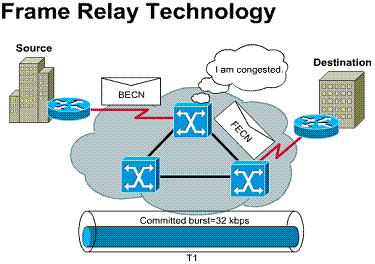
6.1.3. Frame Relay operation
Frame Relay can be used as an interface to either a publicly available carrier-provided service or to a network of privately owned equipment. You deploy a public Frame Relay service by putting Frame Relay switching equipment in the central office of a telecommunications carrier. Frame Relay service lowers user cost from traffic-sensitive charging rates. Also, users do not have to spend the time and effort to administer and maintain the network equipment and service.
No standards for interconnecting equipment inside a Frame Relay network currently exist. Therefore, the support of Frame Relay interfaces does not necessarily dictate that the Frame Relay protocol is used between the network devices. Thus, traditional circuit switching, packet switching, or a hybrid approach combining these technologies can be used, as shown in the Figure.
The lines that connect user devices to the network equipment can operate at a speed selected from a broad range of data rates. Speeds between 56 kbps and 2 Mbps are typical, although Frame Relay can support lower and higher speeds.
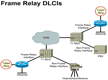
6.1.4. Frame Relay DLCIs
Frame Relay provides a means for
multiplexing many logical data conversations, referred to as virtual circuits,
through a shared physical medium. This is accomplished by assigning DLCIs to
each DTE/DCE pair of devices.![]()
Frame Relay multiplexing provides more flexible and efficient use of available bandwidth. Therefore, Frame Relay allows users to share bandwidth at a reduced cost. For example, say you have a WAN using Frame Relay, and the Frame Relay is equivalent to a group of roads. The phone company usually owns and maintains the roads. You can choose to rent out a road (or path) exclusively for your company (dedicated), or you can pay less to rent a path on shared roads. Of course, Frame Relay could also be run entirely over private networks. However, it's rarely used in this manner.
Frame Relay standards address permanent
virtual circuits (PVCs) that are administratively
configured and managed in a Frame Relay network. Frame Relay PVCs are identified by DLCIs, as shown in Figure ![]() ,
Frame Relay DLCIs have local significance. That is, the values themselves are
not unique in the Frame Relay WAN. Two DTE devices connected by a virtual
circuit might use a different DLCI value to refer to the same connection.
,
Frame Relay DLCIs have local significance. That is, the values themselves are
not unique in the Frame Relay WAN. Two DTE devices connected by a virtual
circuit might use a different DLCI value to refer to the same connection.
Frame Relay provides a means for multiplexing many logical data conversations. The service provider's switching equipment constructs a table mapping DLCI values to outbound ports. When a frame is received, the switching device analyzes the connection identifier and delivers the frame to the associated outbound port. The complete path to the destination is established before the first frame is sent
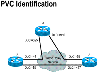
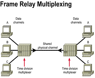
6.1.5. The fields of the Frame Relay frame format
The Frame Relay frame format is shown in the Figure. The flag fields indicate the beginning and end of the frame. Following the leading flag field are two bytes of address information. Ten bits of these two bytes make up the actual circuit ID (that is, the DLCI).
The following are the Frame Relay frame fields:
Field length, in bytes
1 2 Variable 2 1
|
Flag |
Address, including DLCI, FECN, BECN and DE bits |
Data |
FCS |
Flag |
6.1.6. Frame Relay addressing
DLCI
address space is limited to ten bits. This creates a possible 1024 DLCI
addresses. The usable portion of these addresses is determined by the LMI type
used. The Cisco LMI type supports a range of DLCI addresses from DLCI 16-1007
for carrying user data. The ANSI/ITU LMI type supports the range of addresses
from DLCI 16-992 for carrying user data. The remaining DLCI addresses are
reserved for vendor implementation. This includes LMI messages and multicast
addresses. In the Figure, assume two PVCs, one
between
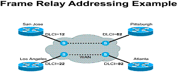
6.2. LMI: Cisco's Implementation of Frame Relay
6.2.1. LMI operation
There was a major development in Frame Relay history in 1990. Cisco Systems, StrataCom, Northern Telecom, and Digital Equipment Corporation formed a group to focus on Frame Relay technology development and accelerate the introduction of interoperable Frame Relay products. This group developed a specification conforming to the basic Frame Relay protocol. They also extended it by including features that provide additional capabilities for complex internetworking environments. These Frame Relay extensions are referred to as LMI (local management interface).
Listed here are the main functions of the LMI process:
Three LMI types can be invoked by the router: ansi, cisco, and q933a.
LMI extensions
In addition to the basic Frame Relay protocol functions for transferring data, the Frame Relay specification includes LMI extensions that make supporting large, complex internetworks easier. Some LMI extensions are referred to as common and everyone who adopts the specification is expected to implement them. Other LMI functions are referred to as optional. A summary of the LMI extensions follows:
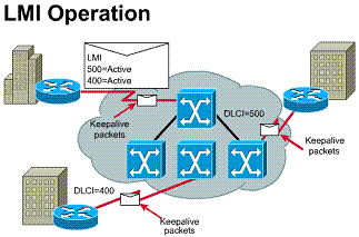
6.2.2. The fields of the LMI frame format
The Frame Relay specification also includes the LMI procedures. LMI messages are sent in frames distinguished by an LMI-specific DLCI (defined in the consortium specification as DLCI = 1023). The LMI frame format is shown in the Figure.
After the flag and LMI DLCI fields, the LMI frame contains four mandatory bytes. The first of the mandatory bytes (unnumbered information indicator) has the same format as the LAPB unnumbered information (UI) frame indicator, with the poll/final bit set to zero. The next byte is referred to as the protocol discriminator, which is set to a value that indicates LMI. The third mandatory byte (call reference) is always filled with zeros.
The final mandatory byte is the message type field. Two message types have been defined. They are status messages and status-enquiry messages. Status messages respond to status-enquiry messages. Examples of these messages are (1) keepalives (messages sent through a connection to ensure that both sides will continue to regard the connection as active) and (2) a status message of an individual report on each DLCI defined for the link. These common LMI features are expected to be a part of every implementation that conforms to the Frame Relay specification.
Together, status and status-enquiry messages help verify the integrity of logical and physical links. This information is critical in a routing environment because routing protocols make decisions based on link integrity.
Next is an information element (IE) field of a variable number of bytes. Following the message type field is some number of IEs. Each IE consists of a one-byte IE identifier, an IE length field, and one or more bytes containing actual data
LMI Frame Format
1 2 1 Variable 2 1
|
Flag |
LMI DLCI |
Unnumbered information indicator |
Protocol discriminator |
Call Reference |
Message Type |
Information element(s) |
FCS |
Flag |
6.3. LMI Features
6.3.1. Global addressing
In addition to the common LMI features, several optional LMI extensions are extremely useful in an internetworking environment. The first important optional LMI extension is global addressing. With this extension, the values inserted in the DLCI field of a frame are globally significant addresses of individual end-user devices (for example, routers).
As noted earlier, the basic (nonextended) Frame Relay specification supports only values of the DLCI field that identify PVCs with local significance. In this case, there are no addresses that identify network interfaces, or nodes attached to these interfaces. Because these addresses do not exist, they cannot be discovered by traditional address resolution and discovery techniques. This means that with normal Frame Relay addressing, static maps must be created. These static maps tell routers which DLCIs to use to find a remote device and its associated internetwork address.
In the Figure, note that each interface
has its own identifier. Suppose that
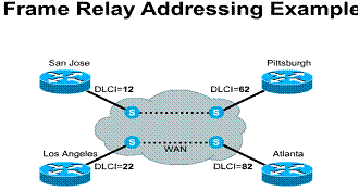
6.3.2. Multicasting and inverse ARP
Multicasting is another valuable optional LMI feature. Multicast groups are designated by a series of four reserved DLCI values (1019 to 1022). Frames sent by a device using one of these reserved DLCIs are replicated by the network and sent to all exit points in the designated set. The multicasting extension also defines LMI messages that notify user devices of the addition, deletion, and presence of multicast groups. In networks that take advantage of dynamic routing, routing information must be exchanged among many routers. Routing messages can be sent efficiently by using frames with a multicast DLCI. This allows messages to be sent to specific groups of routers.
The Inverse ARP mechanism allows the router to automatically build the Frame Relay map, as shown in the Figure. The router learns the DLCIs that are in use from the switch during the initial LMI exchange. The router then sends an Inverse ARP request to each DLCI for each protocol configured on the interface if the protocol is supported. The return information from the Inverse ARP is then used to build the Frame Relay map
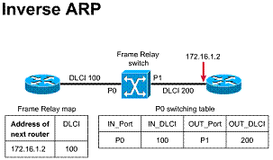
6.3.3. Frame Relay mapping
The router next-hop address determined from the routing table must be resolved to a Frame Relay DLCI, as shown in the Figure. The resolution is done through a data structure called a Frame Relay map. The routing table is then used to supply the next-hop protocol address or the DLCI for outgoing traffic. This data structure can be statically configured in the router, or the Inverse ARP feature can be used for automatic setup of the map.

6.3.4. Frame Relay switching tables
The Frame Relay switching table consists of four entries: two for incoming port and DLCI, and two for outgoing port and DLCI, as shown in the Figure. The DLCI could, therefore, be remapped as it passes through each switch. The fact that the port reference can be changed is why the DLCI does not change even though the port reference might change
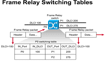
6.4. Frame Relay Subinterfaces
6.4.1. What are Frame Relay subinterfaces ?
To enable the sending of complete
routing updates in a Frame Relay network, you can configure the router with
logically assigned interfaces called subinterfaces. Subinterfaces are logical
subdivisions of a physical interface. In a subinterface configuration, each PVC
can be configured as a point-to-point connection. This allows the subinterface
to act as a dedicated line, as shown in Figure ![]() .
.
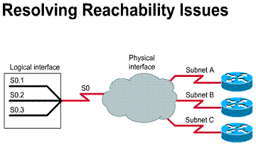 As shown in Figure
 ![]() ,
a single router interface can service many remote locations through individual
unique subinterfaces.
,
a single router interface can service many remote locations through individual
unique subinterfaces.
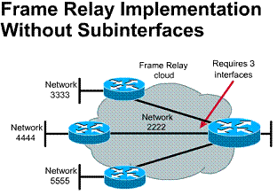
1) A single physical interface can be
split into multiple logical interfaces
2) Subinterfaces can resolve split horizon issues
3) Routing updates can be sent out subinterfaces as if they were separate physical interfaces
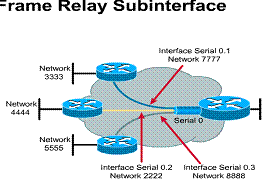
6.4.2. Split horizon routing environments
![]() As
a result, if a remote router sends an update to the headquarters router that is
connecting multiple PVCs over a single physical
interface, the headquarters router cannot advertise that route through the same
physical interface to other remote routers.
As
a result, if a remote router sends an update to the headquarters router that is
connecting multiple PVCs over a single physical
interface, the headquarters router cannot advertise that route through the same
physical interface to other remote routers. ![]()
![]()
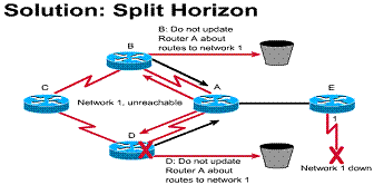
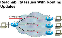
With simple split horizon, routing
updates sent to a particular neighbor router should not contain information
about routes that were learned from that neighbor. For example, suppose
Router 1 advertises that it has a route to network A. Router 2 receives the
update from Router 1 and inserts the information about network A in its routing
table. When Router 2 sends a regular routing update, it does not include
the entry for Network A in the update sent to Router 1 because that route
was learned from Router 1 in the first place. Routing update received
at a central router cannot be advertised out the same physical interface to
other routers (split horizon) If you learn a protocol's
route on an interface, do not send information about that route back to the
interface
6.4.3. The resolution of point-to-point and multipoint reachability issues
You can configure subinterfaces to support the following connection types:
6.5. The Configuration of Basic Frame Relay
6.5.1. Writing the IOS command sequence to completely configure Frame Relay
A basic Frame Relay configuration
assumes that you want to configure Frame Relay on one or more physical
interfaces ![]() and
that LMI and Inverse ARP are supported by the remote router(s). In this type of
environment, the LMI notifies the router about the available DLCIs. Inverse ARP
is enabled by default, so it does not appear in configuration output. Figure
and
that LMI and Inverse ARP are supported by the remote router(s). In this type of
environment, the LMI notifies the router about the available DLCIs. Inverse ARP
is enabled by default, so it does not appear in configuration output. Figure ![]() illustrates
the steps to configure basic Frame Relay.
illustrates
the steps to configure basic Frame Relay.
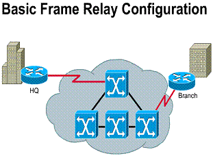
|
Step 1 |
Select the interface and go into interface configuration mode: router(config)#ip address 192.168.38.40 255.255.255.0 |
|
Step 2 |
Configure a network-layer address, for example, an IP address: router(config-if)#ip address 192.168.38.40 255.255.255.0 |
|
Step 3 |
Select the encapsulation type used to encapsulate data traffic end-to-end: router(config-if)#encapsulation frame-relay[cisco | IETF] where Cisco is the default, which you use if connecting to another Cisco router. Ietf is used for connecting to a non-Cisco router. |
|
Step 4 |
If you're using Cisco IOS Release 11.1 or earlier, specify the LMI type used by the Frame Relay switch: router(config-if)#frame-relay lmi-type where cisco is the default. With IOS Release 11.2 or later, the LMI type is autosensed, so no configuration is needed. |
|
Step 5 |
Configure the bandwidth for the link: router(config-if)#bandwidth kilobits. This command affects routing operation by protocols such as IGRP, because it is used to define the metric of the link. |
|
Step 6 |
IF Inverse ARP was disabled on the router, re-enable it(Inverse ARP is on byb default): router(config-if)#frame-relay inverse-arp [protocol] [dlci] Where protocol is the supported protocols, including IP, IPX, AppleTalk, DECnet, VINES and XNS. dlci is the DLCI on the local interface that you want to exchange Inverse ARP messages. |
6.5.2. The commands for verifying Frame Relay operation
After configuring Frame Relay, you can verify that the connections are active by using the show commands shown in the Figure.
|
Command |
Description |
|
show interfaces serial |
Displays information about the multicast DLCI, the DLCIs used on the Frame Relay-configured serial interface, and the LMI DLCI used for the LMI. |
|
show frame-relay pvc |
Displays the status of each configured connection as well as traffic statistics. This command is also useful for viewing the number of BECN and FECN packed received by the router. |
|
show frame-relay map |
Displays the network-layer address and associated DLCI for each remote destination that the local router is connected to. |
|
show frame-relay lmi |
Displays LMI traffic statistics. For example, it shows the number of status messages exchanged between the local router and the Frame Relay switch, |
6.5.3. The steps in confirming that the Frame Relay line is up
Complete the steps shown in the Figure to confirm that the line is up.
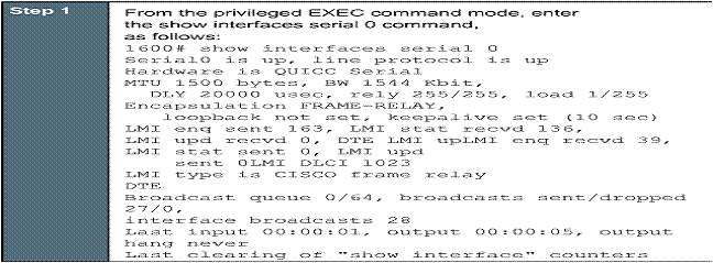

|
Step 2 |
Confirm that the following messages appear in the command output: -Serial0 is up, line protocol is up -The Frame Relay connection is active. -LMI enq sent 163, LMI stat recvd 126 -The connection is sending and receiving data. The number shown in your output will probably be different. -LMI type is CISCO-The LMI type is configured correctly for the router. |
|
Step 3 |
If the message does not appear in the command output, take the following steps: Confirm with the Frame Relay service provider that the LMI setting is correct for your line. Confirm that keepalives are set and that the router is receiving LMI updates. |
|
Step 4 |
To continue configuration, reenter global configuration mode. |
6.5.4. The steps in confirming the Frame Relay maps
Complete the steps shown in the Figure to confirm the Frame Relay maps.
|
Step 1 |
From privileged EXEC mode, enter show frame-relay map command. Confirm that the status is defined, active message (shown in bold in the example) appears for each serial subinterface: 1600#show frame-relay map Serial0.1 (up): point-to-point dlci, dlci 17(0x11,0x410), broadcast, status defined, active |
|
Step 2 |
If the message does not appear, follow these steps:
|
|
Step 3 |
To continue configuration, reenter global configuration mode. |
6.5.5. The steps in confirming connectivity to the central site router
Complete the steps shown in the Figure to confirm connectivity to the central site router.
|
Step 1 |
From privileged EXEC mode, enter the ping command, followed by the IP address of the central site router. |
|
Step 2 |
Note the percentage in the Success rate. line(shown in bold in the example): 1600#ping 192.168.38.40 Type escape sequence to abort. Sending 5, 100-byte ICMP Echos to 192.168.38.40, timeout is 2 seconds: Success rate is 100 percent (5/5), Round-trip min/avg/max = 32/32/32 ms If the success rate is 10% or greater, this verification step is successful |
|
Step 3 |
To continue, reenter global configuration mode. |
6.5.6. The steps you must use to configure the serial interface for a Frame Relay connection
Use the steps shown in the Figure to configure the serial interface for Frame Relay packet encapsulation.
|
Step 1 |
Enter configuration mode for the serial interface: 1600(config)#interface serial 0 |
|
Step 2 |
Set the encapsulation method on this interface to Frame Relay: 1600(config-if)#encapsulation frame-relay |
|
Step 3 |
Enable the configuration changes on this interface: 1600(config-if)#no shutdown |
6.5.7. The steps in verifying a Frame Relay configuration
As shown in the Figure, you can verify your configuration to this point by confirming that an active PVC is active on the Frame Relay line
6.5.8. The steps in configuring Frame Relay subinterfaces
To configure subinterfaces on a
physical interface as shown in Figure ![]() follow
the steps in Figure
follow
the steps in Figure ![]() .
(Figures
.
(Figures ![]()
![]() are
referenced in Figure
are
referenced in Figure ![]() )
)
6.5.9. Optional Frame Relay commands
The commands shown in the Figure ![]() can
be used when necessary for enhanced router operation.
can
be used when necessary for enhanced router operation.
Normally, Inverse ARP is used to
request the next-hop protocol address for a specific connection. Responses to
Inverse ARP are entered in an address-to-DLCI map (that is, Frame Relay map)
table, as shown in Figure ![]() .
The table is then used to route outgoing traffic. There are three instances
when you must define the address-to-DCLI table statically:
.
The table is then used to route outgoing traffic. There are three instances
when you must define the address-to-DCLI table statically:
The static entries are referred to as static maps.
With Frame Relay, you can increase or decrease the keepalive interval. You can extend or reduce the interval at which the router interface sends keepalive messages to the Frame Relay switch. The default is 10 seconds, and the following is the syntax:
router(config-if)#
keepalive number
where number is the value, in seconds, that is usually 2 to 3 seconds faster (that is, a shorter interval) than the setting of the Frame Relay switch to ensure proper synchronization.
If an LMI type is not used in the network, or when you are doing back-to-back testing between routers, you need to specify the DLCI for each local interface by using the following command:
router(config-if)#
frame-relay
local-dlci number
where number is the DLCI on the local interface to be used
|
Parameter |
Description |
|
Protocol |
Defines the supported protocol, bridging, or logical link protocol. |
|
Protocol-address |
Defines the network-layer address of the destination router interface. |
|
dlci |
Defies the local DLCI used to connect to the remote protocol address. |
|
broadcast |
(Optional) Forwards broadcasts to this address when multicast is not enabled. Use this if you want the router to forward routing updates. |
|
istf | cisco |
(Optional) Select the Frame Relay encapsulation type for use. Use ietf only if the remote router is a non-Cisco router. Otherwise, use cisco. |
|
Payload-compress Packet-by-packet |
(Optional) Packet-by-packet payload compression using the Stacker method. |
Chapter 7
Overview
Selecting, installing, and testing cable, as well as wiring closet determination, are all skills important in network design and implementation. Network maintenance and troubleshooting skills complete the picture. In addition, it is important to know when it is necessary to expand or change the network configuration in order to meet the changing demands placed on it. This chapter teaches network management skills using techniques such as documenting, monitoring, and troubleshooting.
The Administrative Side of Network Management
What does a network look like?
The view of a network is important. A
network is a collection of devices that interact with one another to provide communication.
When a network administrator looks at a network, it should be as a whole
instead of individual parts. In other words, each device in a network affects
other devices and the network as a whole. Nothing is isolated when connected to
a network. ![]()
A good comparison would be an automobile. A car is a collection of parts that provides transportation. The engine provides power to move the car, but the engine does not work very well if the fuel system is not functioning or the tires are missing. Brakes are also important components, but without the hydraulic system the brakes do not function and the car does not stop. All the components must work together in order for the car to perform its designated task of transportation.
The same is true with a network system.
If the network server is set up to work with the IPX/SPX protocol and the hosts
are not, there will be no communication. Also, if the system is working fine
and the administrator changes the protocols on only one end, the system stops
working.![]() One device affects how other devices function. Communication failure can also
occur when a host is configured to find the DNS server at an incorrect IP
address. A DNS server could be located at IP address 192.150.11.123 and all
hosts are configured to find the DNS server at this IP address. If a network
technician changes the IP address of the DNS server without changing the
configuration at the host, the hosts will no longer have DNS services.
One device affects how other devices function. Communication failure can also
occur when a host is configured to find the DNS server at an incorrect IP
address. A DNS server could be located at IP address 192.150.11.123 and all
hosts are configured to find the DNS server at this IP address. If a network
technician changes the IP address of the DNS server without changing the
configuration at the host, the hosts will no longer have DNS services.
The important thing to remember when
dealing with a network is to view it as a single unit compared to a group of
individually connected devices. This also applies to the wide area connections
that are used when connecting to the Internet. Changes that are made to the
routers at one location will directly affect the efficiency and reliability of
communication throughout the entire system. ![]()
7.1.2. Understanding and establishing the boundaries of the network
In an enterprise network it is important that the network staff knows its responsibilities. Is it the responsibility of the network staff to diagnose problems on the user's desktop, or simply to determine that the user's problem is not communication related. Does the network staff's responsibility for support extend only as far as the horizontal cabling wall plate, or does their responsibility extend all the way to the NIC?
These definitions are very important to a networking department. They affect the workload of each person and the cost of network services for the enterprise. The greater the responsibility of a network staff, the greater the resource cost. Imagine a restaurant owned and operated by a single individual. This person is responsible for all tasks, including cooking, serving, washing dishes, and paying the bills. The human resource cost of the restaurant is relatively low. Possibilities for growth and expansion are limited until the owner hires cooks, waiters, busboys, and accountants. Once responsibilities are divided, the restaurant can serve more people in a more efficient manner. The tradeoff, of course, is that resource costs have risen along with the growth and expansion.
The restaurant example shows that the job of network support can encompass all aspects of the network, or it can be limited to just certain components. These responsibilities need to be defined and enforced on a department by department basis. The key to understanding this relationship is recognizing that making the responsibility area too large may overburden the resources of the department. Making the area too small may make it difficult to effectively resolve the problems on the network
7.1.3. Costs of a network
Network administration encompasses many responsibilities, including cost analysis. This means determining the cost of network design and implementation. It also includes the cost of maintaining, upgrading, and monitoring the network. Determining the cost of network installation is not a particularly difficult task for most network administrators. Equipment lists and costs may be readily established. Labor costs can be calculated using fixed rates. Unfortunately, the cost of building the network is only one aspect to consider when calculating the final costs.
There are some of the other cost factors that must be considered. These include network growth over time, technical and user training, repairs, and software deployment. These costs are much more difficult to project than the cost of building the network. The network administrator must be able to look at historical and company growth trends to project the cost of growth in the network. A manager must look at new software and hardware to determine if the company will need to implement them and when. Staff training will need to support these new technologies.
The cost of redundant equipment for mission critical operations should also be added to the cost of maintaining the network. Think of running an Internet based business that uses a single router to connect to the Internet. If that router fails, your company is out of business until that router is replaced. This could cost the company thousands of dollars in lost sales. A wise network administrator might keep a spare router on the premises to minimize the time the company is offline.
7.1.4. Error report documentation
As mentioned in the previous semester, effective network management requires thorough documentation. When problems arise, some form of error document should be generated. This document is used to gather the basic information necessary to identify and assign a network problem. This will also provide a way of tracking the progress and eventual solution of the problem. Problem reports provide justification to senior management for hiring new staff, purchasing equipment, and providing additional training. This documentation also provides solutions to recurring problems that have already been resolved.
All of the material presented so far in this chapter has dealt with the non-technical issues of network management. The rest of the chapter will deal with the tools that are available to monitor and diagnose problems on a wide-area network

7.2. Why is it necessary to monitor a network?
7.2.1. Why is it necessary to monitor a network?
There are many reasons for network monitoring. Two primary reasons are predicting changes for future growth and detecting unexpected changes in network status. Unexpected changes might include things such as a router or switch failing, a hacker trying to gain illegal access to the network, or a communication link failure. Without the ability to monitor the network, an administrator can anticipate problems and prevent them from occurring. Without this ability, the administrator can only react to problems as they occur.
In the previous semester network management topics were covered with primary focus on local-area networking. Monitoring a wide-area network involves many of the same basic management techniques as managing a local-area network. One of the major differences in a WAN-LAN comparison is the physical placement of equipment. The placement and use of monitoring tools becomes critical to the uninterrupted operation of the wide-area network
7.2.2. Connection monitoring
One of the most basic forms of connection monitoring takes place every day on a network. Connections work properly when users are able to logon to the network. If users cannot logon, the networking department will soon be contacted. This is not the most efficient or the most preferable method of connection monitoring available. Simple programs are available that will allow the administrator to enter a list of host IP addresses. These addresses will be periodically pinged. If there is a connection problem, the program will alert the administrator as determined by the results of the ping request. This is a very inefficient and primitive way of monitoring the network, but it will work better than nothing at all. This type of monitoring can only determine that there is a communication breakdown somewhere between the monitoring station and the target device. The fault could be a bad router, switch, network segment, or the actual host might be down. The ping test only says that the connection is down, not where it is down.
Checking all the hosts on a WAN using
this type of monitoring uses many resources. If the network has 3000 hosts on
it, pinging all of the network devices and hosts can use a great deal of system
resources. A better way is to ping just a few of the important hosts, servers,
routers, and switches to verify their connectivity.
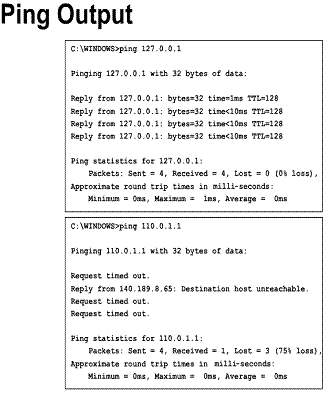
7.2.3. Traffic monitoring
Traffic monitoring is a more sophisticated method of network monitoring. It looks at the actual packet traffic on the network and generates reports based upon the network traffic. Programs such as Microsoft Windows NT Network Monitor and Fluke's Network Analyzer are examples of this type of software. These programs not only detect failing equipment, but also determine if a component is overloaded or poorly configured. The drawback to this type of program is that it normally works on a single segment at a time. If data needs to be gathered from other segments the monitoring software must be moved to that segment. This can be overcome by the use of agents on the remote network segments as shown in the Figure. Equipment such as switches and routers have the ability to generate and transmit traffic statistics as part of their operating system. So, how is the data gathered and organized in such a manner as to be useful to the centralized network administrator? The answer is: Simple Network Management Protocol (SNMP).
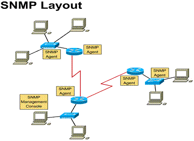
7.2.4. Simple network management protocol
SNMP is a protocol that allows the transmission
of statistical data over the network to a central management console. SNMP is a
component of the Network Management Architecture. The Network Management
Architecture consists of four major components. ![]()
The management station is the network manager's interface into the network system. It has the programs to manipulate and control data from the network. The management station also maintains a database of management information base (MIB) extracted from the devices under its management.
The management agent is the component that is contained in the devices that are to be managed. Bridges, routers, hubs, and switches may contain SNMP agents to allow them to be controlled by the management station. The management agent responds to the management station in two ways. First, through polling, the management station requests data from the agent and the agent responds with the requested data. Trapping is a data gathering method designed to reduce traffic on the network and processing on the devices being monitored. Instead of the management station polling the agents at specific intervals continuously, thresholds (top or bottom limits) are set on the managed device. If this threshold on the device is exceeded, the managed device will send an alert message to the management station. This eliminates the need to continuously poll all of the managed devices on the network. Trapping is very beneficial on networks with a large number of devices that need to be managed. It reduces the amount of SNMP traffic on the network to provide more bandwidth for data transfer.
The management information base has a database structure and is resident on each device that is managed. The database contains a series of objects, which are resource data gathered on the managed device. Some of the categories in the MIB include Port interface data, TCP data, and ICMP data.
The network management protocol used is SNMP. SNMP is an application layer protocol designed to communicate data between the management console and the management agent. It has three key capabilities: GET, PUT, and TRAP. GET allows the management console to retrieve data from the agent. With PUT, the management console sets object values on the agent. Finally there is TRAP, where the agent notifies the management console of significant events.
The key word to remember in Simple
Network Management Protocol is Simple. When SNMP was developed, it was designed
to be a short-term system that would later be replaced. But just like TCP/IP,
it has become one of the major standards in Internet-Intranet management configurations.
Over the last few years, enhancements have been added to SNMP to expand its
monitoring and management capabilities. One of the greatest enhancements to
SNMP is called Remote Monitoring (RMON). RMON extensions to SNMP give the
ability to look at the network as a whole as opposed to looking at individual
devices. ![]()
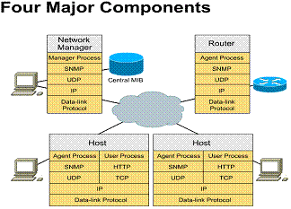
RMON Extensions
1. The Ethernet Statistics Group
2. The History Control Group
3. The Alarm Group
4. The Host Group
5. The HostTop Group
6. The Matrix Group
7. The Filter Group
8. The Packet Group
9. The Event Group
10.The Token-Ring Group
7.2.5. Remote monitoring (RMON)
Probes gather remote data in RMON. A
probe has the same function as a SNMP agent. A probe has RMON capabilities; an
agent does not. When working with RMON, as with SNMP, a central management
console is the point of data collection. An RMON probe is located on each
segment of the network being monitored. These probes can be dedicated hosts,
resident on a server, or included in a standard networking device such as a
router or switch. These probes gather the specified data from each segment and
relay it to the management console. ![]()
Redundant management consoles provide
two major benefits to network management processes. First is the ability to
have more than one network administrator in different physical locations monitor
and manage the same network. For example, one network administrator could be in
![]()
The RMON extension to the SNMP protocol
creates new categories of data. These categories add more branches to the MIB
database. Each of the major categories will be explained in the following list.
![]()
Contains statistics gathered for each monitored subnetwork. These statistics include counters (incremental that start from zero) for bytes, packets, errors, and frame size. The other type of data reference is an index table. The table identifies each monitored Ethernet device, allowing counters to be kept for each individual Ethernet device. The Ethernet Statistics Group provides a view of the overall load and health of a subnetwork. It does this by measuring different types of errors including CRC, collisions, and over and under-sized packets.
Contains a data table that will record samples of the counters in the Ethernet Statistics Group over a specified period of time. The default time set up for sampling is every thirty minutes (1800 seconds). The default table size is fifty entries. The total is twenty-five hours of continuous monitoring. As the history is created for the specified counter, a new entry is created in the table at each sample interval until the limit of fifty is reached. Then as each new entry is created the oldest entry in the table is deleted. These samples provide a baseline of the network. These samples can be used to compare against the original baseline to resolve problems or to update the baseline as the network changes.
Uses user specified limits that are called thresholds. If the data counters being monitored cross the thresholds, a message or alarm will be sent to the specified people. This process, known as an error trap, can automate many functions of network monitoring. Without error trap, a person would have to constantly and directly monitor the network or wait for a user to identify a problem with the network. With error trap, the network process itself can send messages to the network personnel because of a failure or, more importantly, an impending failure. This is an important component of preemptive troubleshooting.
Contains counters maintained about each host discovered on the subnetwork segment. Some of the counter categories maintained are Packets, Octets, Errors, and Broadcasts. Types of counters associated with each of the previously mentioned items could be, for example, total packets, packets received, packets sent, along with many counters specific to the type of item.
Is used to prepare reports about a group of hosts that top a statistical list based on a measured parameter. The best way to describe this group is by example. A report could be generated for the top ten hosts generating broadcasts for a day. Another report might be generated for the most packets transmitted during the day. This category provides an easy way to determine who and what type of data traffic most occupies the selected subnetwork.
Records the data communication between two hosts on a subnetwork. This data is stored in the form of a matrix (a multi-dimensional table). One of the reports that can be generated from this category is which host utilizes a server. Reorganizing the matrix order can create other reports. For example, one report might show all users of a particular server, while another report shows all the servers used by a particular host.
Provides a way that a management console can instruct an RMON probe to gather selected packets from a specific interface on a particular subnetwork. This selection is based on the use of two filters, the DATA and the STATUS filter. The data filter is designed to match or not match particular data patterns allowing for the selection of that particular data. The status filter is based on the type of packet looked at. This means, for example, a CRC packet or a Valid packet. These filters can be combined using logical "and" and "or" to create very complicated conditions. The filter group allows the network administrator to selectively look at different types of packets to provide better network analysis and troubleshooting.
Allows the administrator to specify a method to use to capture packets that have been selected by the Filter Group. By capturing specified packets the network administrator can look at the exact detail for packets that meet the basic filter. The packet group also specifies the quantity of the individual packet captured and the total number of packets captured.
Contains events generated by other groups in the MIB database. An example could be that a counter is exceeding the threshold for that counter specified in the Alarm Group. This action would generate an event in the Event Group. Based upon this event an action could be generated, such as issuing a warning message to all the people listed in the Alarm Groups parameters or creating a logged entry in the event table. An event is generated for all comparison operations in the RMON MIB extensions.
Contains counters specific to token ring networks. While most of the counters in the RMON extensions are not specific to any type of data link protocol, the Statistics and History groups are. They are particularly attuned to the Ethernet protocol. The Token Ring Group creates counters necessary to monitor and manage token ring networks using RMON.
It is important to remember that RMON is an extension to the SNMP protocol. Specifically, this means that while RMON enhances the operation and monitoring capabilities of SNMP, SNMP is still required for RMON to operate on a network. As a last point, it is important to mention that there are later revisions of both SNMP and RMON. They are labeled as SNMPv2 and RMON2. This curriculum does not cover all the new capabilities of these versions
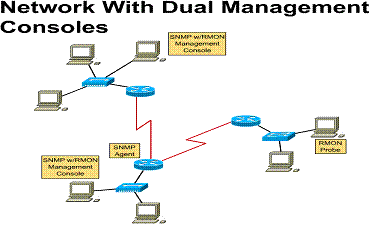
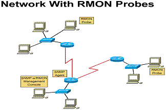
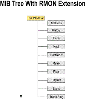
7.3. Troubleshooting Networks
7.3.1. Problem solving
Problems happen. Even when the network
is monitored, the equipment is reliable, and the users are careful, things may
go wrong. The test of a good network administrator is the ability to analyze,
troubleshoot, and correct problems under pressure of a network failure that
causes company downtime. Good network administration techniques were described
in Semester 3. The suggestions below review those techniques as well as offer
other tools for troubleshooting a network. These techniques as stated before
can be the best tools in curing network problems. ![]()
The first and most important thing is
to use the engineering journal for taking notes. Taking notes can define a
clear path to diagnosing a problem. Taking notes can reveal what has already
been attempted and what effect it had on the problem. A copy of these notes
should be included with the resolution of the problem when the trouble ticket
on this job is completed. Future troubleshooting of similar problems can then
benefit from previous work, saving time and frustration, even with different
technicians are involved. ![]()
Another essential element of preemptive troubleshooting is labeling. Label everything, including both ends of a horizontal cable run. This label should include the number of the cable, where the other end is located, and the usage of the cable. Usage, for example, might include voice, data or video. This type of label can be even more valuable than a wiring cut sheet when it comes to troubleshooting, because it is located right where the unit is and not stuck in a drawer somewhere. Labeling each port on a hub, switch or router as to location, purpose, and point of connection will greatly improve the ease with which problems can be solved. Finally, all other components attached to the network should also be labeled as to their location and purpose. With this type of labeling, all components can be located and their purpose on the network easily defined. Proper labeling, used with the network documentation created when the network was built and updated, will give a complete picture of the network and its relationships. One other important reminder from the previous semester is that the documentation is only useful if it is current. All changes made to the network must be documented on both the device or wire that is changed and the paper documentation used to define the complete network.
The first step in network troubleshooting is the definition of the problem. This definition can be a consolidation of many different sources. One of the sources could be a trouble ticket or help desk report, which initially identifies a problem. Another might be a phone conversation with the user having the problem to gather more information about the problem. Network monitoring tools may provide a more complete idea about the specific problem to be resolved. Other users and observations will provide information. Evaluating all of this information may give the troubleshooter a much clearer starting place to resolve the problem, rather than by working from any one of the sources alone.
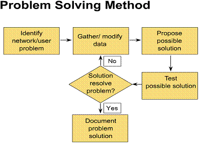
7.3.2. Troubleshooting methods
The Process of Elimination technique, along with the Divide and Conquer technique, are the most successful methods for networking troubleshooting. The following scenarios explain these techniques.
The Process of Elimination technique will be applied to the following problem:
A user on the network calls the help desk to report that their computer can no longer get to the Internet. The help desk fills out the error report form and forwards it to the network support department.
The user informs the support department
in a telephone call that they have done nothing differently in attempting to connect
to the Internet. The support person checks the hardware logs for the network
and find out that the user's computer was upgraded last night. An assumption is
made that the computer network drivers must be incorrectly configured. The
network configuration on the computer is then checked. It appears as if it is
correct, so a ![]()
The next solution is to check to see if
the workstation cable is plugged in. Both ends of the cable are checked and a
Next 127.0.0.1 is pinged, which is the loopback address for the computer. The ![]()
The support person then decides that
there might be a problem with the server for this network segment. There is
another networked computer at the next desk, so the server address is pinged
from there and the result is successful. This eliminates the server, the
backbone, and the server connection to the backbone as the problem. ![]()
The support person then goes to the IDF
and switches the port for the workstation. A ![]()
After replacing the workstation cable,
the ![]()
The last step is to document the problem solution on the error report form and return it to the help desk so it can be logged as completed.
The Divide and Conquer technique will be applied to this problem:
Two networks work fine when not
connected, but when joined the entire combined network fails. Refer to the
diagram for reference. ![]()
The first step would be to divide the
network back into two separate networks and verify that the two still operate
correctly when separated. If this is true then remove all of the subnet
connections for one of the connecting routers and reconnect it to the other
working network. Verify that it is still working correctly. ![]()
If the network is still functioning,
add each of the subnetworks for that router back into
the router until the overall system fails. Remove the last subnet that was
added and see if the whole network returns to normal operation. ![]()
If the network is again functioning
normally, remove the hosts from the network segment and replace them one at a
time, again checking to see when the network fails. When the offending device
is found, remove it and verify that the network returns to normal. ![]()
If the network is still functioning
normally, the faulty piece of equipment has been isolated. It is now possible
to troubleshoot this individual piece of equipment to find out why it was
causing the entire network to crash. If nothing proves to be wrong with this
device upon analysis, it may be that this device in conjunction with another
device on the opposite network is causing the problem. To find the other end of
the problem the process that was used above would have to be repeated. This is
that process: ![]()
First reconnect the host that caused
the network to fail. Then disconnect all of the subnetworks
from the other router. Check that the network has returned to operating status.
![]()
If the network is functioning again, add each of the subnetworks for that router back into the router until the overall system fails. Remove the last subnet that was added before the failure and see if the whole network returns to normal operation.
If the network is again functioning
normally, remove the hosts from the network segment and replace them one at a
time, again checking to see when the network fails. When the offending device
is found, remove it and verify that the network returns to normal. ![]()
![]()
If the network is still functioning
normally, the faulty piece of equipment has been isolated. It is now possible
to troubleshoot this individual piece of equipment to find out why it was
causing the entire network to crash. If nothing proves to be wrong with this
device upon analysis, compare the two hosts and find the reason for their
conflict. By resolving this conflict, both stations can be reconnected into the
network and it will still function normally. ![]()
Software tools
Along with the processes that were described previously, there are software tools that are available for use by the network administrator to solve network connectivity problems. These tools can help in local-area network troubleshooting, but are especially helpful in a wide-area network troubleshooting situation.
We will look at the commands that are
available to a network administrator in most client software packages. These
commands include the Ping,
Tracert (Traceroute),
Telnet, Netstat, ARP, and IPconfig (WinIPcfg). ![]()
Sends ICMP echo packets to verify connections to a remote host. Figure ![]() displays
output from a successful ping. The output shows the number of packets responded
to and the return time of the echo.
displays
output from a successful ping. The output shows the number of packets responded
to and the return time of the echo.
|
-t |
ping until interrupted |
|
-a |
resolves host name and ping address |
|
-n |
count limits number of echo packets sent |
|
-l |
length specifies size of echo packets sent |
|
-f |
DO NOT FRAGMENT command sent to gateways |
|
-i |
ttl sets the TTL field |
|
-r |
count records the route of the outgoing and returning packets |
|
destination |
specifies the remote host to ping, by domain name or by IP address |
Tracert (Traceroute)
This utility shows the route a packet took to reach its destination. Figure ![]() displays
output from a tracert command.
displays
output from a tracert command.
Tracert [-d] [-h maximum_hops] [-j host-list] [-w timeout] target_name
|
-d |
specifies IP addresses shouldn't be resolved to host names |
|
-h |
maximum_hops limits the number of hops searched |
|
-j |
host-list specifies the loose source route |
|
-w |
timeout waits the number of milliseconds specified for each reply |
|
target_name |
target_name specifies remote host tracing too, by domain name or by IP address |
Telnet
This is a terminal emulation program that allows interactive commands on the
telnet server. Until a connection is established, no data will pass. If the
connection should break, telnet will inform you. Telnet is good for testing
login configuration parameters to a remote host. ![]()
|
Telnet destination |
destination specifies remote host telnetting to, by domain name or IP address Netstat Netstat displays protocol
statistics and current TCP/IP network connections. Netstat [-a] [-e] [-n] [-s] [-p proto] [-r] [interval] |
|
-a |
Displays all connections and listening ports. (Server-side connections are normally not shown). |
|
-e |
Displays Ethernet statistics. This may be combined with the -s option. |
|
-n |
Displays addresses and port numbers in numerical form. |
|
-p |
Shows connections for the protocol specified by proto proto may be tcp or udp. If used with the -s option to display per-protocol statistics, proto may be tcp, udp, or ip. |
|
-r |
Displays the contents of the routing table. |
|
-s |
Displays per-protocol statistics. By default, statistics are shown for TCP, UDP and IP; the -p option may be used to specify a subset of the default. |
|
interval |
Redisplays selected statistics, pausing interval seconds between each display. Press CTRL+C to stop redisplaying statistics. If omitted, Netstat will print the current configuration information once. |
ARP
ARP is used to gather hardware addresses of local hosts and the default
gateway. The ARP cache can be viewed and checked for invalid or duplicate
entries. ![]()
arp -a [inet_addr] [-N [if_addr]] arp -d inet_addr [if_addr] arp -s inet_addr ether_addr [if_addr]
|
-a or -g |
displays the current contents of the arp cache |
|
-d |
deletes the entry specified by inet_addr |
|
-s |
adds a static entry to the cache |
|
-N |
displays the arp entries for the specified physical address |
|
inet_addr |
IP address, in dotted decimal format |
|
if_addr |
IP address whose cache should be modified |
|
ether_addr |
the MAC address in hex separated by hyphens |
IPconfig (Windows NT)/WinIPcfg (Windows 95-98)
These Windows utilities display IP addressing information for the local network
adapter(s) or a specified NIC. ![]()
IPconfig [/all | /renew [adapter] | /release [adapter]]
|
/all |
all information about adapter(s) |
|
/renew |
renew DHCP lease information for all local adapters if none is named |
|
/release |
release DHCP lease information disabling TCP/IP on this adapter |
|