ALTE DOCUMENTE |
|
|
|
|
|||||
|
|
|
Overview |
|||||
Ethernet has been the most successful LAN technology mainly because of how easy it is to implement. Ethernet has also been successful because it is a flexible technology that has evolved as needs and media capabilities have changed. This module will provide details about the most important types of Ethernet. The goal is to help students understand what is common to all forms of Ethernet.
Changes in Ethernet have resulted in major improvements over the 10-Mbps Ethernet of the early 1980s. The 10-Mbps Ethernet standard remained virtually unchanged until 1995 when IEEE announced a standard for a 100-Mbps Fast Ethernet. In recent years, an even more rapid growth in media speed has moved the transition from Fast Ethernet to Gigabit Ethernet. The standards for Gigabit Ethernet emerged in only three years. A faster Ethernet version called 10-Gigabit Ethernet is now widely available and faster versions will be developed.
MAC addresses, CSMA/CD, and the frame format have not been changed from earlier versions of Ethernet. However, other aspects of the MAC sublayer, physical layer, and medium have changed. Copper-based NICs capable of 10, 100, or 1000 Mbps are now common. Gigabit switch and router ports are becoming the standard for wiring closets. Optical fiber to support Gigabit Ethernet is considered a standard for backbone cables in most new installations.
This
module covers some of the objectives for the CCNA 640-801, INTRO 640-821, and
ICND 640-811 exams. ![]()
Students
who complete this module should be able to perform the following tasks: ![]()
Describe the basic architectural considerations of Gigabit and 10-Gigabit Ethernet
|
|
|
|
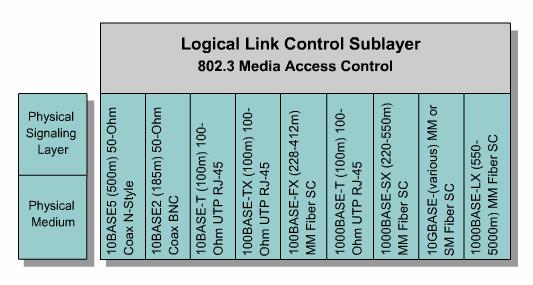
This page will discuss 10-Mbps Ethernet technologies.
10BASE5,
10BASE2, and 10BASE-T Ethernet are considered Legacy Ethernet. ![]() The four common
features of Legacy Ethernet are timing parameters, the frame format,
transmission processes, and a basic design rule.
The four common
features of Legacy Ethernet are timing parameters, the frame format,
transmission processes, and a basic design rule.
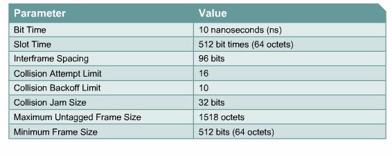
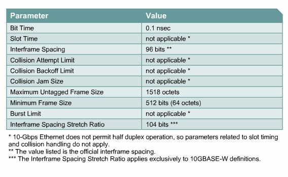
Figure
![]() displays the
parameters for 10-Mbps Ethernet operation. 10-Mbps Ethernet and slower versions
are asynchronous. Each receiving station uses eight octets of timing
information to synchronize its receive circuit to the
incoming data. 10BASE5, 10BASE2, and 10BASE-T all share the same timing
parameters. For example, 1 bit time at 10 Mbps = 100 nanoseconds (ns) = 0.1
microseconds = 1 10-millionth of a second. This means that on a 10-Mbps
Ethernet network, 1 bit at the MAC sublayer requires 100 ns to transmit.
displays the
parameters for 10-Mbps Ethernet operation. 10-Mbps Ethernet and slower versions
are asynchronous. Each receiving station uses eight octets of timing
information to synchronize its receive circuit to the
incoming data. 10BASE5, 10BASE2, and 10BASE-T all share the same timing
parameters. For example, 1 bit time at 10 Mbps = 100 nanoseconds (ns) = 0.1
microseconds = 1 10-millionth of a second. This means that on a 10-Mbps
Ethernet network, 1 bit at the MAC sublayer requires 100 ns to transmit.
For all speeds of Ethernet transmission 1000 Mbps or slower, transmission can be no slower than the slot time. Slot time is just longer than the time it theoretically can take to go from one extreme end of the largest legal Ethernet collision domain to the other extreme end, collide with another transmission at the last possible instant, and then have the collision fragments return to the sending station to be detected.
10BASE5,
10BASE2, and 10BASE-T also have a common frame format. ![]()
The Legacy Ethernet transmission process is identical until the lower part of the OSI physical layer. As the frame passes from the MAC sublayer to the physical layer, other processes occur before the bits move from the physical layer onto the medium. One important process is the signal quality error (SQE) signal. The SQE is a transmission sent by a transceiver back to the controller to let the controller know whether the collision circuitry is functional. The SQE is also called a heartbeat. The SQE signal is designed to fix the problem in earlier versions of Ethernet where a host does not know if a transceiver is connected. SQE is always used in half-duplex. SQE can be used in full-duplex operation but is not required. SQE is active in the following instances:
All
10-Mbps forms of Ethernet take octets received from the MAC sublayer and
perform a process called line encoding. Line encoding describes how the bits
are actually signaled on the wire. The simplest encodings have undesirable
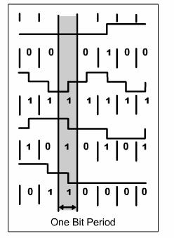
timing and electrical characteristics. Therefore, 939i83j line codes have been designed
with desirable transmission properties. This form of encoding used in 10-Mbps
systems is called
![]() , the top waveform
moves to a lower position so it is interpreted as a binary zero. The second
waveform moves to a higher position and is interpreted as a binary one. The
third waveform has an alternating binary sequence. When binary data alternates,
there is no need to return to the previous voltage level before the next bit
period. The wave forms in the graphic show that the binary bit values are
determined based on the direction of change in a bit period. The voltage levels
at the start or end of any bit period are not used to determine binary values.
, the top waveform
moves to a lower position so it is interpreted as a binary zero. The second
waveform moves to a higher position and is interpreted as a binary one. The
third waveform has an alternating binary sequence. When binary data alternates,
there is no need to return to the previous voltage level before the next bit
period. The wave forms in the graphic show that the binary bit values are
determined based on the direction of change in a bit period. The voltage levels
at the start or end of any bit period are not used to determine binary values.
Legacy Ethernet has common architectural features. Networks usually contain multiple types of media. The standard ensures that interoperability is maintained. The overall architectural design is most important in mixed-media networks. It becomes easier to violate maximum delay limits as the network grows. The timing limits are based on the following types of parameters:
10-Mbps Ethernet operates within the timing limits for a series of up to five segments separated by up to four repeaters. This is known as the 5-4-3 rule. No more than four repeaters can be used in series between any two stations. There can also be no more than three populated segments between any two stations.
|
|
|
|
|||
|
|
|
|
This page will discuss the original 1980 Ethernet product, which is 10BASE5. 10BASE5 transmitted 10 Mbps over a single think coaxial cable bus.
10BASE5 is important because it was the first medium used for Ethernet. 10BASE5 was part of the original 802.3 standard. The primary benefit of 10BASE5 was length. 10BASE5 may be found in legacy installations. It is not recommended for new installations. 10BASE5 systems are inexpensive and require no configuration. Two disadvantages are that basic components like NICs are very difficult to find and it is sensitive to signal reflections on the cable. 10BASE5 systems also represent a single point of failure.
10BASE5
uses
When the medium is a single coaxial cable, only one station can transmit at a time or a collision will occur. Therefore, 10BASE5 only runs in half-duplex with a maximum transmission rate of 10 Mbps.
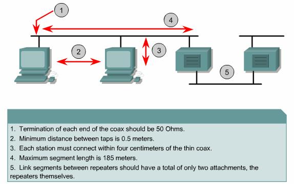
Figure
![]() illustrates a
configuration for an end-to-end collision domain with the maximum number of
segments and repeaters. Remember that only three segments can have stations
connected to them. The other two repeated segments are used to extend the
network.
illustrates a
configuration for an end-to-end collision domain with the maximum number of
segments and repeaters. Remember that only three segments can have stations
connected to them. The other two repeated segments are used to extend the
network.
The Lab Activity will help students decode a waveform.
The Interactive Media Activity will help students learn the features of 10BASE5 technology.
|
|
|
|
|||
|
|
|
|
This page covers 10BASE2, which was introduced in 1985.
Installation was easier because of its smaller size, lighter weight, and greater flexibility. 10BASE2 still exists in legacy networks. Like 10BASE5, it is no longer recommended for network installations. It has a low cost and does not require hubs.
10BASE2
also uses
10BASE2 has a stranded central conductor. Each of the maximum five segments of thin coaxial cable may be up to 185 m (607 ft) long and each station is connected directly to the BNC T-shaped connector on the coaxial cable.
Only one station can transmit at a time or a collision will occur. 10BASE2 also uses half-duplex. The maximum transmission rate of 10BASE2 is 10 Mbps.
There
may be up to 30 stations on a 10BASE2 segment. Only three out of five
consecutive segments between any two stations can be populated. ![]()
The Interactive Media Activity will help students learn the features of 10BASE2 technology.
|
|
|
|
This page covers 10BASE-T, which was introduced in 1990.
10BASE-T used cheaper and easier to install Category 3 UTP copper cable instead of coax cable. The cable plugged into a central connection device that contained the shared bus. This device was a hub. It was at the center of a set of cables that radiated out to the PCs like the spokes on a wheel. This is referred to as a star topology. As additional stars were added and the cable distances grew, this formed an extended star topology. Originally 10BASE-T was a half-duplex protocol, but full-duplex features were added later. The explosion in the popularity of Ethernet in the mid-to-late 1990s was when Ethernet came to dominate LAN technology.
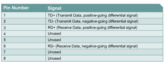
10BASE-T
also uses ![]() shows the pinout
arrangement for a 10BASE-T connection. The pair that transmits data on one
device is connected to the pair that receives data on the other device.
shows the pinout
arrangement for a 10BASE-T connection. The pair that transmits data on one
device is connected to the pair that receives data on the other device.
Half duplex or full duplex is a configuration choice. 10BASE-T carries 10 Mbps of traffic in half-duplex mode and 20 Mbps in full-duplex mode.
The Interactive Media Activity will help students learn the features of 10BASE-T technology.
|
|
|
|
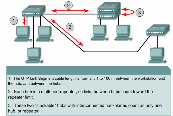
This page explains the wiring and architecture of 10BASE-T.
A 10BASE-T link generally connects a station to a hub or switch. Hubs are multi-port repeaters and count toward the limit on repeaters between distant stations. Hubs do not divide network segments into separate collision domains. Bridges and switches divide segments into separate collision domains. The maximum distance between bridges and switches is based on media limitations.
Although hubs may be linked, it is best to avoid this arrangement. A network with linked hubs may exceed the limit for maximum delay between stations. Multiple hubs should be arranged in hierarchical order like a tree structure. Performance is better if fewer repeaters are used between stations.
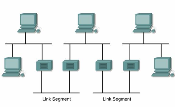
An
architectural example is shown in Figure ![]() . The distance from one end of the network to the other places the
architecture at its limit. The most important aspect to consider is how to keep
the delay between distant stations to a minimum, regardless of the architecture
and media types involved. A shorter maximum delay will provide better overall performance.
. The distance from one end of the network to the other places the
architecture at its limit. The most important aspect to consider is how to keep
the delay between distant stations to a minimum, regardless of the architecture
and media types involved. A shorter maximum delay will provide better overall performance.
10BASE-T links can have unrepeated distances of up to 100 m (328 ft). While this may seem like a long distance, it is typically maximized when wiring an actual building. Hubs can solve the distance issue but will allow collisions to propagate. The widespread introduction of switches has made the distance limitation less important. If workstations are located within 100 m (328 ft) of a switch, the 100-m distance starts over at the switch.
|
|
|
|
This page will discuss 100-Mbps Ethernet, which is also known as Fast Ethernet. The two technologies that have become important are 100BASE-TX, which is a copper UTP medium and 100BASE-FX, which is a multimode optical fiber medium.
Three
characteristics common to 100BASE-TX and 100BASE-FX are the timing parameters,
the frame format, and parts of the transmission process. 100BASE-TX and
100BASE-FX both share timing parameters. Note that one bit time at 100-Mbps =
10 ns = .01 microseconds = 1 100-millionth of a second. ![]()
The
100-Mbps frame format is the same as the 10-Mbps frame. ![]()
Fast Ethernet is ten times faster than 10BASE-T. The bits that are sent are shorter in duration and occur more frequently. These higher frequency signals are more susceptible to noise. In response to these issues, two separate encoding steps are used by 100-Mbps Ethernet. The first part of the encoding uses a technique called 4B/5B, the second part of the encoding is the actual line encoding specific to copper or fiber.
|
|
|
|
This page will describe 100BASE-TX.
In 1995, 100BASE-TX was the standard, using Category 5 UTP cable, which became commercially successful.
The original coaxial Ethernet used half-duplex transmission so only one device could transmit at a time. In 1997, Ethernet was expanded to include a full-duplex capability that allowed more than one PC on a network to transmit at the same time. Switches replaced hubs in many networks. These switches had full-duplex capabilities and could handle Ethernet frames quickly.
100BASE-TX
uses 4B/5B encoding, which is then scrambled and converted to Multi-Level
Transmit (MLT-3) encoding. Figure ![]() shows four
waveform examples. The top waveform has no transition in the center of the
timing window. No transition indicates a binary zero. The second waveform shows
a transition in the center of the timing window. A transition represents a
binary one. The third waveform shows an alternating binary sequence. The fourth
wavelength shows that signal changes indicate ones and horizontal lines
indicate zeros.
shows four
waveform examples. The top waveform has no transition in the center of the
timing window. No transition indicates a binary zero. The second waveform shows
a transition in the center of the timing window. A transition represents a
binary one. The third waveform shows an alternating binary sequence. The fourth
wavelength shows that signal changes indicate ones and horizontal lines
indicate zeros.
Figure
![]() shows the pinout
for a 100BASE-TX connection. Notice that the two separate transmit-receive
paths exist. This is identical to the 10BASE-T configuration.
shows the pinout
for a 100BASE-TX connection. Notice that the two separate transmit-receive
paths exist. This is identical to the 10BASE-T configuration.
100BASE-TX carries 100 Mbps of traffic in half-duplex mode. In full-duplex mode, 100BASE-TX can exchange 200 Mbps of traffic. The concept of full duplex will become more important as Ethernet speeds increase.
|
|
|
|
This page covers 100BASE-FX.
When copper-based Fast Ethernet was introduced, a fiber version was also desired. A fiber version could be used for backbone applications, connections between floors, buildings where copper is less desirable, and also in high-noise environments. 100BASE-FX was introduced to satisfy this desire. However, 100BASE-FX was never adopted successfully. This was due to the introduction of Gigabit Ethernet copper and fiber standards. Gigabit Ethernet standards are now the dominant technology for backbone installations, high-speed cross-connects, and general infrastructure needs.
The
timing, frame format, and transmission are the same in both versions of
100-Mbps Fast Ethernet. In Figure ![]() , the top waveform
has no transition, which indicates a binary 0. In the second waveform, the
transition in the center of the timing window indicates a binary 1. In the
third waveform, there is an alternating binary sequence. In the third and
fourth waveforms it is more obvious that no transition indicates a binary zero
and the presence of a transition is a binary one.
, the top waveform
has no transition, which indicates a binary 0. In the second waveform, the
transition in the center of the timing window indicates a binary 1. In the
third waveform, there is an alternating binary sequence. In the third and
fourth waveforms it is more obvious that no transition indicates a binary zero
and the presence of a transition is a binary one.
Figure
![]() summarizes a
100BASE-FX link and pinouts. A fiber pair with either ST or SC connectors is
most commonly used.
summarizes a
100BASE-FX link and pinouts. A fiber pair with either ST or SC connectors is
most commonly used.
The separate Transmit (Tx) and Receive (Rx) paths in 100BASE-FX optical fiber allow for 200-Mbps transmission.

|
|
|
|
This page describes the architecture of Fast Ethernet.
Fast Ethernet links generally consist of a connection between a station and a hub or switch. Hubs are considered multi-port repeaters and switches are considered multi-port bridges. These are subject to the 100-m (328 ft) UTP media distance limitation.
A Class I repeater may introduce up to 140 bit-times latency. Any repeater that changes between one Ethernet implementation and another is a Class I repeater. A Class II repeater is restricted to smaller timing delays, 92 bit times, because it immediately repeats the incoming signal to all other ports without a translation process. To achieve a smaller timing delay, Class II repeaters can only connect to segment types that use the same signaling technique.
As with 10-Mbps versions, it is possible to modify some of the architecture rules for 100-Mbps versions. Modification of the architecture rules is strongly discouraged for 100BASE-TX. 100BASE-TX cable between Class II repeaters may not exceed 5 m (16 ft). Links that operate in half duplex are not uncommon in Fast Ethernet. However, half duplex is undesirable because the signaling scheme is inherently full duplex.
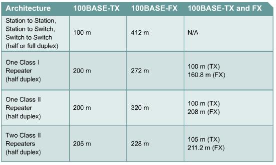
Figure
![]() shows architecture
configuration cable distances. 100BASE-TX links can have unrepeated distances
up to 100 m. Switches have made this distance limitation less important. Most
Fast Ethernet implementations are switched.
shows architecture
configuration cable distances. 100BASE-TX links can have unrepeated distances
up to 100 m. Switches have made this distance limitation less important. Most
Fast Ethernet implementations are switched.
This page concludes this lesson. The next lesson will discuss Gigabit and 10-Gigabit Ethernet. The first page describes 1000-Mbps Ethernet standards.
|
|
|
|
|||
|
|
|
|
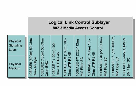
This
page covers the 1000-Mbps Ethernet or Gigabit Ethernet standards. These
standards specify both fiber and copper media for data transmissions. ![]() The
1000BASE-T standard, IEEE 802.3ab, uses Category 5, or higher, balanced copper
cabling. The 1000BASE-X standard, IEEE 802.3z, specifies 1 Gbps full duplex
over optical fiber.
The
1000BASE-T standard, IEEE 802.3ab, uses Category 5, or higher, balanced copper
cabling. The 1000BASE-X standard, IEEE 802.3z, specifies 1 Gbps full duplex
over optical fiber.
1000BASE-TX,
1000BASE-SX, and 1000BASE-LX use the same timing parameters, as shown in Figure ![]() . They use a 1 ns, 0.000000001 of a second, or 1 billionth of a second
bit time. The Gigabit Ethernet frame has the same format as is used for 10 and
100-Mbps Ethernet. Some implementations of Gigabit Ethernet may use different
processes to convert frames to bits on the cable. Figure
. They use a 1 ns, 0.000000001 of a second, or 1 billionth of a second
bit time. The Gigabit Ethernet frame has the same format as is used for 10 and
100-Mbps Ethernet. Some implementations of Gigabit Ethernet may use different
processes to convert frames to bits on the cable. Figure ![]() shows the Ethernet
frame fields.
shows the Ethernet
frame fields.
The differences between standard Ethernet, Fast Ethernet and Gigabit Ethernet occur at the physical layer. Due to the increased speeds of these newer standards, the shorter duration bit times require special considerations. Since the bits are introduced on the medium for a shorter duration and more often, timing is critical. This high-speed transmission requires higher frequencies. This causes the bits to be more susceptible to noise on copper media.
These issues require Gigabit Ethernet to use two separate encoding steps. Data transmission is more efficient when codes are used to represent the binary bit stream. The encoded data provides synchronization, efficient usage of bandwidth, and improved signal-to-noise ratio characteristics.
At the physical layer, the bit patterns from the MAC layer are converted into symbols. The symbols may also be control information such as start frame, end frame, and idle conditions on a link. The frame is coded into control symbols and data symbols to increase in network throughput.
Fiber-based Gigabit Ethernet, or 1000BASE-X, uses 8B/10B encoding, which is similar to the 4B/5B concept. This is followed by the simple nonreturn to zero (NRZ) line encoding of light on optical fiber. This encoding process is possible because the fiber medium can carry higher bandwidth signals.
|
|
|
|
This page will describe 1000BASE-T.
As Fast Ethernet was installed to increase bandwidth to workstations, this began to create bottlenecks upstream in the network. The 1000BASE-T standard, which is IEEE 802.3ab, was developed to provide additional bandwidth to help alleviate these bottlenecks. It provided more throughput for devices such as intra-building backbones, inter-switch links, server farms, and other wiring closet applications as well as connections for high-end workstations. Fast Ethernet was designed to function over Category 5 copper cable that passes the Category 5e test. Most installed Category 5 cable can pass the Category 5e certification if properly terminated. It is important for the 1000BASE-T standard to be interoperable with 10BASE-T and 100BASE-TX.
Since Category 5e cable can reliably carry up to 125 Mbps of traffic, 1000 Mbps or 1 Gigabit of bandwidth was a design challenge. The first step to accomplish 1000BASE-T is to use all four pairs of wires instead of the traditional two pairs of wires used by 10BASE-T and 100BASE-TX. This requires complex circuitry that allows full-duplex transmissions on the same wire pair. This provides 250 Mbps per pair. With all four-wire pairs, this provides the desired 1000 Mbps. Since the information travels simultaneously across the four paths, the circuitry has to divide frames at the transmitter and reassemble them at the receiver.
The 1000BASE-T encoding with 4D-PAM5 line encoding is used on Category 5e, or better, UTP. That means the transmission and reception of data happens in both directions on the same wire at the same time. As might be expected, this results in a permanent collision on the wire pairs. These collisions result in complex voltage patterns. With the complex integrated circuits using techniques such as echo cancellation, Layer 1 Forward Error Correction (FEC), and prudent selection of voltage levels, the system achieves the 1-Gigabit throughput.
In
idle periods there are nine voltage levels found on the cable, and during data
transmission periods there are 17 voltage levels found on the cable. ![]() With this large
number of states and the effects of noise, the signal on the wire looks more
analog than digital. Like analog, the system is more susceptible to noise due
to cable and termination problems.
With this large
number of states and the effects of noise, the signal on the wire looks more
analog than digital. Like analog, the system is more susceptible to noise due
to cable and termination problems.
The
data from the sending station is carefully divided into four parallel streams,
encoded, transmitted and detected in parallel, and then reassembled into one
received bit stream. Figure ![]() represents the
simultaneous full duplex on four-wire pairs. 1000BASE-T supports both
half-duplex as well as full-duplex operation. The use of full-duplex 1000BASE-T
is widespread.
represents the
simultaneous full duplex on four-wire pairs. 1000BASE-T supports both
half-duplex as well as full-duplex operation. The use of full-duplex 1000BASE-T
is widespread.
|
|
|
|
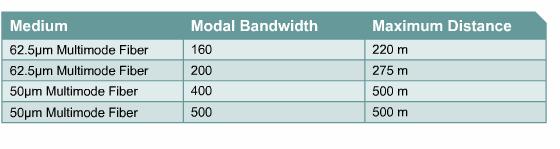
This page will discuss single-mode and multimode optical fiber.
The
IEEE 802.3 standard recommends that Gigabit Ethernet over fiber be the
preferred backbone technology. ![]()
The
timing, frame format, and transmission are common to all versions of 1000 Mbps.
Two signal-encoding schemes are defined at the physical layer. ![]() The 8B/10B scheme
is used for optical fiber and shielded copper media, and the pulse amplitude
modulation 5 (PAM5) is used for UTP.
The 8B/10B scheme
is used for optical fiber and shielded copper media, and the pulse amplitude
modulation 5 (PAM5) is used for UTP.
1000BASE-X uses 8B/10B encoding converted to non-return to zero (NRZ) line encoding. NRZ encoding relies on the signal level found in the timing window to determine the binary value for that bit period. Unlike most of the other encoding schemes described, this encoding system is level driven instead of edge driven. That is the determination of whether a bit is a zero or a one is made by the level of the signal rather than when the signal changes levels.
The NRZ signals are then pulsed into the fiber using either short-wavelength or long-wavelength light sources. The short-wavelength uses an 850 nm laser or LED source in multimode optical fiber (1000BASE-SX). It is the lower-cost of the options but has shorter distances. The long-wavelength 1310 nm laser source uses either single-mode or multimode optical fiber (1000BASE-LX). Laser sources used with single-mode fiber can achieve distances of up to 5000 meters. Because of the length of time to completely turn the LED or laser on and off each time, the light is pulsed using low and high power. A logic zero is represented by low power, and a logic one by high power.
The
Media Access Control method treats the link as point-to-point. Since separate
fibers are used for transmitting (Tx) and receiving
(Rx) the connection is inherently full duplex. Gigabit Ethernet permits only a
single repeater between two stations. Figure ![]() is a 1000BASE
Ethernet media comparison chart.
is a 1000BASE
Ethernet media comparison chart.
|
|
|
|
This page will discuss the architecture of Gigabit Ethernet.
The
distance limitations of full-duplex links are only limited by the medium, and
not the round-trip delay. Since most Gigabit Ethernet is switched, the values
in Figures ![]() and
and ![]() are the practical
limits between devices. Daisy-chaining, star, and extended star topologies are
all allowed. The issue then becomes one of logical topology and data flow, not
timing or distance limitations.
are the practical
limits between devices. Daisy-chaining, star, and extended star topologies are
all allowed. The issue then becomes one of logical topology and data flow, not
timing or distance limitations.
A 1000BASE-T UTP cable is the same as 10BASE-T and 100BASE-TX cable, except that link performance must meet the higher quality Category 5e or ISO Class D (2000) requirements.
Modification of the architecture rules is strongly discouraged for 1000BASE-T. At 100 meters, 1000BASE-T is operating close to the edge of the ability of the hardware to recover the transmitted signal. Any cabling problems or environmental noise could render an otherwise compliant cable inoperable even at distances that are within the specification.
It is recommended that all links between a station and a hub or switch be configured for Auto-Negotiation to permit the highest common performance. This will avoid accidental misconfiguration of the other required parameters for proper Gigabit Ethernet operation.
|
|
|
|
This page will describe 10-Gigabit Ethernet and compare it to other versions of Ethernet.
IEEE 802.3ae was adapted to include 10 Gbps full-duplex transmission over fiber optic cable. The basic similarities between 802.3ae and 802.3, the original Ethernet are remarkable. This 10-Gigabit Ethernet (10GbE) is evolving for not only LANs, but also MANs, and WANs.
With the frame format and other Ethernet Layer 2 specifications compatible with previous standards, 10GbE can provide increased bandwidth needs that are interoperable with existing network infrastructure.
A major conceptual change for Ethernet is emerging with 10GbE. Ethernet is traditionally thought of as a LAN technology, but 10GbE physical layer standards allow both an extension in distance to 40 km over single-mode fiber and compatibility with synchronous optical network (SONET) and synchronous digital hierarchy (SDH) networks. Operation at 40 km distance makes 10GbE a viable MAN technology. Compatibility with SONET/SDH networks operating up to OC-192 speeds (9.584640 Gbps) make 10GbE a viable WAN technology. 10GbE may also compete with ATM for certain applications.
To
summarize, how does 10GbE compare to other varieties of Ethernet? ![]()
The basic standard governing CSMA/CD is IEEE 802.3. An IEEE 802.3 supplement, entitled 802.3ae, governs the 10GbE family. As is typical for new technologies, a variety of implementations are being considered, including:
The
IEEE 802.3ae Task force and the 10-Gigabit Ethernet
10-Gbps Ethernet (IEEE 802.3ae) was standardized in June 2002. It is a full-duplex protocol that uses only optic fiber as a transmission medium. The maximum transmission distances depend on the type of fiber being used. When using single-mode fiber as the transmission medium, the maximum transmission distance is 40 kilometers (25 miles). Some discussions between IEEE members have begun that suggest the possibility of standards for 40, 80, and even 100-Gbps Ethernet.
|
|
|
|
This page describes the 10-Gigabit Ethernet architectures.
As with the development of Gigabit Ethernet, the increase in speed comes with extra requirements. The shorter bit time duration because of increased speed requires special considerations. For 10 GbE transmissions, each data bit duration is 0.1 nanosecond. This means there would be 1,000 GbE data bits in the same bit time as one data bit in a 10-Mbps Ethernet data stream. Because of the short duration of the 10 GbE data bit, it is often difficult to separate a data bit from noise. 10 GbE data transmissions rely on exact bit timing to separate the data from the effects of noise on the physical layer. This is the purpose of synchronization.
In response to these issues of synchronization, bandwidth, and Signal-to-Noise Ratio, 10-Gigabit Ethernet uses two separate encoding steps. By using codes to represent the user data, transmission is made more efficient. The encoded data provides synchronization, efficient usage of bandwidth, and improved Signal-to-Noise Ratio characteristics.
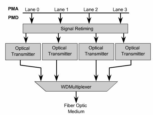
Complex serial bit streams are used for all versions of 10GbE except for 10GBASE-LX4, which uses Wide Wavelength Division Multiplex (WWDM) to multiplex four bit simultaneous bit streams as four wavelengths of light launched into the fiber at one time.
Figure
![]() represents the
particular case of using four slightly different wavelength,
laser sources. Upon receipt from the medium, the optical signal stream is
demultiplexed into four separate optical signal streams. The four optical
signal streams are then converted back into four electronic bit streams as they
travel in approximately the reverse process back up through the sublayers to
the MAC layer.
represents the
particular case of using four slightly different wavelength,
laser sources. Upon receipt from the medium, the optical signal stream is
demultiplexed into four separate optical signal streams. The four optical
signal streams are then converted back into four electronic bit streams as they
travel in approximately the reverse process back up through the sublayers to
the MAC layer.
Currently, most 10GbE products are in the form of modules, or line cards, for addition to high-end switches and routers. As the 10GbE technologies evolve, an increasing diversity of signaling components can be expected. As optical technologies evolve, improved transmitters and receivers will be incorporated into these products, taking further advantage of modularity. All 10GbE varieties use optical fiber media. Fiber types include 10µ single-mode Fiber, and 50µ and 62.5µ multimode fibers. A range of fiber attenuation and dispersion characteristics is supported, but they limit operating distances.
Even
though support is limited to fiber optic media, some of the maximum cable
lengths are surprisingly short. ![]() No repeater is
defined for 10-Gigabit Ethernet since half duplex is explicitly not supported.
No repeater is
defined for 10-Gigabit Ethernet since half duplex is explicitly not supported.
As with 10 Mbps, 100 Mbps and 1000 Mbps versions, it is possible to modify some of the architecture rules slightly. Possible architecture adjustments are related to signal loss and distortion along the medium. Due to dispersion of the signal and other issues the light pulse becomes undecipherable beyond certain distances.
|
|
|
|
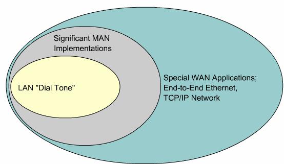
This page will teach students about the future of Ethernet.
Ethernet
has gone through an evolution from Legacy -> Fast -> Gigabit ->
MultiGigabit technologies. While other LAN technologies are still in place
(legacy installations), Ethernet dominates new LAN installations. So much so
that some have referred to Ethernet as the LAN "dial tone". Ethernet is now the
standard for horizontal, vertical, and inter-building connections. Recently
developing versions of Ethernet are blurring the distinction between LANs,
MANs, and WANs. ![]()
While
1-Gigabit Ethernet is now widely available and 10-Gigabit products becoming
more available, the IEEE and the 10-Gigabit Ethernet
Proposals for Ethernet arbitration schemes other than CSMA/CD have been made. The problem of collisions with physical bus topologies of 10BASE5 and 10BASE2 and 10BASE-T and 100BASE-TX hubs is no longer common. Using UTP and optical fiber with separate Tx and Rx paths, and the decreasing costs of switches make single shared media, half-duplex media connections much less important.
The future of networking media is three-fold:
Copper and wireless media have certain physical and practical limitations on the highest frequency signals that can be transmitted. This is not a limiting factor for optical fiber in the foreseeable future. The bandwidth limitations on optical fiber are extremely large and are not yet being threatened. In fiber systems, it is the electronics technology (such as emitters and detectors) and fiber manufacturing processes that most limit the speed. Upcoming developments in Ethernet are likely to be heavily weighted towards Laser light sources and single-mode optical fiber.
When Ethernet was slower, half-duplex, subject to collisions and a "democratic" process for prioritization, was not considered to have the Quality of Service (QoS) capabilities required to handle certain types of traffic. This included such things as IP telephony and video multicast.
The full-duplex high-speed Ethernet technologies that now dominate the market are proving to be sufficient at supporting even QoS-intensive applications. This makes the potential applications of Ethernet even wider. Ironically end-to-end QoS capability helped drive a push for ATM to the desktop and to the WAN in the mid-1990s, but now it is Ethernet, not ATM that is approaching this goal.
|
|
|
Summary |
This page summarizes the topics discussed in this module.
Ethernet is a technology that has increased in speed one thousand times, from 10 Mbps to 10,000 Mbps, in less than a decade. All forms of Ethernet share a similar frame structure and this leads to excellent interoperability. Most Ethernet copper connections are now switched full duplex, and the fastest copper-based Ethernet is 1000BASE-T, or Gigabit Ethernet. 10 Gigabit Ethernet and faster are exclusively optical fiber-based technologies.
10BASE5, 10BASE2, and 10BASE-T Ethernet are considered Legacy Ethernet. The four common features of Legacy Ethernet are timing parameters, frame format, transmission process, and a basic design rule.
Legacy
Ethernet encodes data on an electrical signal. The form of encoding used in 10
Mbps systems is called
In addition to a standard bit period, Ethernet standards set limits for slot time and interframe spacing. Different types of media can affect transmission timing and timing standards ensure interoperability. 10 Mbps Ethernet operates within the timing limits offered by a series of no more than five segments separated by no more than four repeaters.
A single thick coaxial cable was the first medium used for Ethernet. 10BASE2, using a thinner coax cable, was introduced in 1985. 10BASE-T, using twisted-pair copper wire, was introduced in 1990. Because it used multiple wires 10BASE-T offered the option of full-duplex signaling. 10BASE-T carries 10 Mbps of traffic in half-duplex mode and 20 Mbps in full-duplex mode.
10BASE-T links can have unrepeated distances up to 100 m. Beyond that network devices such as repeaters, hub, bridges and switches are used to extend the scope of the LAN. With the advent of switches, the 4-repeater rule is not so relevant. You can extend the LAN indefinitely by daisy-chaining switches. Each switch-to-switch connection, with maximum length of 100m, is essentially a point-to-point connection without the media contention or timing issues of using repeaters and hubs.
100-Mbps Ethernet, also known as Fast Ethernet, can be implemented using twisted-pair copper wire, as in 100BASE-TX, or fiber media, as in 100BASE-FX. 100 Mbps forms of Ethernet can transmit 200 Mbps in full duplex.
Because the higher frequency signals used in Fast Ethernet are more susceptible to noise, two separate encoding steps are used by 100-Mbps Ethernet to enhance signal integrity.
Gigabit Ethernet over copper wire is accomplished by the following:
On Gigabit Ethernet networks bit signals occur in one tenth of the time of 100 Mbps networks and 1/100 of the time of 10 Mbps networks. With signals occurring in less time the bits become more susceptible to noise. The issue becomes how fast the network adapter or interface can change voltage levels to signal bits and still be detected reliably one hundred meters away at the receiving NIC or interface. At this speed encoding and decoding data becomes even more complex.
The fiber versions of Gigabit Ethernet, 1000BASE-SX and 1000BASE-LX offer the following advantages: noise immunity, small size, and increased unrepeated distances and bandwidth. The IEEE 802.3 standard recommends that Gigabit Ethernet over fiber be the preferred backbone technology.
|
