|
|
|
|
|
|
|
|
|
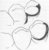
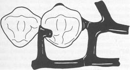
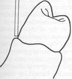
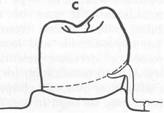
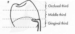
Fig. 7-31 Back-action circumferential clasp used on premolar abutment anterior to edentulous space. |
|
Chapter |
|
Direct retainers |
|
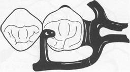
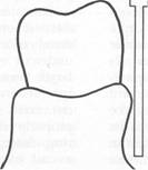
Fig. 7-30 Ring clasp may be used in reverse on abutment located anterior to tooth-bound edentulous space. |
|
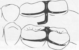
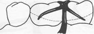
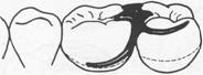
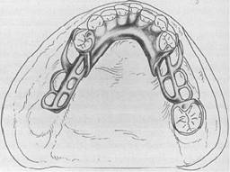
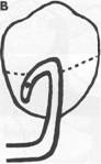
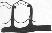
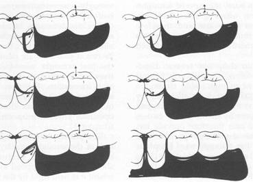
Fig.7-32 Embrasure clasp used where no edentulous space exists. Although in this drawing both retentive clasp arms are located on buccal surface and nonretentive arms on lingual surface, retention and reciprocation can be reversed on both teeth or on either tooth, depending on respective contours of the teeth. However, if second molar is sound and suitable stabilizing and retentive areas can be found, circum ferential clasp originating on distal surface of abutment is preferable. |
|
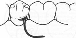
tive areas are available or when multiple restorations are justified, clasping can be accomplished by means of an embrasure clasp (Figs. 7-32 and 7-33). Sufficient space must be provided between the abutment teeth in their occlusal third to make room for the common body of the embrasure clasp (Fig. 7-34), yet the contact area should not be eliminated entirely. Historically, this clasp assembly demonstrates a high percentage of fracture caused by inadequate tooth preparation in the contact area. Because vulnerable areas of the teeth are involved, abutment protection with inlays or crowns is recommended. The decision to use unprotected abutments must be made at the time of oral examination and should be based on the patient's age, caries index, and oral hygiene, as well as on whether existing tooth contours are favorable or can be made favorable by tooth modification. Preparation of adjacent, contacting, uncrowned abutments to receive any type |
|
connector and should never be supported by a clasp arm alone. If the occlusal rest is part of a flexible assembly, it canI ).ot function adequately as an occlusal rest. Embrasure clasp In the fabrication of an unmodified Class II or Class III partial denture, there are no edentulous spaces on the opposite side of the arch to aid in clasping. Mechanically, this is a disadvantage. However, when the teeth are sound and reten |
|
|
|
|
|
|
|
McCracken's removable partial prosthodontics |
|
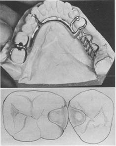
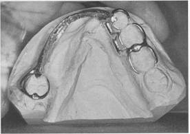
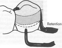
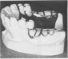
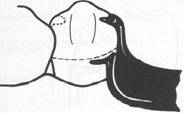
Fig. 7-33 Multiple clasping in surgically mutilated mouth. On the right are embrasure clasp, bar clasp arm, and conventional circumferential clasp engaging lingual undercuts on three abutment teeth. On the left is well-designed ring clasp engaging lingual undercut, with supporting strut on buccal surface and auxiliary occlusal rest to prevent mesial tipping. Note rigid design of major connector. |
|
|
|
A |
|
B |
|
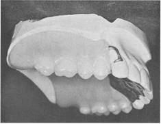
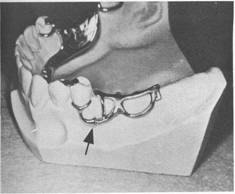
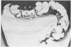
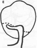
Fig. 7-35 A, Example of use of embrasure clasp for a Class II partially edentulous arch. Embrasure clasp on two left molar abutments was used in the absence of posterior modification space. B, Occlusal and proximal surfaces of adjacent molar and premolar prepared for embrasure clasp. Note that rest seat preparations are extended both buccally and lingually to accommodate retentive and reciprocal clasp arms. Adequate preparation confined to enamel can rarely be accomplished for such a clasp, especially when clasped teeth are opposed by natural teeth. |
|
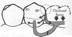
proximal shoulders can be established (Fig. 7-35). This is done to avoid interproximal wedging by the prosthesis, which could cause separation of the abutment teeth and result in food impaction and clasp displacement. In addition to providing support, occlusal rests also serve to shunt food away from contact areas. For this reason, occlusal rests should always be used whenever food impaction is possible. Embrasure clasps should have two retentive clasp arms and two reciprocal clasp arms, either bilaterally or diagonally opposed. An auxiliary occlusal rest or a bar clasp arm can be substituted for a circumferential reciprocal arm as long as definite reciprocation and stabilization result. |
|
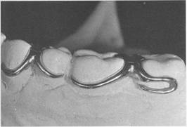
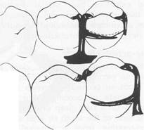
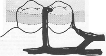
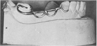
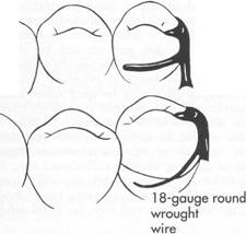
Fig. 7-34 Embrasure and hairpin circumferential retentive clasp arms. The terminus of each engages suitable retentive undercut. Use of hairpin-type clasp on second molar is made necessary by the fact that the only available undercut li_s directly below point of origin of clasp arm. of embrasure clasp of adequate interproximal bulk is difficult, especially when opposed by natural teeth. The embrasure clasp always should be used with double occlusal rests, even when definite |
|
|
|
|
|
|
|
|
|
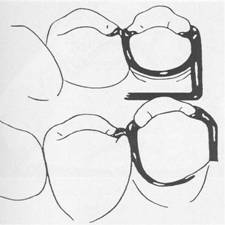
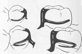
Fig. 7-37 Multiple clasp is actually two opposing circumferential clasps joined at terminal end of two reciprocal arms (mirror view). |
|
Lingual |
|
Buccl |
|
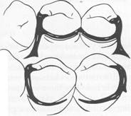
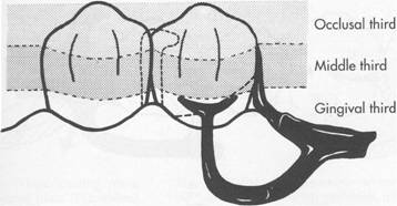
Fig. 7-36 Improper application of embrasure clasp design (mirror view). Failure to locate retentive and reciprocating-stabilizing arms in most advantageous positions (proper third of crowns) is quite evident. |
|
f |
|
" |
|
A lingually placed retentive bar clasp arm may be substituted if a rigid circumferential clasp arm is placed on the buccal surface for reciprocation, provided lingual retention is used on the opposite side of the arch. Common errors in the design of embrasure-type clasps a 24124l116y re illustrated in Fig. 7-36. Other less commonly used modifications of the cast circumferential clasp are the multiple clasp, the half-and-half clasp, and the reverseaction clasp. |
|
Chapter 7 |
|
Direct retainers |
|
|
|
"-- |
|
Fig. 7-38 Half-and-half clasp consists of one circum ferential retentive arm arising from distal aspect and a second circumferential arm arising from mesial aspect on the opposite side, with or without secondary occlusal rest. Broken line illustrates nonretentive reciprocal clasp arm used without secondary occlusal rest (mirror view). |
|
Multiple clasp The multiple clasp is simply two opposing circumferential clasps joined at the terminal end of the two reciprocal arms (Fig. 7-37). It is used when additional retention and stabilization are needed, usually on tooth-supported partial dentures. It may be used for multiple clasping in instances in which the partial denture replaces an entire half of the dental arch. It may be used rather than an embrasure clasp when the only available retentive areas are adjacent to each other. Its disadvantage is that two embrasure approaches are necessary rather than a single common embrasure for both clasps. Half-and-half clasp The half-and-half clasp consists of a circumferential retentive arm arising from one direction and a reciprocal arm arising from another (Fig. 7-38). The second arm must arise from a second minor connector, and this arm is used with or without an auxiliary occlusal rest. Reciprocation arising from a second minor connector can usually be accomplished with a short bar or with an auxiliary occlusal rest, thereby avoiding |
|
|
|
|
|
McCracken's removable partial prosthodontics |
|
so much tooth coverage. There is little justification for the use of the half-and-half clasp in bilateral extension base partial dentures. Its design was originally intended to provide dual retention, a principle that should be applied only to unilateral partial denture design. |
|
Reverse-action clasp The reverse-action, or hairpin, clasp arm is designed to permit engaging a proximal undercut from an occlusal approach (Fig. 7-39). Other methods of accomplishing the same result are with a ring clasp originating on the opposite side of the tooth or with a bar clasp arm originating from a gingival direction. However, when a proximal undercut must be used on a posterior abutment and when tissue undercuts, tilted teeth, or high tissue attachments prevent the use of a bar clasp arm, the reverse-action clasp may be used successfully. Although the ring clasp may be preferable, lingual undercuts may prevent the placement of a supporting strut withCmt tongue interference. In this limited situation the hairpin clasp arm serves adequately, despite its several disadvantages. The clasp covers considerable tooth surface and may trap debris; its occlu sal origin may increase the functional load on the tooth, and its flexibility is limited. Esthetics usually need not be considered when the clasp is used on a posterior abutment, but the hairpin clasp arm does have the additional disadvantage of displaying too much metal for use on an anterior abutment. Properly designed, the reverse-action clasp should make a hairpin turn to engage an undercut below the point of origin (see Fig. 7-39). The upper part of the arm of this clasp should be considered a minor connector, giving rise to the tapered loV\(er part of the arm. Therefore only the lower part of the arm should be flexible; with the retentive portion beginning beyond the turn, only the lower part of the arm should flex over the height of contour to engage a retentive undercut. The bend that connects the upper and lower parts of the arm should be rounded to prevent stress accumulation and fracture of the arm at the bend. The clasp should be designed and fabricated with this in mind. |
|
Fig. 7-39 Reverse-action, or hairpin, clasp arm may be used on abutments of tooth-supported dentures when proximal undercut lies below point of origin of clasp (mirror view), It may be esthetically objectionable and covers considerable tooth surface. It should be used only when a bar-type retentive arm is contraindicated because of a tissue undercut, tilted tooth, or shallow vestibule. |
|
These are the various types of cast circumferential clasps. As mentioned previously, they may be used in combination with bar clasp arms as long as differentiation between retention and reciprocation is made by their form and location. Circumferential and bar clasp arms may be made either flexible (retentive) or rigid (reciprocal) in any combination as long as each retentive clasp arm is opposed by a rigid reciprocal component. The use of many of the less desirable clasp forms can. be avoided by changing the crown forms of the abutments by tooth modification within the enamel or with restorations. In fabricating abutment coverage, tooth contours should be established that will permit the use of the most desirable clasp forms rather than a form that makes it necessary to use a less desirable clasp design. This is best accomplished by first altering the crown contour of abutment teeth not designated for restoration to meet the -requirements of guiding planes and survey line location. This is followed by the prescribed crown preparations. Before tooth reduction for |
|
|
|
Support |
|
Stabilization |
|
Retention |
|
Chapter 7 |
|
Direct retainers |
|
|
|
Buccal |
|
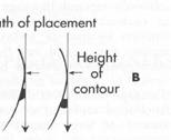
Fig. 7-40 Only one terminal of retentive arm engages undercut in gingival third of abutment. Suprabulge portion of retentive clasp arm provides only limited stabilization and may be eliminated. |
|
the prescribed crown preparations the requirements of guiding planes and survey line location should be met. |
|
Bar clasp The term bar clasp is generally preferred over the less descriptive term Roach clasp arm. Reduced to its simplest term, the bar clasp arm arises from the denture framework or a metal base and approaches the retentive undercut from a gingival direction (see Fig. 7-23). The bar clasp arm has been classified by the shape of the retentive terminal. Thus it has betfn identified as a T, modified T, I, or Y. The form the terminal takes is of little significance as long as it is mechanically and functionally effective, covers as little tooth surface as possible, and displays as little metal as possible. The T and Y clasp arms are the most frequently misused. It is unlikely that the full area of a T or Y terminal is ever necessary for adequate clasp retention. Although the larger area of contact would provide greater frictional resistance, this is not true clasp retention, and only that portion engaging an undercut area should be considered retentive. Only one terminal of such a clasp arm should be placed in an undercut area (Fig. 7-40). The remainder of the |
|
clasp arm may be superfluous unless it is needed as part of the clasp assembly to encircle the abutment tooth more than 180 degrees of its greatest circumference. If the bar clasp arm is made to be flexible for retentive purposes, any portion of the clasp above the height of contour will provide only limited stabilization, because it is also part of the flexible arm. Therefore in many instances this suprabulge portion of a T or Y clasp arm may be dispensed with, and the retentive terminal of the bar clasp should be designed to be biologically and mechanically sound rather than to conform to any alphabetical configuration. A current concept of bar clasp design is the RPI system (rest, proximal plate, I-bar). Basically, this clasp assembly consists of a mesioocclusal rest with the minor connector placed into the mesiolingual embrasure, but not contacting the adjacent tooth (Fig. 7-41, A). A distal guiding plane, extending from the marginal ridge to the junction of the middle and gingival thirds of the abutment tooth, is prepared to receive a proximal plate (Fig. 7-41, B). The buccolingual width of the guiding plane is determined by the proximal contour of the tooth (Fig. 7-41, A and C). The proximal plate, in conjunction with the minor connector supporting the rest, provides the stabilizing and reciprocal aspects of the clasp assembly. The I-bar |
|
|
|
|
|
|
|
|
|
|
|
McCracken's removable partial prosthodontics |
|
A |
|
Support |
|
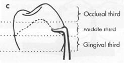
Occlusal third |
|
|
|
Stabilization |
|
Middle third |
|
B |
|
Retention |
|
Gingival third |
|
lingual |
|
c |
|
Support |
|
Stabilization |
|
D |
|
Buccal |
|
Fig. 7-41 Bar-type clasp assembly. A, Occlusal view. Component parts (proximal plate minor connector, rest with minor connector, and retentive arm) tripod abutment to prevent its migration. H, Proximal plate minor connector extends just far enough lingually so that together with mesial minor connector lingual migration of abutment is prevented. C, On narrow or tapered abutments (mandibular first premolars), proximal plate should be designed to be as narrow as possible but still sufficiently wide to prevent lingual migration. D, I-bar retainer located at greatest prominence of tooth in gingival third. |
|
|
|
|
|
|
|
|
|
|
|
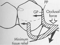
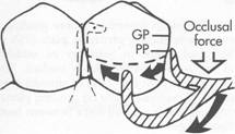
Fig. 7.42 Bar clasp assembly where guiding plane (GF) and corresponding proximal plate (PP) extend entire length of proximal tooth surface. Physiologic relief is required to prevent impingement of gingival tissues during function. Extending proximal plate to contact greater surface area of guide plane directs functional forces in horizontal direction, thus tooth (teeth) are loaded more than edentulous ridge. |
|
should be located in the gingival third of the buccal or labial surface of .the abutment in O.O1-inch undercut (Fig. 7-41, D). The whole arm of the I-bar should be tapered to its terminus, with no more than 2 mm of its tip contacting the abutment. The horizontal portion of the approach arm must be located at least 4 mm from the gingival margin and even more if possible. There are three basic approaches to the application of the RPI system. The location of the rest, the design of the minor connector (proximal plate) as it relates to the guiding plane, and the location of the retentive arm are factors that influence how this clasp system functions. Variations in these factors provide the basis for the differences among these approaches. All advocate the use of a rest located mesially on the primary abutment tooth adjacent to the extension base area. One approach recommends that the guiding plane and corresponding proximal plate minor connector extend the entire length of the proximal tooth surface, with physiologic tissue relief to eliminate impingement of the free gingival margin (Fig. 7-42). A second approach suggests that the guiding plane and corresponding proximal plate minor connector extend from the marginal ridge to the junction of the middle and gingival thirds of the proximal tooth surface (Fig. 7-43). Both |
|
Chapter 7 |
|
Direct retainers |
|
|
|
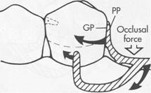
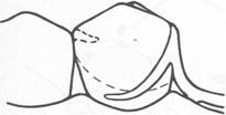
Fig. 7-43 Bar clasp assembly where guiding plane (ep) and corresponding proximal plate (PP) extend from marginal ridge to junction of middle and gingival thirds of proximal tooth surface. This decrease (compared with Fig. 7-42) in amount of surface area contact of proximal plate on guiding plane-more evenly distributes functional force between tooth and edentulous ridge. |
|
B |
|
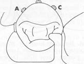
Fig. 7-44 Occlusal view of RPI bar clasp assembly. Placement of I-bar in O.OI-inch undercut: A, on distobuccal surface; B, at greatest mesiodistal prominence; and C, on mesiobuccal surface. |
|
approaches recommend that the retaining clasp arm be located in the gingival third of the buccal or labial surface of the abutment in a O.O1-inch undercut. Placement of the retaining clasp arm is generally in an undercut located at the greatest mesiodistal prominence of the tooth or adjacent to the extension base area (Fig. 7-44, A and B). The third approach favors a proximal plate minor connector that contacts approximately 1 mm of the gingival portion of the guiding plane (Fig. 7-45, A) and a retentive clasp arm located in a O.O1-inch undercut in the |
|
|
|
|
|
|
|
|
|
|
|
McCracken's removable partial prosthodontics |
|
A |
|
B |
|
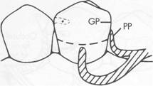
Fig. 7-45 A, Bar clasp assembly where proximal plate (PP) contacts approximately 1 mm of gingival portion of guiding plane (GP). During function, proximal plate and I-bar clasp arm are designed to move in mesiogingival direction, disengaging tooth. Lack of sustained contact between proximal plate and guiding plane distributes more functional force to edentulous ridge. Asterisk (*) indicates center of rotation. B, Modification of RPI system (_A clasp) is indicated when bar-type clasp is contraindicated and desirable undercut is located in gingival third of tooth away from extension base area. |
|
gingival third of the tooth at the greatest prominence or to the mesial away from the edentulous area (see Fig. 7-44, C). If the abutment teeth demonstrate contraindications for a bar-type clasp (that is, exaggerated buccal or lingual tilts, severe tissue undercut, or a shallow buccal vestibule) and the desirable undercut is located in the gingival third of the tooth away from the extension base area, a modification of the RPI |
|
Fig. 7-46 Bar clasp arm properly used on terminal abutment. Mesial extension of T is neither advantageous nor desirable in this situation &cause abutment tooth was encompassed more than 180 degrees. |
|
system (the RPA clasp) should be considered (Fig. 7-45, B). Application of each approach is predicated on the distribution of load to be applied to the tooth and edentulous ridge. In most situations the bar clasp arm can be used with tooth-supported partial dentures, with tooth-supported modification areas, or when an undercut that can be logically approached with a bar clasp arm lies on the side of an abutment tooth adjacent to a distal extension base (Figs. 7-46 through 7-50). If a tissue undercut prevents the use of a bar clasp arm, a mesially originating ring clasp, a cast, or a wrought-wire clasp or reverse-action clasp may be used. Preparation of adjacent abutments (natural teeth) to receive any type of interproximal direct retainer, traversing from lingual to buccal surfaces, is most difficult to adequately accomplish. Inevitably the relative size of the occlusal table is increased, contributing to undesirable and additional functional loading. The bar clasp arm is not a particularly flexible clasp arm because of the effects of its half-round form and its several planes of origin. Although the cast circumferential clasp arm can be made more flexible than can the bar clasp arm, the combination clasp is preferred for use on terminal abutments when torque and tipping are possible because of engaging an undercut |
|
|
|
|
|
Fig. 7-47 Bar clasp arm on distal abutment must be made light enough to be flexible and may be used only when it can engage proximal undercut adjacent to extension base. Mesial T-portion of clasp arm had to be placed to encompass abutment by more than degrees. It is placed on height of contour. Note finishing line (arrow) where clasp and denture base will join. |
|
away from the distal extension base. Situations often exist, however, in which a bar clasp arm may be used to advantage without jeopardizing a terminal abutment. A bar clasp arm swinging distally into the undercut may be a logical choice, since movement of the clasp on the abutment as the distal extension base moves tissueward is minimized by the distal location of the clasp terminal. The specific indications for using a bar clasp arm are (1) when a small degree of undercut (0.01 inch) exists in the cervical third of the abutment tooth, which may be approached from a gingival direction; (2) on abutment teeth for tooth-supported partial dentures or toothsupported modification areas (Fig. 7-51); (3) in distal extension base situations; and (4) in situations in which esthetic considerations must be accommodated and a cast clasp is indicated. Thus use of the bar clasp arm is contraindicated when a deep cervical undercut exists or when a severe tooth and/or tissue undercut exists, either of which must be bridged by excessive blockout. When severe tooth and tissue undercuts exist, a bar clasp arm usually is an annoyance to the tongue and cheek and also traps food debris. |
|
Chapter 7 |
|
Direct retainers |
|
|
|
Fig. 7-48 Bar clasp arm on maxillary terminal abutment. Note uniform taper from point where it will emerge from resin base and that it engages tooth undercut on side adjacent to distal extlmsion base. Butt-type joint for finishing line between direct retainer and acrylic resin base is provided. |
|
Other limiting factors in the selection of a bar clasp assembly include a shallow vestibule or an excessive buccal or lingual tilt of the abutment tooth (Fig. 7-52). Some common errors in the design of bar-type clasps are illustrated in Fig. 7-53. There are several other types of bar clasps, one of which is the infrabulge clasp. It is designed so that the bar arm arises from the border of the denture base, either as an extension of a cast base or attached to the border of a resin base (Fig. 7-54). It is made more flexible than the usual bar clasp arm in that the portion of the cast base that gives rise to the clasp arm is separated from the clasp arm itself, either by a saw cut or by being cast against a separating shim of matrix metal, which is later removed with acid. It may be made more flexible through the use of wrought wire, which is attached to a metal base by soldering or is embedded in the border of a resin base. Some of the advantages attributed to the infrabulge clasp are (1) its interproximallocation, which may be used to esthetic advantage; (2) increased retention without tipping action on the abutment; and (3) less chance of accidental distortion resulting from its proximity to the denture border. The wearer .should be meticulous in the care of a denture so made, not only |
|
|
|
|
|
|
|
|
|
McCracken's removable partial prosthodontics |
|
Fig. 7-49 Bar clasp arm on lower molar abutment engaging mesiobuccal undercut. Note proper use of parallel proximal guiding planes. |
|
Fig. 7-50 Bar clasps used for both retention and reciprocation. Bar-type retainer on right second premolar engages distobuccal undercut. Bar-type configuration on lingual aspect of left molar is used for stabilization and reciprocation and does not engage undercut. |
|
for reasons of oral. hygiene but also to prevent cariogenic debris from being held against tooth surfaces. |
|
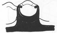
Combination clasp The combination clasp consists of a wroughtwire retentive clasp arm and a cast reciprocal clasp arm (Fig. 7-55). Although the latter may be in the form of a.bardasp arm, it is llsuallya |
|
Fig. 7-51 Bar retainer is used on anterior abutment of modification space, and its terminus engages distobuccal undercut. Denture is designed to rotate around terminal abutments when force is directed toward basal seat on left. Such.rotation vvould impart force on right premolar directed superiorly and anteriorly. However, this direction of force is resisted in great part by mesial contact with canine. Direct retainer on right premolar engaging mesiobuccal undercut would tend to force tooth superiorly and posteriorly. |
|
circumferential arm. The retentive arm is almost always circumferential, but it also may be used in the manner of a bar, originating gingivally from the denture base. The advantages of the combination clasp lie . in. the £Iexibility, the .adjustability, and the |
|
|
|
|
|
|
|
|
|
|
|
|
|
|
|
|
|
|
|
A |
|
Chapter 7 |
|
Direct retainers |
|
|
|
B |
|
Fig. 7-52 Contraindications for selection of bar-type clasps. A, Severe buccal or lingual tilts of abutment teeth. H, Severe tissue undercuts. C, Shallow buccal or labial vestibules. |
|
" |
|
c |
|
I |
|
A |
|
F |
|
Fig. 7-53 Common errors and recommended corrections in design of bar-type clasp assemblies. A, Survey line is unsuitable for bar clasp (too high). H, Retentive portion of bar clasp arm improperly contoured to resist dislodging force in occlusal direction. C, Retentive tip not located in gingival third of abutment. D, Contour of abutment correctly altered to receive bar clasp. E and F, Correct position of bar clasp assembly. |
|
|
|
|
|
|
|
|
|
|
|
McCracken's removable partial prosthodontics |
|
appearance of the wrought-wire retentive arm. It is used when maximum flexibility is desirable, such as on an abutment tooth adjacent to a distal extension base or on a weak abutment when a bar-type direct retainer is contraindicated. It may be used for its adjustability when precise retentive requirements are unpredictable and later adjustment to increase or decrease retention may be necessary. A third justification for its use is its esthetic advantage over cast clasps. Wrought in structure, it may be used in smaller diameters than a cast clasp, with less danger of fracture. Because it is round, light is reflected in such a manner that the display of metal is less |
|
A |
|
Lingual |
|
c |
|
Buccal |
|
noticeable than with the broader surfaces of a cast clasp. The most common use of the combination clasp is on an abutment tooth adjacent to a distal extension base where only a mesial undercut exists on the abutment or where a large tissue undercut contraindicates a bartype retainer (Fig. 7-56). When a distal undercut exists that may be approached with a properly designed bar clasp arm or with a ring clasp (despite its several disadvantages), a cast clasp can be located so that it will not cause abutment tipping as the distal extension base moves tissueward. When the undercut is on the side of the abutment away |
|
" |
|
B |
|
Lingual |
|
D |
|
Buccal |
|
Fig. 7-54 Infrabulge clasp designed by M.M. DeVan (mirror view), A and B, 'Lirigual ai!ped may be open or plated. DeVan recommended that two occlusal rests be used on each abutment. C, Clasp arm arises from border of metal base and is separated by saw cut or by having been cast agairist a metal shim, which is later removed. Wrought-wire retentive arm may be soldered to metal base to accomplish same purpose. D, Clasp arm is attached to buccal flange of acrylic resin denture base with autopolymerizing acrylic resiri. This is usually a wrought-wire arm. |
|
|
|
|
|
from the extension base, the tapered wroughtwire retentive arm offers greater flexibility than does the cast clasp arm and therefore better dissipates functional stresses. For this reason the combination clasp is preferred (Fig. 7-56, D). The combination clasp has several disadvantages: (1) it involves extra steps in fabrication, particularly when high-fusing chromium alloys are used; (2) it may be distorted by careless handling on the part of the patient; and (3), because it is bent by hand, it may be less accurately adapted and therefore provide less stabilization in the suprabulge portion. The disadvantages of the wrought-wire clasp are offset by its several advantages, which are (1) its flexibility; (2) its adjustability; (3) its esthetic advantage over other retentive circumferential clasp arms; (4) that a minimum of tooth surface is covered because of its line contact with the tooth, rather than having the surface contact of a cast clasp arm; and (5) that fatigue failures in service are less likely to occur with the tapered |
|
A |
|
Chapter 7 |
|
Direct retainers |
|
|
|
wrought-wire retentive arm than with the cast, half-round retentive arm. The disadvantages listed previously should not prevent its use regardless of the type of alloy being used for the cast framework. Technical problems are minimized by selecting the best wrought wire for this purpose and then either casting to it or soldering it to the cast framework. Selection of wrought wire, attachment of it to the framework, and subsequent laboratory procedures to maintain its optimum physical properties are presented in Chapter 12. The patient may be taught to avoid distortion of the wrought wire by explaining that to remove the partial dentures, the fingernail should always be applied to its point of origin, where it is held rigid by the casting, rather than to the flexible terminal end. Often, lingual retention may be used rather than buccal retention, especially on a mandibular abutment, so that the wrought-wir_ arm is never touched by the patient during removal of the denture. |
|
Fig. 7-55 A, Combination clasp consists of cast reciprocal arm and tapered, round wrought-wire retentive clasp arm. The latter is either cast to, or soldered to, a cast framework. This design is recommended for anterior abutment of posterior modification space in Class II partially edentulous arch, where only a mesiobuccal undercut exists, to minimize the effects of first-class lever system. B, In addition to advantages of flexibility, adjustability, and appearance, wrought-wire retentive arm makes only line contact with abutment tooth, rather than broader contact of cast clasp. |
|
|
|
|
|
McCracken's removable partial prosthodontics |
|
A |
|
c |
|
E |
|
B |
|
D |
|
F |
|
Fig. 7-56 Five types of extracoronal direct retainer assemblies that may be usee! on abutments adjacent to distal extension base to avoid or minimize the effects of cantilever design. Arrows indicate general direction of movement of retentive tips of retainer arms when cl.enture base rotates toward and away from edentulous ridge. A, Distobuccal undercut engaged by one-half T-type bar clasp. Portion of clasp arm on and above height of contour might afford some stabilization against horizontal rotation of denture base. B, I-bar placed in undercut at middle (anteroposteriorly) of buccal surface. This retainer contacts tooth only at its tip. Note that guiding plane on distal aspect of abutment is contacted by metal of denture framework and that mesial rest is used. C, Interproximal ring clasp engaging distobuccal undercut. Bar-type retainer cannot be used because of tissue undercuts inferior to buccal surface of abutment. D, Round, uniformly tapered IS-gauge wrought-wire circumferential retainer arm engaging mesiobuccal undercut. A wrought-wire arm, instead of a cast arm, should be used in this situation because of ability of wrought wire to flex omnidirectionally. Cast half-round retainer arm would not flex edgewise, which could result in excessive stress on tooth when rotation of denture base occurs. E, Hairpin clasp may be used when undercut lies cervical to origin of retainer arm. Both hairpin and interproximal ring clasps may be used to engage distobuccal undercut on terminal abutment of distal extension denture. However, distobuccal undercut on terminal abutment should be engaged by bar-type clasp in the absence of large buccal tissue undercut cervical to terminal abutment. Hairpin and interproximal ring clasps are least desirable of clasping situations illustrated here. F, Lingual view shows use of double occlusal rests, connected to lingual bar by minor connector in illustrated designs. This design eliminates need for lingual clasp arm, places fulcrum line anteriorly to make better use of residual ridge for support, and provides stabilization against horizontal rotation of denture base. |
|
Instead, removal may be accomplished by lifting against the cast reciprocal arm located on the buccal side of the tooth. This may negate the esthetic advantage of the wrought-wire clasp arm, and esthetics should be given |
|
preference when the choice must be made between buccal and lingual retention. In most situations, however, retention must be used where it is possible to create it and the clasp designed accordingly. |
|
|
|
A |
|
B |
|
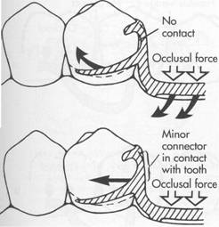
Fig. 7-57 A, Minor connector supporting distal rest does not contact prepared guiding plane, resulting in uncontrolled stress to abutment tooth. B, Minor connector contacts prepared guiding plane and directs stresses around arch through proximal contacts. |
|
Lingual retention in conjunction with internal rests The internal rest is covered in Chapter 6. It is emphasized that the internal rest is not used as a retainer but that its near-vertical walls provide for reciprocation against a lingually placed retentive clasp arm. For this reason, visible clasp arms may be eliminated, thus avoiding one of the principal objections to the extracoronal retainer. Such a retentive clasp arm, terminating in an existing or prepared infrabulge area on the abutment tooth, may be of any accept able design. It is usually a circumferential arm arising from the body of the denture framework at the rest area. It should be wrought, because the advantages of adjustabil ity and flexibility make the wrought clasp arm preferable. It may be cast with gold or low-fusing chromium-cobalt alloy, or it may be assembled by being soldered to one of the higher-fusing chromium-cobalt alloys. In |
|
Chapter 7 |
|
Direct retainers |
|
|
|
any event, future adjustment or repair is facilitated. The use of lingual extracoronal retention avoids much of the cost of the internal attachment yet disposes of a visible clasp arm when esthetics must be considered. Often it is employed with a tooth-supported partial denture only on the anterior abutments and, when esthetics is not a consideration, the posterior abutments are clasped in the conventional manner (see Fig. 6-13). One of the dentist's prime considerations in clasp selection is the control of stress transferred to the abutment teeth when the patient exerts an occluding force on the artificial teeth. The location and design of rests, the clasp arms, and the position of minor connectors as they relate to guiding planes are key factors in controlling transfer of stress to abutments. Errors in the design of a clasp assembly can result in uncOntrolled stress to abutment teeth and their supporting tissues. Some common errors and their corrections are illustrated in Figs. 7-57 and 7-58. The choice of clasp designs should be based on biologic as well as mechanical principles. The dentist responsible for the treatment being rendered must be able to justify the clasp design used for each abutment tooth in keeping with these principles. |
|
OTHER TYPES OF RETAINERS |
|
Numerous other types of retainers for partial dentures have been devised that cannot be classified as being primarily of the intracoronal or extracoronal type. Neither can they be classified as relying primarily on frictional resistance or placement of an element in an undercut to prevent displacement of the denture. However, all of these use some type of locking device, located either intracoronally or extracoronally, for providing retention without visible clasp retention. Although the motivation behind the development of other types of retainers has usually been a desire to eliminate visible clasp retainers, the desire to minimize torque and tipping stresses on the abutment teeth has also been given consideration. |
|
|
|
|
|
|
|
|
|
|
|
McCracken's removable partial prosthodontics |
|
A |
|
_ c |
|
D |
|
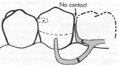
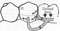
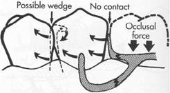
" Fig. 7-58 A, Clasp assembly designed so that vertical occlusal force results in proximal plate moving cendcally and out of contact with guiding plane as illustrated in B. This lack of contact may contribute to possible wedging effect. C, Extending contact of proximal plate on prepared guiding plane or, as in D, eliminating space between arti ficial tooth and guiding plane (gpJ will help direct stresses around arch through proximal contacts |
|
All of the retainers that are discussed herein have merit, and much credit is due to those who have developed specific devices and techniques for the retaining of partial dentures. The use of patented retaining devices and other techniques falls in the same limited category as the internal attachment prosthesis and is, for economic and technical reasons, available to only a small percentage of those patients needing partial denture service. Internal attachments of the locking or dovetail type unquestionably have many advantages over the clasp-type denture in tooth-supported situations. However, it is questionable whether the locking type of internal attachments are indicated for distal extension removable partial dentures, with or without stress-breakers and with or without splinted abutments, because of inherent excessive leverages most often associated with these attachments. The nonlocking type of internal attachments, in conjunction with sound prosthodontic prin |
|
ciples, can be advantageously used in many instances in Class I and Class II partially edentulous situations. However, unless the cross-arch axis of rotation is common to the bilaterally placed attachments, torque on the abutments may be experienced (Fig. 7-59). Excellent textbooks devoted to the use of manufactured intracoronal and extracoronal retainer systems are available. For this reason, this text concerns itself primarily with the extracoronal type of direct retainer assemblies (clasps). Other conservative treatment of partially edentulous arches.with removable partial den tures can be accomplished in a variety of ways. Treatment is still contingent on the location and condition of the remaining teeth and the contour and quality of the residual ridges. Basic principles and concepts of design relative to support and stability must be respected even though a variety of retaining devices can be incorporated. Examples of some of these retaining devices are illustrated in Figs. 7-60 through 7-71. |
|
|
|
|
|
|
|
A |
|
Chapter 7 |
|
Direct retainers |
|
|
|
B |
|
Fig. 7-59 A, Axes of rotation, although parallel, are not common because one axis is located anterior to other axis. B, When one nonlocking internal attachment is elevated farther from residual ridge than its cross-arch counterpart, the axes of rotation do not fall on a common line; thus some torquing of abutments should be anticipated. However, in many instances the effect produced by this situation will not exceed physiologic tolerance of supporting structures of abutments-all other torquing factors being equal. |
|
B |
|
Fig. 7-60 A, Intracoronal retaining device (Zest Anchor) consistiIlg of nylon male post secured to denture base. B, Female insert cemented in dowel space of clinical root. C, Esthetic result. |
|
|
|
|
|
|
|
McCracken's removable partial prosthodontics |
|
A |
|
B |
|
Fig. 7-61 Intracoronal retaining device (Zagg attachment). A, Female retaining device secured in endodontically treated teeth. B, Nylon male post secured in denture base. (Courtesy Dr. Walter Homayoon, Long Island, NY.) |
|
A |
|
B |
|
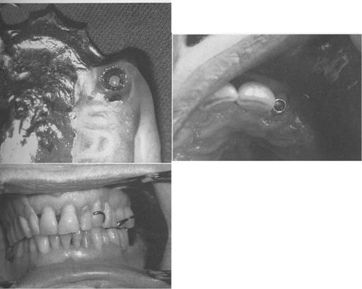
Fig. 7-62 Intracoronal magnets used for retention in partial denture applications. A, Magnets positioned on retained roots of canines. Keepers are cemented into endodontically treated roots, and' magnets are processed into the denture base. B, Cast and prosthesis illustrating the esthetic advantage and simplicity of using magnets for retention. (Courtesy Magnet-Dent Dental Ventures of America, Yorba Linda, Calif.) |
|
|
|
|
|
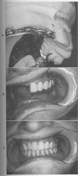
Fig. 7-63 Extracoronal spring-loaded plunger retaining device (Hannes Anchor/IC plunger). Permits full range of motion. A, Male plunger fits into dimple or female recess in porcelain-fused-to-metal crown located below height of contour on proximal surface of left central incisor. Band C, Acceptable retention and esthetics achieved if sufficient space is available. |
|
Chapter 7 |
|
Direct retainers |
|
|
|
A |
|
B |
|
c |
|
Fig. 7-64 Intracoronal retaining device (Servo Anchor-SA/Ceka). A, Female retaining device secured in denture base (spacing ring provides for variable resiliency). B, Threaded male stud and base soldered or cast to post and coping. C, Acceptable retention and esthetics achieved if sufficient space available to accommodate retaining device. |
|
|
|
|
|
|
|
McCracken's removable partial prosthodontics |
|
A |
|
B |
|
c |
|
Fig. 7-65 Intracoronal retaining device (Bona Ball). A, Female retaining device secured in denture base. B, Male stud cast or soldered to post and coping. C, Acceptable retention and esthetics if sufficient space available to accommodate retaining device. |
|
A |
|
B |
|
c |
|
Fig. 7-66 Intracoronal retaining device (Rotherman). A, Low-profile retaining device allows both hinge and vertical resiliency. Male stud cast or soldered to post and coping. B, Female retentive clip secured in denture base. Retention can be altered by compressing or spreading retention clips. C, Low profile provides acceptable esthetics. (Courtesy Dr. Jerry Walker, Milwaukee, Wis.) |
|
|
|
|
|
A |
|
B |
|
c |
|
Fig. 7-67 A, Cast with splinted crowns, Hader bar assembly, Hader bar clip, and two ERA receptors. B, Framework positioned on cast; ERA processing male components in place. C, Finished distal extension partial denture. |
|
Chapter 7 |
|
Direct retainers |
|
|
|
A |
|
B |
|
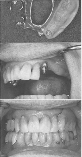
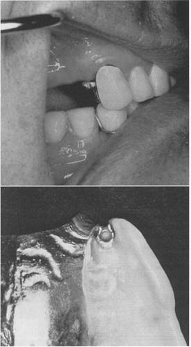
Fig. 7-68 A, Dalbo extracoronal attachment with L-shaped male portion attached to abutment crown on maxillary right canine; B, female sleeve placed in artificial tooth adjacent to abutment. |
|
|
|
|
|
A |
|
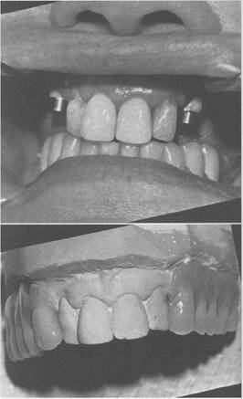
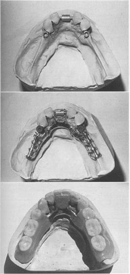
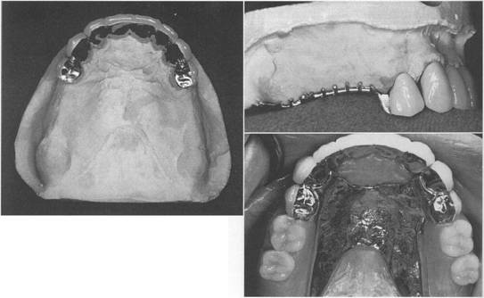
Fig. 7-69 A, Sterngold GL internal attachments with female portions cast into distal proximal surfaces of splinted maxillary first premolars. B, Profile view of male portion attached to partial denture frame. C, Finished partial denture with male portion seated into female portions within primary abutments. |
|
A |
|
c |
|
B |
|
c |
|
B |
|
D |
|
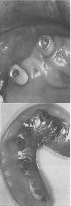
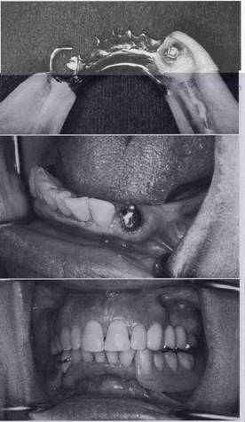
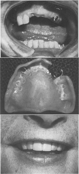
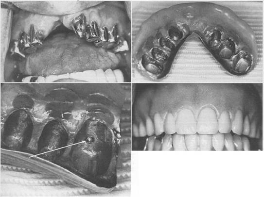
Fig. 7-70 Long copings on prepared natural abutments can provide support and retention in compromised dentition. A, Patient is adult with repaired Class IV cleft with resultant cross-bite, Class III occlusion, and severe anterior occlusal deficit. H, Internal surface of prosthesis fabricated to restore the arch. C, View of the internal overdenture structure with an IC attachment (arrow) that engages a dimpled crown preparation. Several such copings are placed to enhance retention. D, Labial view of completed overdenture prosthesis. |
|
Fig. 7-71 Low-profile coping contributes some additional retention but primarily provides improved support and stability. |
|
SELF-ASSESSMENT AIDS 1. The framework of a removable partial denture must furnish support, stabilization against horizontal (off vertical) movement, and mechanical retention. How is mechanical retention accomplished? 2. What factor other than mechanical retention contributes to resistance of the denture to dislodging forces? 3. What is the function of a direct retainer (clasp)? 4. There are basically two types of direct retainers. Draw and label their component parts in their correct positions on an abutment tooth. 5. Describe the principles by which the extracoronal direct retainer and the intracoronal retainer provide retention for the removable partial denture. 6. What is meant by the height of contour of an abutment tooth? 7. Draw a diagram of an abutment tooth and illustrate the angle of cervical convergence. |
|
Chapter 7 |
|
Direct retainers |
|
|
|
8. A direct retainer is an assembly of the following three components that perform individual function: (1) support, by a rest; (2) stabilization-reciprocation, by a rigid clasp arm or other rigid component; and (3) a retentive element. Do these elements necessarily have to arise from a common source? 9. Flexibility is permitted for which component of a clasp assembly? 10. The amount of retention that a direct retainer is capable of generating depends on three factors. What are these factors? 11. The retentive arm of a direct retainer must be flexible to engage an undercut with its terminal portion. Flexibility of the arm is a product of four physical and composition factors. What are these important factors? 12. Retention on all principal abutments should be as nearly equal as possible. To obtain this, which is the more important factor-the relation of the tip of the retentive arm to the height of contour or its depth in the angle of cervical convergence? 13. Describe the proportional tapers of a cast, half-round retentive arm. 14. Describe the taper of a cast, half-round stabilizing-reciprocal arm of a direct retainer assembly. For what reason must there be a difference in form between a retentive arm and a stabilizing-reciprocal arm? 15. Name the two basic types of retentive clasp arms. 16. A circumferential clasp arm approaches the retentive undercut from an occlusal direction. From which direction does a bar clasp arm approach the undercut? 17. A clasp assembly may be a combination of cast circumferential and bar clasp arms and! or wrought-wire retentive arms in one of several combinations. True or false? 18. A bar clasp arm is tapered in exactly the same way that a cast, half-round circumferential retentive clasp arm is tapered, differing only in configuration. Which arm is the more flexible if the two different arms are the same length? Why? |
|
|
|
McCracken's removable partial prosthodontics |
|
19. Permissible flexibilities of retentive cast circumferential and bar clasp arms based on length have been given in Tables 7-2 and 7-3. Can a O.7-inch bar-type arm be safely placed in the same depth of undercut that a 0.7-inch circumferential arm can? Based on the information contained in Tables 7-2 and 7-3, explain the differences between permissible flexibilities of duplicate retentive clasp arms made from a Type IV gold alloy and a chromium-cobalt alloy. 20. Cast clasp arms are essentially half-round in form, permitting flexing in only one direction. Which direction is this? 21. Wrought wire, I8-gauge round, is often used as a circumferential clasp arm. Its round form will permit flexing in which directions? 22. We speak of a reciprocal clasp arm. Explain what is meant by reciprocation and describe the condition that must be met for true reciprocation to occur. 23. A basic principle of direct retainer (clasp) design is that the retentive and reciprocal arms must encompass more than 180 degrees of the greatest circumference of the tooth, passing from diverging to converging axial surfaces. What would probably happen if a clasp failed to meet this criterion? 24. Simple mechanical laws (of levers) demonstrate that the closer a direct retainer assembly is located to the tipping axis of the tooth, the less likely that the periodontal ligament will be taxed from rotation tendencies of the denture. Draw the coronal portion of an abutment; divide the enamel crown into thirds; and locate support, retentive, stabilizing, and reciprocal components optimally. 25. Clasp retainers on abutment teeth adjacent to distal extension bases should be designed so that they will minimize direct transmission of tipping and rotational forces to the abutment. True or false? 26. The location of a usable undercut is perhaps the most important single factor in selecting a clasp for use with distal extension partial dentures. True or false? 27. There are many types and configurations of clasps; What factors are important to determine clasp retention and design? |
|
28. Under what circumstances may circumferential embrasure clasps be used? What are some real disadvantages of this type of retainer? 29. Give the indications for the use of a cast circumferential direct retainer. 30. What observations would lead to the selec tion of a bar-type clasp? 31. What is a combination clasp and what are the indications for its use? 32. State three advantages of the combination clasp. 33. Name the essential parts of a dental sur veyor. 34. There are six factors that determine the amount of retention a clasp is capable of generating. One of these is the type of metal from which it is made. Name the other five. 35. How does tilting the cast affect the selected areas available for clasp retention? 36. The provisions for support and retention are two of the six basic principles of design of an extracoronal retainer. What are the other four? 37. Draw four common errors in the design of a circumferential retainer. A bar-type retainer. 38. Would you agree that the single most important factor in selecting a type of direct retainer for a distal extension partial denture is the location of the undercut? Why? (Explain your answer.) 39. We know that guiding planes control the . . path of placement and removal of a remov able partial denture. Can they also contrib ute to additional retention? If :>0, how? 40. Explain why it i > neces:>ary for retentive clasp arms to be bilaterally opposed in Class I partial dentures. 41. In Class III partial dentures should the retention be bilaterally or diametrically op posed? Explain. 42. Differentiate between three basic approaches to the application of the RPI retainer system? 43. How does the amount of contact of the minor connector proximal plate with the corresponding guiding plane in the RPI system influence the way stress is transferred to the abutment tooth and the residual ridge? |
|