ALTE DOCUMENTE
|
|||||||
|
Direct retainers |
|
Internal Attachments Extracoronal Direct Retainers Relative uniformity <if retention Flexibility <1 clasp arms Stabilizing-reciprocal cast clasp arm Criteria for Selecting a Given Clasp Design |
|
A |
|
removable partial denture must have support that is derived from the abutment teeth through the use of rests and from the residual ridge through well-fitting bases. It must be stabilized against horizontal movement through the use of rigid connectors, indin_d retainers, and other stabilizing components. In addition, the removable partial denture must have sufficient retention to resist reasonable dislodging forces. Primary retention for the removable partial denture is accomplished mechanically by placing retaining elements on the abutment teeth. Secondary retention is provided by the intimate relationship of minor connector contact with the guiding planes, denture bases, and major connectors (maxillary) with the underlying tissues. The latter is similar to the retention of complete dentures and is proportionate to the accuracy of the impression registration, the accuracy of the fit of the denture bases, and the total area of contact involved. Mechanical retention of removable partial dentures is accomplished by means of direct retainers of one type or another. A direct |
|
|
|
Basic Principles of Clasp Design Circumferential clasp Bar clasp Combination clasp Other Types of Retainers Self-Assessment Aids |
|
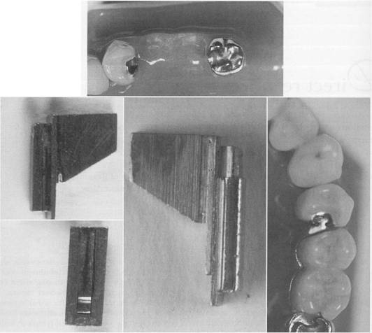
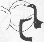
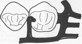
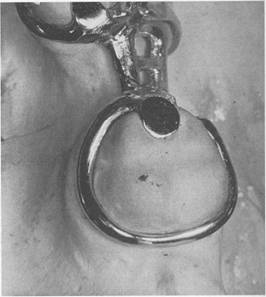
retainer is any unit of a removable dental prosthesis that engages an abutment tooth in such a manner as to resist displacement of the prosthesis away from basal seat tissues. This may be accomplished by frictional means, by engaging a depression in the abutment tooth, or by engaging a tooth undercut lying cervically to its height of contour. There are two basic types of direct retainers. One is the intra coronal retainer, which is cast or attached totally within the restored natural contours of an abutment tooth. This type of retainer is composed of a prefabricated machined key and keyway, with opposing vertical parallel walls that serve to limit movement and resist removal of the partial denture through frictional resistance (Fig. 7-1). The other type of retainer is the extracoronal retainer, which uses mechanical resistance to displacement by components placed on or attached to the external surfaces of an abutment tooth. There are three principal types of extracoronal retainers. One is the manufactured attachment, such as the Dalbo (Fig. 7-2). Others use a spring-loaded plunger that engages a contoured or restored depression |
|
|
|
|
|
|
|
McCracken's removable partial prosthodontics |
|
A |
|
B |
|
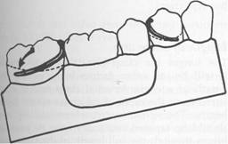
Fig. 7-1 lntracoronal retainer consists of a key and keyway with extremely small tolerance. A, Keyways are contained within abutment crowns, and B, keys are attached to removable partial denture framework. Frictional resistance to removal and placement and limitation of movement serve to retain and stabilize prosthesis. |
|
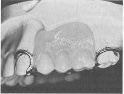
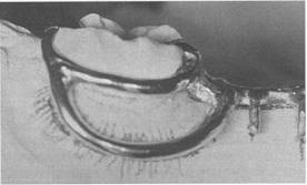
on the external surface of the abutment tooth and thereby resists displacement. A second type is a manufactured attachment that uses flexible clips or rings that engage a rigid component that is cast or attached to the external surface of an abutment crown. A third type is the clasp-type retainer (Figs. 7-3 and 7-4), in which a flexible arm engages an external surface of an abutment tooth in an area cervical to the greatest convexity of the tooth or engages a depression prepared to receive the terminal tip of the arm. The most |
|
common extra coronal attachment is the retentive clasp arm. The intracoronal retainer is usually regarded as an intemal attachment, or a precision attachment. The principle of the internal attachment was first formulated by Dr. Herman E.S. Chayes in 1906. One such attachment manufactured commercially still carries his name. Although it may be fabricated by the dental technician as a cast dovetail fitting into a counterpart receptacle in the abutment crown, the alloys used in |
|
|
|
|
|
|
|
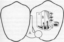
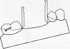
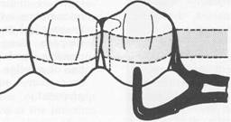
Fig.7-2 Dalbo extracoronal attachment. Components consist of A, L-shaped male portion that is attached to an abutment crown; B, female sleeve that is placed in artificial tooth adjacent to abutment, and coiled spring that fits into female portion. Design permits some vertical movement of denture under force through compression of coiled spring. |
|
manufactured attachments and the precision with which they are constructed make the ready-made attachment much. preferable to any of this type that can be fabricated in the dental laboratory. Much credit is due the manufacturers of metals used in dentistry for the continued improvements in the design of internal attachments. Numerous well-designed internal attachments are available in the dental marke\ that may be used in situations requiring special retention. Descriptive literature and technique manuals are available from the manufacturers. |
|
The internal attachment has two major advantages over the extracoronal attachment: elimination of visible retentive and support components, and better vertical support through a rest seat located more favorably in relation to the horizontal axis of the abutment tooth. For these reasons, the internal attachment may be preferable in selected situations. It provides horizontal stabilization similar to that of an internal rest; however, additional extracoronal stabilization is usually desirable. It has been claimed that stimulation to the underlying tissues is greater when internal attachments are |
|
B Lingual |
|
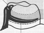
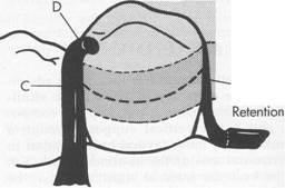
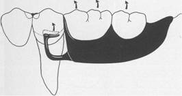
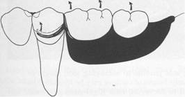
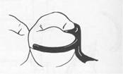
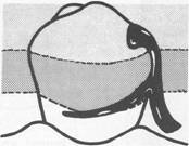
Fig. 7-3 Extracoronal circumferential direct retainer. Assembly consists of A, buccal retentive arm; B, rigid lingual stabilizing (reciprocal) arm; and C, supporting occlusal rest. Terminal portion of retentive arm is flexible and engages measured undercut. Assembly remains passive until activated by placement or removal of restoration or when subjected to masticatory forces that tend to dislodge the denture base. |
|
used because of intermittent vertical massage. This is probably no more than is possible with extracoronal retainers of similar construction. Some of the disadvantages of internal attachments are that (1) they require prepared abutments and castings; (2) they require somewhat complicated clinical and laboratory procedures; (3) they eventually wear, with progressive loss of frictional resistance to denture removal; (4) they are difficult to repair and replace; (5) they are effective in proportion to their length and are therefore least effective on short teeth; (6) they are difficult to place completely within the circumference of an abutment tooth because of the size of the pulp; and (7) they are considered more costly. |
|
A Buccal |
|
|
|
|
|
|
|
|
|
McCracken's removable partial prosthodontics |
|
Because the principle of the internal attachment does not permit horizontal movement, all horizontal, tipping, and rotational movements of the prosthesis are transmitted directly to the abutment tooth. The internal attachment therefore should not be used in conjunction with extensive tissue-supported distal extension denture bases unless some form of stress-breaker i:'i u:'ied between the movable base and the rigid attachment. Although stress-breakers may be used, they do have some disadvantages, which are discussed later, and their use adds to the cost of the partial denture. |
|
EXTRA CORONAL DIRECT RETAINERS |
|
Although the extracoronal, or clasp direct, retainer is used more often than the internal attachment, it is commonly misused. It is hoped that a better understanding of the principles of clasp design -will lead to a more intelligent use of this 15315r173p retainer. Critical areas of an abutment that provide for retention and stabilization (reciprocation) can only be identified with the use of a dental cast surveyor (Table 7-1). To enhance the under |
|
Component part |
|
Function |
|
Location |
|
Rest Minor connector |
|
Support Stabilization |
|
Clasp arms |
|
Stabilization (reciprocation) Retention |
|
Occlusal, lingual, incisal Proximal surfaces extending from a prepared marginal ridge to the junction of the middle and gingival one third of abutment crown Middle one third of crown Gingival one third of crown in measured undercut |
|
Support |
|
Stabilization |
|
B |
|
Buccal |
|
|
|
Support |
|
Stabilization |
|
B |
|
Lingual |
|
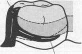
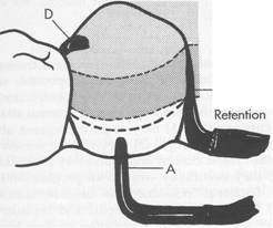
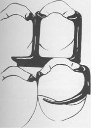
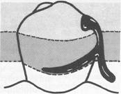
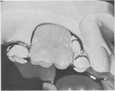
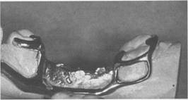
Fig. 7-4 Extracoronal bar-type direct retainer. Assembly consists of A, buccal retentive arm engaging measured undercut; B, stabilizing (reciprocal) elements; proximal plate minor connector on distal; C, lingually placed mesial minor connector for occlusal rest, which also serves as a stabilizing (reciprocal) component; and D, mesially placed supporting occlusal rest. Assembly remains passive until activated. |
|
|
|
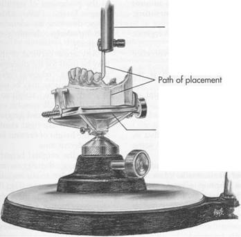
standing of direct retainers, an introduction of the dental cast surveyor is appropriate at this time. Surveying will be covered in detail in Chapter 11. The cast surveyor (Fig. 7-5) is a simple instrument essential to planning partial denture treatment. Its main working parts are the vertical arm and the adjustable table that holds the cast in a fixed relation to the vertical arm. This relationship of the vertical arm to the cast represents the path of placement that the partial denture will ultimately take when inserted or removed from the mouth. The adjustable table may be tilted in relation to the vertical arm of the surveyor, until a path that best satisfies all the factors involved can be found. A cast in a horizontal relationship to the vertical arm represents a vertical path of placement; a cast in a tilted relationship represents a path of placement toward |
|
Chapter 7 |
|
Direct retainers |
|
|
|
the side of the cast that is tilted upward. The vertical arm, when brought in contact with a tooth surface, will indicate the areas available for retention and those available for support, as well as the existence of tooth and other tissue interference to the path of placement. When the surveyor blade contacts a tooth on the cast at its greatest convexity, a triangle is formed. The apex of the triangle is at the point of contact of the surveyor blade with the tooth, and the base is the area of the cast representing the gingival tissues (see Fig. 11-19). The apical angle is called the angle of cervical convergence (Fig. 7-6). This angle may be measured as described in Chapter 11, or it may be estimated by observing the triangle of light visible between the tooth and the surveyor blade. For this reason a wide surveyor blade rather than a small cylindric tool |
|
Vertical spindle |
|
|
|
Adjustable table |
|
Fig.7-5 Essential parts of a dental surveyor (Ney Parallelometer), showing vertical spindle in relation to adjustable table. |
|
|
|
|
|
McCracken's removable partial prosthodontics |
|
A |
|
Path of placement I |
|
B |
|
Height of contour x |
|
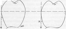
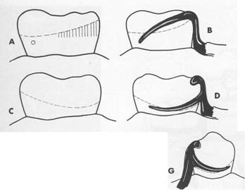
Fig. 7-6 Angle of cervical convergence on two teeth presenting dissimilar contours. Greater angle of cervical convergence on tooth A necessitates placement of clasp terminus, X, nearer the height of contour than when lesser angle exists, as in B. It is apparent that uniform clasp retention depends on depth (amount) of tooth undercut rather than on distance below the height of contour at which clasp terminus is placed. |
|
is used so that the triangle of light may be more easily seen. The following factors determine the amount of retention a clasp is capable of generating: |
|
1. Size of the angle of cervical convergence (depth of undercut) 2 How far into the angle of cervical convergence the clasp terminal is placed 3. Flexibility of the clasp arm, which is the product of: a. Its length, measured from its point of origin to its terminal end b. Its relative diameter, regardless of its cross-sectional form c. Its cross-sectional form or shape-that is, whether it is round, half-round, or some other form d. The material of which the clasp is madethat is, whether it is made of a cast gold alloy, cast chrome alloy, wrought gold alloy, wrought chrome alloy, titanium, or titanium alloy (each alloy has its own characteristics in both cast and wrought form) |
|
To be retentive a tooth must have an angle of col\vergence cervical to the height of contour. When it is surveyed, any single tooth will have a height of contour or an area of greatest convex |
|
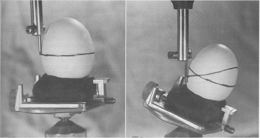
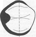
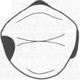
ity; areas of cervical convergence may not exist when the tooth is viewed in relation to a given path of placement. Also, certain areas of cervical convergence may not be usable for the placement of retentive clasps because of their proximity to gingival tissues. This is best illustrated by mounting a spherical object, such as an egg, on the adjustable table of a dental surveyor (Fig. 7-7, A). The egg now represents the cast of a dental arch or, more correctly, one tooth of a dental arch. The egg is first placed perpendicular to the base of the surveyor and surveyed to determine the height of contour. The vertical arm of the surveyor represents the path of placement that a denture would take and, conversely, its path of removal if it were placed and removed over this object. With a carbon marker a circumferential line is drawn on the egg at its greatest circumference. This line, which Kennedy called the height of contour, is its greatest convexity. Cummer spoke of it as the guideline because it is used as a guide in the placement of retentive and nonretentive clasps. To this, DeVan added the terms suprabulge, denoting the surfaces sloping superiorly, and infrabulge, denoting the surfaces sloping inferiorly. Any areas cervical to the height of contour may be used for the placement of retentive clasp components, whereas areas occlusal to the height of contour may be used for the placement of nonretentive, stabilizing, or reciprocating components. Obviously, only flexible components may be placed gingivally to the height of contour because rigid elements would not flex over the height of contour or contact the tooth in the undercut area. With the original height of contour marked on the egg, the egg is now tilted from the perpendicular to an angular relation with the base of the surveyor (Fig. 7-7, B). Its relation to the vertical arm of the surveyor has now been changed, just as a change in the position of a dental cast would bring about a different relationship with the surveyor. The vertical arm of the surveyor still represents the path of placement; however, its relation to the egg is totally different. Again, the carbon marker is used to delineate the height of contour or the greatest convexity. It |
|
|
|
Chapter 7 |
|
Direct retainers |
|
|
|
A |
|
B |
|
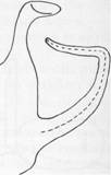
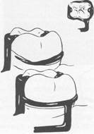
Fig. 7-7 A, When an egg is placed with its long axis parallel to surveying tool, height of contour is found at its greatest circumference. Similarly, height of contour may be identified on a single tooth when its long axis is placed parallel to surveying tool. Rigid parts of partial denture framework may be located in suprabulge areas above height of contour, whereas only flexible portions of clasp retainers may be placed in infrabulge areas below the height of contour. Those infrabulge surfaces that will be crossed by rigid parts of partial denture framework must be eliminated either during mouth preparations or by blockout. B, If same egg is tilted in relation to vertical spindle of surveyor, areas formerly infrabulge are now found to be suprabulge and will accommodate only nonretentive denture components. At the same time, however, areas formerly suprabulge or only slightly infrabulge are found to be so severely undercut that design and location of clasp retainers must be changed. Unfortunately, no single tooth in a partially edentulous arch may govern relation of cast to surveyor and thus the path of placement of partial denture. A compromise position must be found that, following mouth preparations, will satisfy all four factors: (1) no interference to placement; (2) effective location of retentive components; (3) most esthetic placement of all component parts; and (4) existence of guiding planes that will ensure stabilization of the partial denture and a definite path of placement and removal. |
|
will be seen that areas that were formerly infrabulge are now suprabulge, and vice versa. A retentive clasp arm placed below the height of contour in the original position may now be either excessively retentive or totally nonretentive, whereas a nonretentive stabilizing or reciprocal arm that is located above the height of contour in the first position now may be located in an area of undercut. The location and depth of a tooth undercut available for retention are therefore only relative to the path of placement and removal |
|
of the partial denture; at the same time, nonretentive areas on which rigid components of the clasp may be placed exist only for a given path of placement (Fig. 7-8). If conditions are found that are not favorable for the particular path of placement being considered, the conditions produced by a differ ent path of placement should be studied. The cast is merely tilted in relation to the vertical arm until the most suitable path is found. The most suitable path of placement is generally considered to be the path of placement that |
|
|
|
|
|
|
|
McCracken's removable partial prosthodontics |
|
lifting force |
|
lifting force |
|
Fig. 7-8 Retention is provided primarily by flexible portion of clasp assembly. Retentive terminals are ideally located in measured undercuts in gingival third of abutment crowns. When force acts to dislodge restoration in occlusal direction, retentive arm is forced to deform as it passes from undercut location over height of contour. Amount of retention provided by clasp arm is determined by its length, diameter, taper, cross-sectional form, contour, type of alloy, and location and depth of undercut engaged. |
|
will require the least amount of mouth preparation necessary to place the components of the partial denture in their ideal position on the tooth surfaces and in relation to the soft tissues. Then mouth preparations are planned with a definite path of placement in mind. It is of primary importance to remember that tooth surfaces can be recontoured by selective grinding or the placement of restorations (mouth preparations) to achieve a more suitable path of placement or removal. The path of placement also must take into consideration the presence of tissue undercuts that will interfere with the placement of major connectors, the |
|
location of vertical minor connectors, the origin of bar clasp arms, and the denture bases. When the theory of clasp retention is applied to the abutment teeth in a dental arch during the surveying of the dental cast, each tooth may be considered individually and in relation to the other abutment teeth as far as the designs of retentive and stabilizing (reciprocating) components are concerned. This is necessary because the relationship of each tooth to the rest of the arch and to the design of the rest of the prosthesis has been considered previously in selecting or modifying the teeth to achieve the most suitable path of placement. Once this relationship of the cast to the surveyor has been established, the height of contour on each abutment tooth becomes fixed, and the clasp design for each must be considered separately. Clasp retention is based on the resistance of metal to deformation. For a clasp to be retentive, it must be placed in an undercut area of the tooth, where it is forced to deform when a vertical dislodging force is applied. It is this resistance to deformation that generates retention (Fig. 7-9). Such resistance is proportionate to the flexibility of the clasp arm. A positive path of placement and removal is made possible by the contact of rigid parts of the denture framework with parallel tooth surfaces, which act as guiding planes. Because guiding planes control the path of placement and removal, they can also provide additional retention for the partial denture by limiting the possibilities that exist for its dislodgement. The more vertical walls (guiding planes) that are prepared parallelvthe fewer the possibilities that exist for dislodgement. If some degree of parallelism does not exist during placement and removal, trauma to the teeth and supporting structures, as well as strain on the denture parts, is inevitable. This ultimately results in damage either to the teeth and their periodontal support or to the denture itself or both. Therefore without guiding planes, clasp retention will either be detrimental or practically nonexistent. If clasp retention is only frictional because of an active relationship of the clasp to the teeth, then orthodontic movement, damage to periodontal tissues, or both will result. Instead, a clasp should bear a passive relationship to the |
|
|
|
|
|
|
|
|
|
|
|
I |
|
A |
|
Chapter 7 |
|
Direct retainers |
|
|
|
c |
|
B |
|
D |
|
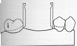
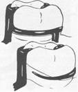
j Fig.7-9 A, Retentive areas are not sufficient to resist reasonable dislodging forces when cast is surveyed at its most advantageous position (occlusal plane parallel to surveyor table) even though guide planes could be established with minor tooth modification. B, Tilting cast creates functionally ineffective tooth contours, which are present only in relation to surveying rod and do not exist when compared with most advantageous position (position in which restoration will be subject to dislodging forces in an occlusal direction). C and D, Clasps designed at tilt are ineffective without development of corresponding guide planes to resist displacement when restoration is subject to dislodging forces in occlusal direction. |
|
the time being, variations in clasp flexibility, relative uniformity of retention will depend on the location of the retentive part of the clasp arm, not in relation to the height of contour, but in relation to the angle of cervical convergence. The retention on all principal abutments should be as nearly equal as possible. |
|
teeth except when a dislodging force is applied. |
|
Relative uniformity of retention The size of the angle of convergence will determine how far into that ;;mgle a given clasp arm should be placed. Disregarding, for |
|
|
|
|
|
|
|
McCracken's removable partial prosthodontics |
|
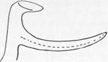
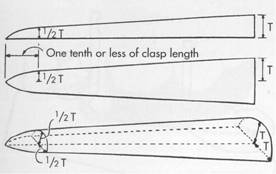
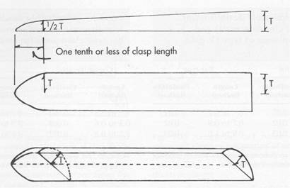
Fig.7-10 Retentive cast clasp arm should be tapered uniformly from its point of attachment at clasp body to its tip. Dimensions at tip are about half those at point of attachment. Clasp arm so tapered is approximately twice as flexible as one without any taper. Tis clasp thickness. (Courtesy J.E Jelenko & Company, New York, NY.) |
|
|
|
Fig. 7-11 length of cast retentive clasp arm is measured along center portion of arm until it either joins clasp body (circumferential) or until it becomes part of denture base or is embedded in the base (bar-type clasp). |
|
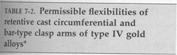
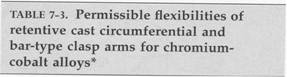
Length of clasp arm The longer the clasp arm, the more flexible it will be, all other factors being equal. The length of a circumferential clasp arm is measured from the point at which a uniform taper begins. The retentive circumferential clasp arm should be tapered uniformly from its point of origin through the full length of the clasp arm (Fig. 7-10). The length of a bar clasp arm also is measured from the point at which a uniform taper begins. Generally the taper of a bar clasp " arm should begin at its point of origin from a metal base or at the point at which it emerges from a resin base (Fig. 7-11). Although a bar clasp arm will usually be longer than a circum ferential clasp arm, its flexibility will be less because its half-round form lies in several planes, which prevents its flexibility from being proportionate to its total length. Tables 7-2 and 7-3 give an approximate depth of undercut that may be used for the cast gold and chromium cobalt retentive clasp arms of circumferential and bar-type clasps. Based on a proportional limit of 60,000 psi and on the assumption that the clasp arm is properly tapered, the clasp arm should be able to flex repeatedly within the limits stated without hardening or ruptur ing because of fatigue. It has been estimated that alternate stress applications of the fatigue type are placed on a retainer arm during |
|
Although esthetic placement of clasp arms is desirable, it may not be poSsible to place all clasp arms in the same occlusocervical relationship because of variations in tooth contours. However, retentive surfaces may be made similar by altering tooth contours or by placing cast restorations with similar contours. Retentive clasp arms must be located so that they lie in the same approximate degree of undercut on each abutment tooth. In Fig. 7-6 this is at point X on both teeth, A and B, despite the variation in the distance below the height of contour. Should both clasp arms be placed equidistant below the height of contour, the higher location on tooth B would have too little retention, whereas the lower location on tooth A would be too retentive. The measurement of the degree of undercut by mechanical means is therefore most important. Although experience with undercut gauges is important, the student should have a thorough comprehension of all the factors influencing clasp retention and be able to apply them intelligently Flexibility of clasp arms The following factors influence the flexibility of a clasp arm. |
|
|
|
|
|
Circumferential |
|
Bar-type |
||
|
Length |
Flexibility |
|
Length |
Flexibility |
|
(inches) |
(inches) |
|
(inches) |
(inches) |
|
0 to 0.3 |
|
|
to 0.7 |
|
|
0.3 to 0.6 |
|
0.7 to 0.9 |
|
|
|
0.6 to 0.8 |
|
0.9 to 1.0 |
|
|
|
'Based on the approximate dimensions of Jelenko preformed plastic patterns, JF Jelenko, New York, NY. |
|
mastication and other force-inducing functions about 300,000 times a year. Diameter of clasp arm The greater the average diamete-r of a clasp arm, the less flexible it will be, all other factors being equal. If its taper is absolutely uniform, the average diameter will be at a point midway between its origin and its terminal end. If its taper is not uniform, a point of flexure, and therefore a point of weakness, will exist that will then be the determining factor in its flexibility, regardless of the average diameter of its entire length. |
|
Cross-sectional form of the clasp arm Flexibility may exist in any form, but it is limited to only one direction in the case of the half-round form. The only universally flexible form is the round form, which is practically impossible to obtain by casting and polishing. Because most cast clasps are essentially half round in form, they may flex away from the tooth, but edgewise flexing (and edgewise adjustment) is limited. For this Jeason, cast retentive clasp arms are more acceptable in tooth supported partial dentures in which they are called on to flex only during placement and removal of the prosthesis. A retentive clasp arm on an abutment adjacent to a distal extension base not only must flex during placement and removal but also must be capable of flexing during functional movement of the distal extension base. It must |
|
Chapter 7 |
|
Direct retainers |
|
|
|
|
Circumferential |
|
Bar-type |
||
|
|
Length |
Flexibility |
|
Length |
Flexibility |
|
|
(inches) |
(inches) |
|
(inches) |
(inches) |
|
|
to 0.3 |
|
|
to 0.7 |
|
|
0.3 to 0.6 |
|
0.7 to 0.9 |
|
||
|
0.6 to 0.8 |
|
0.9 to 1.0 |
|
||
|
*Based on the approximate dimensions of Jelenko preformed plastic patterns, JF Jelenko, New York, NY. |
|
either have universal flexibility to avoid transmission of tipping stresses to the abutment tooth or be capable of disengaging the undercut when vertical forces directed against the denture are toward the residual ridge. A round clasp form is the only circumferential clasp form that may be safely used to engage a tooth undercut on the side of an abutment tooth away from the distal extension base. The location of the undercut is pex;haps the single most important factor in selecting a clasp for use with distal extension partial dentures. |
|
Material used for the clasp arm Although all cast alloys used in partial denture construction possess flexibility, their flexibility is proportionate to their bulk. If this were not true, other components of the partial denture could not have the necessary rigidity. A disadvantage of a cast gold partial denture is that its bulk must be increased to obtain the needed rigidity at the expense of added weight and increased cost. It cannot be denied that greater rigidity with less bulk is possible through the use of chromium-cobalt alloys. Although cast gold alloys may have greater resiliency than do cast chromium-cobalt alloys, the fact remains that the structural nature of the cast clasp does not approach the flexibility and adjustability of the wrought-wire clasp. Having been formed by being drawn into a wire, the wrought-wire clasp arm has toughness exceeding that of a cast clasp arm. The tensile strength of |
|
|
|
McCracken's removable partial prosthodontics |
|
Fig. 7-12 Reciprocal arm of direct retainer assembly should be rigid. Arm tapered both lengthwise and widthwise is more flexible than arm of the same dimensions tapered only lengthwise. T is clasp thickness. |
|
a wrought structure is at least 25% greater than that of the cast alloy from which it was made. It may therefore be used in smaller diamete'rs to provide greater flexibility without fatigue and ultimate fracture. |
|
Stabilizing-reciprocal cast clasp arm A stabilizing (reciprocal) clasp arm should be rigid. Therefore it is shaped somewhat differently than is the cast retentive clasp arm, which must be flexible. Its average diameter must be greater than the average diameter of the opposing retentive arm to increase desired rigidity. A cast retentive arm is tapered in two dimensions, as illustrated in Fig. 7-10, whereas a reciprocal arm should be tapered in one dimension only, as shown in Fig. 7-12. To achieve such a form for the arm, freehand waxing of patterns is required. |
|
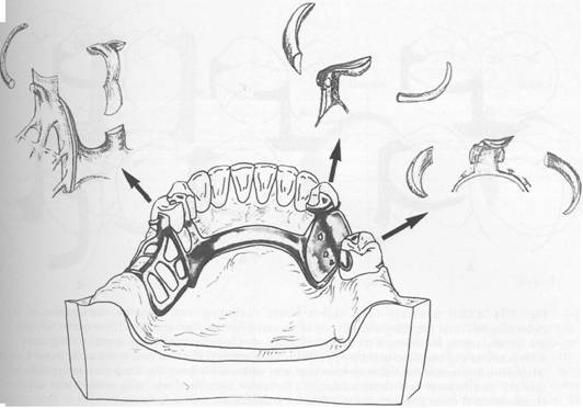
should not expect the technician to make the decision as to which clasp design is to be used. The choice of clasp design must be both biologically and mechanically sound, based on the diagnosis and treatment plan previously established. Extracoronal direct retainers should be considered as a combination of components of a removable partial denture framework, designed and located to perform the specific functions of support, stabilization, reciprocation, and retention. It matters not whether the direct retainer assembly components are physically attached directly to each other or originate from major and minor connectors of the framework (Fig. 7-13). If attention is directed to the separate function of each component of the direct retainer assembly, then designing a direct retainer for a particular situation is simplified. The advantages of any particular clasp design should lie in an affirmative answer to most (or all) of the following questions: 1. Is it flexible enough to satisfy the purpose for which it is being used? (On an abutment adjacent to a distal extension base, will tipping and torque be avoided?) 2. Will adequate stabilization be provided to resist horizontal and rotational movements? |
|
CRITERIA FOR SELECTING A GIVEN CLASP DESIGN In selecting a particular clasp design for a given situation, its function and limitations must be carefully evaluated. The dentist |
|
|
|
|
|
Chapter 7 |
|
Direct retainers |
|
|
|
Fig.7-13 Choice and definitive location of each component of direct retainer assembly must be based on preserving health of periodontal attachment in spite of rotational tendencies of distal extension denture. Knowledge of characteristics of each component of collective assemblies for a particular arch and rationalized rotational tendencies of denture simplifies design of removable restorations. |
|
3. Will rigidity be provided where it is needed? 4. Is the clasp design applicable to malposed or rotated abutment teeth? 5. Can it be used despite the presence of tissue undercuts? 6. Can the clasp terminal be adjusted to increase or decrease retention? 7. Does the clasp arm cover a minimum of tooth surface? 8. Will the clasp arm be as inconspicuous as possible? 9. Will the width of the occlusal table remain the same or be decreased? 10. Is the clasp arm likely to become distorted or broken? If so, can it be replaced? |
|
With this background the various types of clasps will be considered. The choice of a clasp is like the choice of a tool to be used in a given situation. Knowing what types are available and being familiar with their various advantages and limitations permit selection of a clasp design that best meets the needs of the individual situation. Although there are some rather complex designs for clasp arms, they may all be classified into one of two basic categories. One is the circumferential clasp arm, which approaches the retentive undercut from an occlusal direction. The other is the bar clasp arm, which approaches the retentive undercut from a cervical direction. |
|
" |
|
|
|
|
|
|
|
|
|
|
|
McCracken's removable partial prosthodontics |
|
A |
|
B |
|
c |
|
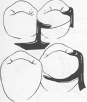
Fig. 7-14 Clasp assembly (with mirror views), including rest, may be combination of circumferential and bar clasp arms in one of several possible combinations. These mirror views are for abutments bounding a modification space. A, Cast circumferential retentive clasp arm with nonretentive bar clasp arm on opposite side for stabilization and reciprocation. B, Tapered wrought-wire circumferential retentive clasp arm with nonretentive bar clasp arm on opposite side for stabilization and reciprocation. C, Retentive bar clasp arm with nonretentive cast circumferential clasp arm on opposite Side for stabilization and reciprocation. |
|
A clasp assembly may be a combination of cast circumferential and bar clasp arms and/or wrought-wire retentive arms in one of several possible combinations, as illustrated in buccal and lingual views in Fig. 7-14. No confusion should exist between the choice of clasp arm and the purpose for which it is used. Either type of cast clasp arm may be made tapered and retentive or nontapered (rigid) and nonretentive, depending on whether it is used for retention, stabilization, or reciprocation. A clasp assembly should consist of (1) one or more minor connectors from which the clasp compo::: nents originate; (2) a principal rest; (3) a retentive arm engaging a tooth undercut only at its terminus; and (4) a nonretentive arm or other component on the opposite side of the tooth for stabilization and reciprocation against horizontal movement of the prosthesis. Rigidity of this clasp arm is essential to its purpose. An auxiliary occlusal rest may be used rather than a reciprocal clasp arm if it is located in a way to |
|
|
|
accomplish the same purpose (Fig. 7-15). The addition of a lingual apron to a cast reciprocal clasp arm alters neither its primary purpose nor the need for proper location to accomplish that purpose. |
|
BASIC PRINCIPLES OF CLASP DESIGN |
|
Any clasp assembly must satisfy the basic principle of clasp design, which is that more than 180 degrees of the greatest circumference of the crown of the tooth must be included, passing from diverging axial surfaces to converging axial surfaces (Fig. 7-16). This may be in the form of continuous contact when circumferential clasp arms are used. When bar clasp arms are used, at least three widely separated areas of tooth contact must embrace more than one half of tooth circumference. These are the occlusal rest area, the retentive terminal area, |
|
|
|
|
|
|
|
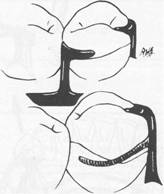
Fig.7-15 Auxiliary occlusal rest (mirror view) may be used rather than reciprocal clasp arm without violating any principle of clasp design. Its greatest disadvantages are that second rest seat must be prepared and that enclosed tissue space at the gingival margin can result in a food trap. Auxiliary occlusal rest is also sometimes used to prevent slippage when principal occlusal rest seat cannot be inclined apically from marginal ridge. Minor connectors used to close interproximal space most often require rests on adjacent teeth to avoid wedging effect when force is placed on denture. |
|
and the reciprocal terminal area. Other principles to be considered in the design of a clasp are as follows: 1. The occlusal rest must be designed so that movement of the clasp arms cervlcally is prevented. 2. Each retentive terminal should be opposed by a reciprocal component capable of resisting any orthodontic pressures exerted by the retentive arm. Stabilizing and reciprocal components must be rigidly connected bilaterally (cross-arch) if reciprocation to the retentive elements is to be realized (Fig. 7-17). 3. Unless guiding planes will positively control the path of removal and stabilize abutments against rotational movements, retentive clasps should be bilaterally opposed; that is, buccal retention on one side of the arch |
|
Chapter 7 |
|
A |
|
Buccal I I |
|
Lingual |
|
Direct retainers |
|
|
|
Buccal |
|
B |
|
Lingual |
|
Fig. 7-16 A, Line drawn through illustration represents 180 degrees of greatest circumference of abutment from occlusal rest. Unless portions of lingual reciprocal arm and retentive buccal arm are extended beyond the line, clasp would not accomplish its intended purpose. If respective arms of retainer were not extended beyond the line, abutment tooth could be forced away from retainer by torquing action of clasp or removable partial denture could move away from abutment. B, Bar-type clasp assembly engagement of more than 180 degrees of circumference of abutment is realized by minor connector for occlusal rest, minor connector contacting guiding plane on distal proximal surface, and retentive bar arm. |
|
should be opposed by buccal retention on the other, or lingual on one side opposed by lingual on the other. In Class II situations the third abutment may have either buccal or lingual retention. In Class III situations, retention may be either bilaterally or diametrically opposed (Fig. 7-18). 4. The path of escapement of each retentive clasp terminal must be other than parallel to the path of removal of the prosthesis (see Fig. 7-8). 5. The amount of retention should always be the minimum necessary to resist reasonable dislodging forces. |
|
|
|
|
|
McCracken's removable partial prosthodontics |
|
AUV |
|
.LVV <-- _ +-- ? |
|
Fig. 7-17 A, Flexing action of retentive clasp arm initiates medially directed pressure on abutment teeth as its retentive tip springs over height of contour. B, Reciprocation to medially directed pressure is counteracted either by rigid lingually placed clasp arms contacting abutments simultaneously with buccal arms or by rigid stabilizing components of ') framework contacting lingual guiding planes when buccal arms begin to flex. |
|
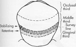
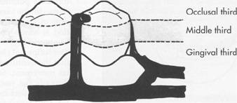
6. Clasp retainers on abutment teeth adjacent to distal extension bases should be designed so that they will avoid direct transmission of tipping and rotational forces to the abutment. In effect, they must act as stressbreakers either by their design or by their construction. This is accomplished by proper location of the retentive terminal or by use of a more flexible clasp arm in relation to prospective rotation of the denture under varying directed forces. 7. Ideally, reciprocal elements of the clasp _ assembly should be located at the junction of the gingival and middle thirds of the crowns of abutment teeth. The terminal end of the retentive arm is optimally placed in the gingival third of the crown (Figs. 7-19 through 7-21). These locations will permit the abutment teeth to better resist horizontal and torquing forces than they could if the retentive and reciprocal elements were located nearer the occlusal or incisal surfaces. As a metaphor, remember that a fencepost is more easily loosened by applying horizontal forces |
|
A |
|
B |
|
c |
|
Fig. 7-18 A, Retentive clasps should be bilaterally opposed. B, In Class II situations the retention on the third abutment may be on the buccal or the lingual. C, In Class III situations, retention may be either (a) bilateral or (b) diametrically opposed. |
|
|
|
Fig. 7-19 Simple mechanical laws demonstrate that the nearer stabilizing-reciprocal and retentive elements of direct retainer assemblies are located to horizontal axis of rotation of abutment, the less likely that physiologic tolerance of periodontal ligament will be exceeded. Horizontal axis of rotation of abutment tooth is located somewhere in its root. |
|
near the top than by applying the same forces nearer ground level. The reciprocal clasp arm has the following three functions: 1. The reciprocal clasp arm should provide stabilization and reciprocation against the action of the retentive arm. This is particularly important if the retentive arm is accidentally distorted toward the tooth, where it would become an active orthodontic force. Remember, the retentive clasp arm should be passive until a dislodging force is applied. During placement and removal, reciprocation is needed as the retentive arm flexes over the height of contour. Unless the abutment tooth has been specifically contoured, the reciprocal clasp arm will not come into contact with the tooth until the denture is fully seated and the retentive clasp arm has again become passive. When this happens, a momentary tipping force is applied to the abutment teeth during each placement and removal. This may not be a damaging force, because it is transient, so long as the force does not exceed the normal elasticity of the periodontal attachments. True reciprocation during placement |
|
Chapter 7 |
|
Direct retainers |
|
|
|
and removal is possible only through the use of crown surfaces made parallel to the path of placement. The use of cast restorations permits the paralleling of the surfaces to be contacted by the reciprocal arm in such a manner that true reciprocation is made possible. This is discussed in Chapter 14. 2. The reciprocal clasp arm should be located so that the denture is stabilized against horizontal movement. Stabilization is possible only through the use of rigid clasp arms, rigid minor connectors, and a rigid major connector. Horizontal forces applied on one side of the dental arch are resisted by the stabilizing components on the opposite side providing cross-arch stability. Obviously the greater the number of such components, within reason, the greater will be the distribution of horizontal stresses. 3. The reciprocal clasp arm may act to a minor degree as an indirect retainer (see Fig. 8-1). This is only true when it rests on a suprabulge surface of an abutment tooth lying anterior to the fulcrum line (see Fig. 8-8). Lifting of a distal extension base away from the tissues is thus resisted by a rigid arm, which is not easily displaced cervically. The effectiveness of such an indirect retainer is limited by its proximity to the fulcrum line, which gives it a relatively poor leverage advantage, and by the fact that slippage along tooth inclines is always possible. The latter may be prevented by the use of a ledge on a cast restoration; however, enamel surfaces are not ordinarily so prepared. |
|
Circumferential clasp Although a thorough knowledge of the principles of clasp design should lead to a logical application of those principles, it is better that some of the more common clasp designs be considered individually. The circumferential clasp will be considered first as an all-cast clasp. The circumferential clasp is usually the most logical clasp to use with all tooth-supported |
|
|
|
|
|
|
|
|
|
McCracken's removable partial prosthodontics |
|
A |
|
Retention |
|
Support Stabilization |
|
lingual |
|
Occlusal |
|
Retention |
|
Occlusal third |
|
Support Stabilization |
|
Middle third |
|
c |
|
Gingival third |
|
Buccal |
|
Fig. 7-20 Bar-type clasp on mandibular premolar. A, Support is provided by occlusal rest. B, Stabilization is provided by occlusal rest and mesial and distal minor connectors. C, Retention is provided by buccal I-bar. Reciprocation is obtained through location of minor connectors. Engagement of more than 180 degrees of circumference of the abutment is accomplished by proper location of components contacting axial surfaces. (Minor connector supports occlusal rest, proximal plate minor connector, and buccal I-bar.) |
|
|
|
|
|
|
|
Support |
|
Stabilization |
|
Retention |
|
Support |
|
Stabilization |
|
Retention |
|
Chapter 7 |
|
Direct retainers |
|
|
|
Occlusal third |
|
Middle third |
|
Gingival third |
|
Buccal |
|
Occlusal third |
|
Middle third |
|
Gingival third |
|
Lingual |
|
Fig.7-21 Circumferential clasp on mandibular premolar (mirror view). Support is provided by occlusal rest; stabilization is provided by occlusal rest, proximal minor connector, lingual clasp arm, and rigid portion of buccal retentive clasp arm occlusal to height of contour; retention is realized by retentive terminal of buccal clasp arm; reciprocation is provided by nonflexible lingual clasp arm. Assembly engages more than 180 degrees of abutment tooth's circumference. |
|
partial dentures because of its retentive and stabilizing ability (Fig. 7-22). Only when the retentive undercut may be approached better with a bar clasp arm or when esthetics will be enhanced should the latter be used (Fig. 7-23). The circumferential clasp arm does have the following disadvantages: 1. More tooth surface is covered than with a bar clasp arm because of its occlusal origin. 2. On some tooth surfaces, particularly the buccal surface of mandibular teeth and the lingual surfaces of maxillary teeth, its occlusal approach may increase the width of the occlusal surface of the tooth. 3. In the mandibular arch, more metal may be displayed than with the bar clasp arm. 4. As with all cast clasps, its half-round form prevents adjustment to increase or decrease |
|
Fig. Cast circumferential retentive clasp arms properly designed. They originate on or occlusal to height of contour, which they then cross in their terminal third, and engage retentive undercuts progressively as their taper decreases and their flexibility increases. |
|
|
|
|
|
|
|
McCracken's removable partial prosthodontics |
|
Fig. 7-23 Example of the two types of cast clasps in use. Molar abutment is engaged by circumferential clasp originating occlusal to height of contour, whereas premolar abutment is engaged by bar clasp originating from base gingival to height of contour. However, only terminal tip of this clasp is placed in measured undercut. |
|
" |
|
retention. Adjustments in the retention afforded by a cast clasp arm should be made by moving a clasp terminal cervically into the angle of cervical convergence or occlusally into a lesser area of undercut Tightening a clasp against the tooth or loosening it away from the tooth increases or decreases frictional resistance and does not affect the retentive potential of the clasp. True adjustment is, therefore, impossible with most cast clasps. Despite its disadvantages the cast circumfer ential clasp arm may be used effectively, and many of these disadvantages may be minimized by mouth preparation. Adequate mouth preparation will permit its point of origin to be placed far enough below the occlusal surface to avoid poor estheticsJand increased tooth dimension (see Fig. 7-22). Although some of the disadvantages listed imply that the bar-type clasp may be preferable, the circumferential clasp is actually superior to a bar clasp arm that is improperly used or poorly designed. Experience has shown that the possible advantages of the bar clasp arm are too often negated by faulty application and design, whereas the circumferential clasp arm is not as easily misused. The basic form of the circumferential clasp is |
|
Fig. 7-24 Cast circumferential retentive clasp arm. |
|
a buccal and lingual arm originating from a common body (Fig. 7-24). This clasp is used improperly when two retentive clasp arms originate from the body and occlusal rest areas and approach bilateral retentive areas on the side of the tooth away from the point of origin. The correct form of this clasp has only one retentive clasp arm, opposed by a nonretentive reciprocal arm on the opposite side. A common error is to use this clasp improperly by making both clasp terminals retentive. This not only is unnecessary but also disregards the need for reciprocation and bilateral stabilization. Other common errors in the design of circumferential clasps are illustrated in Fig. 7-25. |
|
Ring clasp The circumferential type of clasp may be used in several forms. It appears as though many of these forms of the basic circumferential clasp design were developed to accommodate situations in which corrected tooth modifications could not be or were not accomplished by the dentist. One is the ring clasp, which encircles nearly all of a tooth from its point of origin (Fig. 7-26). It is used when a proximal undercut cannot be approached by other means. For example, when a mesiolingual undercut on a lower molar abutment cannot be approached directly because of its proximity to the occlusal rest area and cannot be approached with a bar clasp arm because of lingual inclination of the tooth, the ring clasp encircling the tooth allows the undercut to be approached from the distal aspect of the tooth. The clasp should never be used as an unsupported ring (Fig. 7-27) because if it is free to open and close as a ring, it cannot provide either reciprocation or stabilization. Instead the ring-type clasp should always be used with a supporting strut on the non retentive side, with or |
|
|
|
|
|
|
|
Direct retainers |
|
|
|
Chapter 7 |
|
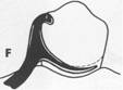
Fig. 7-25 Some improper applications of circumferential clasp design and their recommended corrections. A, Tooth with undesirable height of contour in its occlusal third. B, Unsuitable contour and location of retentive clasp arm on unmodified abutment. C, More favorable height of contour achieved by modification of abutment. D, Retentive clasp arm properly designed and located on modified abutment. E, Unsuitable contour and location of retentive arm in relation to height of contour (straight arm configuration provides poor approach to retentive area and is less resistant to dislodging force). F, Terminal portion of retentive clasp arm located too close to gingival margin. G, Clasp arm that is properly designed and located. |
|
without an auxiliary occlusal rest on the opposite marginal ridge. The advantage of an auxiliary rest is that further movement of a mesially inclined tooth is prevented by the presence of a distal rest. In any event the supporting strut should be regarded as being a minor connector from which the flexible retentive arm originates. Reciprocation then comes from the rigid portion of the clasp lying between the supporting strut and the principal occlusal rest (Figs. 7-28 and 7-29). The ring-type clasp should be used on protected abutments whenever possible because it covers such a large area of tooth surface. Esthetics need not be considered on such a posteriorly located tooth. A ring-type clasp may be used in reverse on an abutment located anterior to a tooth-bounded edentulous space (Fig. 7-30). Although potentially an effective clasp, this clasp covers an excessive amount of tooth surface and can be |
|
esthetically objectionable. The only justification for its use is when a distobuccal or distolingual undercut cannot be approached directly from the occlusal rest area and/or tissue undercuts prevent its approach from a gingival direction with a bar clasp arm. Back-action clasp The back-action clasp is a modification of the ring clasp, with all of the same disadvantages and no apparent advantages (Fig. 7-31). It is difficult to justify its use. The undercut can usually be approached just as well using a conventional circumferential clasp, with less tooth coverage and less display of metal. With the circumferential clasp the proximal tooth surface can be used as a guiding plane, as it should be, and the occlusal rest can have the rigid support it requires. An occlusal rest always should be attached to some rigid minor |
|
|
|
|
|
|
|
|
|
|
|
|
|
McCracken's removable partial prosthodontics |
|
B |
|
A |
|
|
|
Fig. 7-26 Ring clasp(s) en!=ircling nearly all of tooth from its point of origin. A, Clasp originates on mesiobuccal surface and encircles tooth to engage mesiolingual undercut. B, Clasp originates on mesiolingual surface and encircles tooth to engage mesiobuccal undercut. In either example, supporting strut is used on nonretentive side (drawn both as direct view of near side of tooth and as mirror view of opposite side). |
|
Fig. 7-28 Buccal strut supporting mesially originating ring clasp. Flexible retentive arm begins at distal occlusal rest and engages mesiolingual undercut. Despite its resemblance to bar-type clasp, this is a circumferential clasp by reason of its point of origin, the strut being actually an auxiliary minor connector. |
|
Fig. 7-27 Improperly designed ring clasp lacking necessary support. Such a clasp lacks any reciprocating or stabilizing action because entire circumference of clasp is free to open and close. Supporting strut should always be added on nonretentive side of abutment tooth, which then becomes, in effect, a minor connector from which tapered and flexible retentive clasp arm originates. |
|
Fig. 7-29 Ring clasp engaging mesiobuccal undercut on mesially inclined lower right molar requires supporting bar on lingual surface to limit flexure to only retentive portion of clasp. |
|