Construction Outline:
Build wing, ailerons, fin & rudder, stabilizer & elevators
Install hinges.
Build central portion of fuselage with fuselage sides FS1 and formers F2 - F12.
Install wing mounts and bolt wing to fuselage
Install stabilizers without elevators
Add F13
Sheet bottom from F2 through F9
Add Fuselage Sides F3, Add Bottom Sheeting B1
Add 1/8 sq stringers and trim
Add fuselage sides FS2 and bottom sheet B2
Install bottom sheets B3
Remove wing and install nose gear, nose gear and throttle push rods, and hard fuel lines
Reinstall wing, add top fuselage formers, FT6 - FT10. Add 3/16 sq top stingers as one-piece front to rear.
Sheet top of fuselage and wing using long strips.
Cut sheeting between formers F6 and FT6 and between F10 and FT10.
Temporarily install Fins.
Wing can now be removed and put aside.
Install engine and complete forward sheeting and fairing to spinner
Add Nozzle
Disassemble and cover as desired.
Install canopy and glue fins to fuselage
Paint as desired
Install radio, servos, battery, switches, landing gear, and fuel tank. Trial balance.
Assemble and rebalance.
General Construction Instructions:
BUILD THE WING AND TAIL:
Build wing and stabilizers first. See Figure 1 for wing assembly before top sheeting. The ribs have been glued to the sheeting, and the spruce spars are installed. Shear webbing has not been added yet. Remember to install the aileron torque tube onto the ribs before gluing them to the bottom sheeting! Also, note the stub pars for the box near the center of the wing. This is where the aileron servo will go. The aileron torsion rod, near the center of the wing is short. Don't forget to add the shear webbing, and aileron hinge reinforcement.
After the wing is complete, the rod will be extended with the brass tube. Sheet the top of the wing using one single skin. Start at the trailing edge and work your way forward. Once the sheeting is installed, add the leading edges.
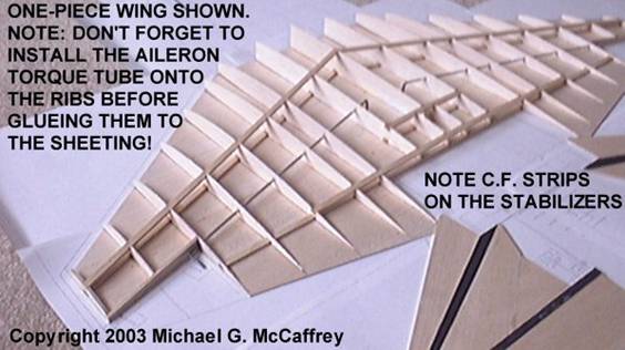
The stabilizer halves are made from 3/32" balsa, with two external spars. Carbon fiber strips (0.007" thick) are glued to the top and bottom surfaces of the stabilizer. See the plan for exact location. Both front and rear spars must be used to insure the strength of the joint between the stabilizers and the fuselage.
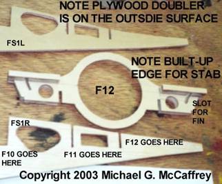
The fins and rudders are made the same way as the stabilizers and elevators. One set of external spars is used for each fin. Note a stub spar is created, by extending the carbon fiber past the bottom edge of the fin. This stub-spar will go into slot in former F12. Do not delete this feature! This is a very strong way of attaching the fins to the fuselage.
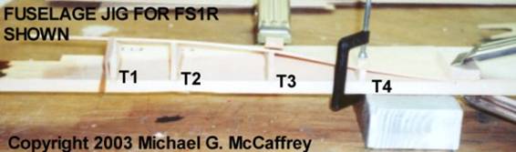
FUSELAGE FORMING TOOL:
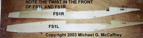
The forward portion of the X-35 fuselage is tricky. In order to transition from the tapered cross-section to a simple box structure required a significant twist in the fuselage sides. I made a jig to help form the fuselage sides FS1L and FS1R. You will need two jigs one for each side. The jigs use the same pieces, but the arrangement of the pieces is such that the tools are mirror images of each other.
T1-T4 are glued to a board per the drawing. The balsa FS1 and the 1/32" plywood doubler are clamped to the jig as shown. Five-minute epoxy or slow cure CA glue can be used. I did not try contact cement, and wouldn't recommend it because you may not get the pieces aligned correctly before the glue grabbed onto the parts. Forming the sides requires the glue to set after the pieces are clamped to the jig. Let the epoxy set up over night.
Once the two sides are formed, the rear plywood doubler can be added. Note it is on the opposite side of the front doubler. There is a slight bow in the very end of the FS1L and FS1R. This can be seen in the drawing. I did not feel a jig was required to form this small bow. Also, note the plywood doublers for the rear landing gear mount. Plywood doublers are added to both sides of the FS1L and FS1R. They are slightly different in shape. The inner doubler goes all the way to the bottom edge, and the outer doubler is shorter.
After FS1L and FS1R are complete, cut out the formers F2 through F12. (There is no F9) Add the engine mount blind nuts to F2, and the nose gear mount to F4. Cut out the front and rear wing mounts from ¼" plywood.
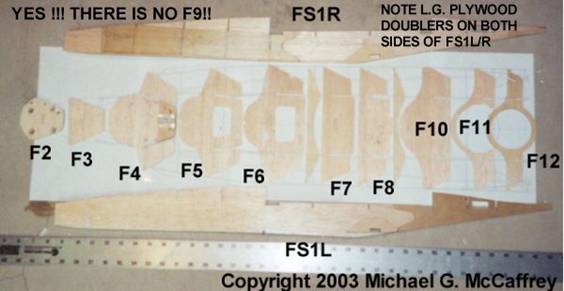
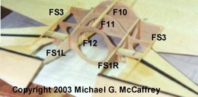
F12 has blocks added to the front and rear to form the rudder stub-spar slot, and to provide a shelf for the stabilizer. There should also be a hole in F12 for the servo connector to go through. Note the hole for the throttle/nose gear servos in FS1L and FS1R. There are also holes for servo wires in FS1L/R
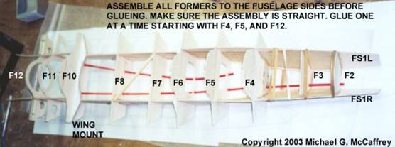
Once the formers are all set, dry assemble all of the former onto FS1L/R. Start at F4 and F5, then add F12. This will hold the two fuselage sides in place. Add the formers F6-F10. Using rubber bands, place F2 between the fuselage sides, and then add F3 in the same manner as F2. Add the wing mounts. With the assembly on the building board, make sure the whole assembly is flat on the table, and square to the drawing. Add a brace (see the one between F7 and F8) as required to keep the assembly square. Once you are sure it is straight, start gluing the former to the fuselage sides. Start at F4, F5 and F12, and end with F2. F2 should be epoxied in. Epoxy the wing mount blocks now.
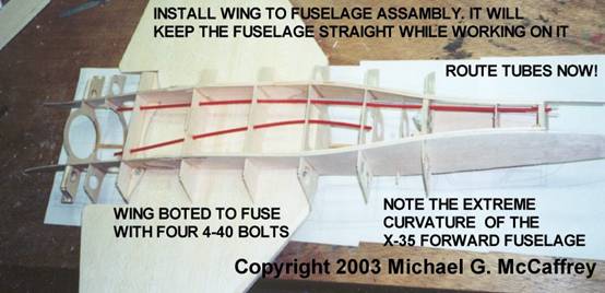
Add the control-rod guide tubes and the fuel lines at this time.
After the fuselage assembly is dry, place the wing into the gap between F6 and F10. Making sure the wing is aligned with the fuselage, drill one mount hole though the wing and wing mount. Remove the wing and add a blind nut to the hole in the wing mount. Bolt the wing in place and drill the next hole. Do this for each hole until you are done. If you do one hole at a time, you are less likely to end up with holes that don't line up.
Now is a good time to add the bottom sheeting between FS1L/R and F2 through F9. I ran the grain across the bottom.
With the wing installed, the fuselage is very stiff. Make sure the bottom still sit flat on the workbench. With the fuselage bottom sitting on the workbench carefully measure the height of each side of F12. Make sure the bottom of the stabilizer shelf is at the same height left to right. Make sure the slots in the rear edge of FS1L andFS1R are the same height.
NOTE: the X-35 has a horizontal stabilizer. The shelf on F12 should be level with the building board, and the height should match the drawing side view.
The F-35 however has a small amount of dihedral in the stabilizer. This makes the checking of F12 a little more difficult. The outside edge of the shelf should be the same height left and right, and the inside edge if the shelf should be the same height left and right, the height will not be the same inside to outside.
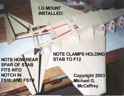
Clamp the stabilizer halves to F12 at the same time. Trim F12 and FS1L/R as required to insure the stabilizers are the same height at the front and rear edges. Make sure the training edges of the stabilizers are level to the table. For the F-35, the angle of the stabilizers, as well as the height from the table should be the same on both sides. Once you are sure everything is right, glue the stabilizers to F12 and FS1L/R.
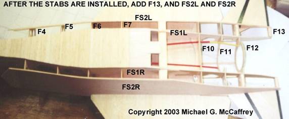
Once the glue is dry on the stabilizers, add FS3 to each side. FS3 is glued to F10-F12, and the top if the stabilizer. At this point, you should add the small F13 former to the bottom of the stabilizers.
Add the formers FT6-FT10 to the top of the wing. Use a scrap piece of 1/16 balsa to create a gap between F6 and FT6 and F10 and FT10. Glue the 3/16" sq. balsa top longeron to the formers running from the front of F4 al the way to F12, in one continuous piece. Use water to help soften the balsa. Do not cut the 3/16 sq balsa between the F6/FT6 and F10/FT10 joint. This will be cut after all of the top sheeting has been added, late in the construction process.
It is time to flip the plane over and work on the bottom sheeting. Glue the main landing gear mount block in the fuselage. Glue a 1/8" sq balsa stringer, running from F4 to F9, to the outside bottom edge of the formers. Add a 1/8" sq balsa stringer from F13 to F10 and continue this stringer to F9. This rear strip is spliced into the stringer running from F4-F9. Using a plane, or hobby knife, bevel the edge of these two stringers to match the outside edges of F4 through F13.
Add a small piece of wood on the bottom side of FS3 between F10 and the leading edge of the stabilizer. You goal is to create a flat surface and fill the gap.
Trial fit the two FS2's (FS2L and FS2R are really identical pieces) After you are sure you have a good fit to the bottom of the wing, and the stabilizer, glue them in place. Note they should fit to the strip of wood added to the bottom of FS3 in the previous step.
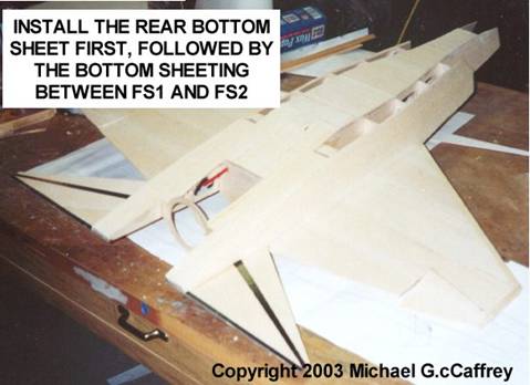
Glue the rear bottom sheet to the fuselage. Note the bottom sheet intersects the bottom of the fuselage near F9 at an angle, and is glued to FS1L/R, FS2, and F9 through F13.
Then glue the forward sheeting to the bottom of F4 through F9, and the LE of the rear bottom sheet. Note the two forward bottom sheets are mirror images of each other, and should be custom fitted to the outside curvature of FS1L/R. Once the forward bottom sheets are glued, trim them flush with FS2.
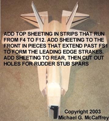
Flip the plane back over, and start sheeting the top of the fuselage with 1/16" balsa. Sheet the top running the balsa from the front (F4) to the rear (F12) and between the inside edges of FS1L and FS1R. The front wing LE extension between F4 and F6 is made one piece of wood extending from the outside edge of FS1L/R past the outside edge of the formers. Sheeting is added between FS1L/R, FS3, and F10 through F13. Then cut a hole through the sheeting at F12 for the fin stub-spars. One the sheeting is installed you can cut the wing away from the fuselage.
|
