How to create and import images for further design work in SketchUp
In order to be able to capture images for use in SketchUp we will first
download and learn how to use a small programme called "Faststone Capture".
This programme is very useful for capturing images - not only for use in
SketchUp, but also in many other software applications. Go to this homepage: https://www.faststone.org/FSCaptureDetail.htm
and download the programme. Once downloaded you install it, and, when
activating you will get a small floating toolbar looking like this ![]() .
.
To begin with we will use only very few of the many features available
in the programme. Let us make a small exercise to see how it works. The programme
works in the way that you select what you want to copy by dragging a frame
across you window in order to define what you want to copy. The button we will
use most frequently is this:![]() .
.
Try clicking on the button and you get a red "cross hair". Click on a start point and drag the frame across the screen and the click on a stop point on your screen. Apparently nothing happens !!!
However, depending on the settings controlled here:
you will get a list of options like these:
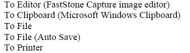
We will use these options for different purposes. Sometimes it is convenient to use the "To clipboard" option. Let us try it now.
Open a site on the internet from where you would like to "steal" an
image. Also open a programme, for example "Word". 10510g61k Now activate Faststone - chose
the "to clipboard" option as referred to above. Next you click on this button ![]() .
.
Go to the internet page and drag a frame across the picture you want to copy - clicking where you want begin and where you want to stop.
Go back to Word. Right click on your mouse and choose "paste". Your picture now appears in word - and you can resize and move it as you like.
We shall now see how we can use the programme for importing images into
SketchUp. The method described above cannot be used in this case. First
we will have to change settings in such a way that we will now save the image
in a file. Click here  and check (select) "To file".
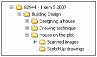
Before we continue, we will need yet some more folders in the folder system which we created at the beginning of the drawing technique course. Go to your own personal drive (the G-drive) and open the folder "House on the plot". Create new subfolders named.
![]()
![]() These are the new folders you are
requested to
These are the new folders you are
requested to
create
Next step, you open "Fronter" and in "week 4" of "House on the plot" you
open the file "Cadastral subdivision with contour lines". Once open, click on ![]() and use "start point" and "end point" as shown
below
and use "start point" and "end point" as shown
below

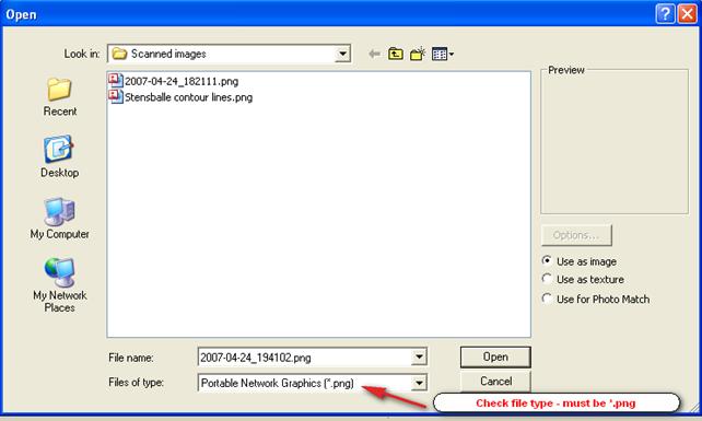
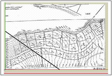
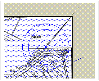
Make sure that the cross frame covers the exact length of the map (450 m). Also make sure to incorporate the "north arrow" as we will need it later. Once you have clicked at the "end point" the programme automatically prompts you to indicate where to save the file and also to give it a name. Name the file "Stensballe contour lines.png" .Navigate to the file "Scanned images". Before you save, make sure that the file is type *.png, (save as type).
We are now ready to import the file into SketchUp.
Open SketchUp.
Click on File->Import
Navigate to your folder "Scanned images" and find the file "Stensballe contour lines". If it does not appear on the list it is because you need to choose the correct file type at the bottom of the pop up window
Click on "open". As insertion point we choose "Origin". Move the mouse
towards the right and watch the VCB (value control box) at the lower right
corner as you move. Enter the length of the map (450 m = 450000 mm). Press
"Enter" and your image is now so big that it looks blurred. An easy way to
resize the image is to click on ![]() .
Try it. The image fits the screen. This is still an image and not a "face" in
SketchUp terms. Try to draw a line across one of the corners as shown below:
.
Try it. The image fits the screen. This is still an image and not a "face" in
SketchUp terms. Try to draw a line across one of the corners as shown below:
The line appears thick and when you click on either side of the line you do not see any difference as you would normally do in a SketchUp rectangle. Draw a small rectangle next to the map in order to test it out. It looks like this when you click on one side or the other:
We would like our map to "behave" in the same way. To do so, place the cursor on top of the map and right click. Choose the option "explode". Now you will see that the line turns thin and if you try to click on either side of it you will notice that the map behaves like a normal SketchUp rectangle, i.e. it is now a "face".
Delete the line you have drawn across the corner. Also delete the small rectangle.
We will now turn our plan to give it the right orientation towards the compass. In SketchUp by default (standard) north is always "up" along the green axis.
 As earlier indicated
we will need the north arrow to perform this action. First "select all", for
example like this: click on Edit-> select all. Next click on
As earlier indicated
we will need the north arrow to perform this action. First "select all", for
example like this: click on Edit-> select all. Next click on ![]() (rotate).
Place the protractor at the beginning of the "north arrow" as shown here:
(rotate).
Place the protractor at the beginning of the "north arrow" as shown here:
Turn the wheel until the dotted line is aligned with the arrow - then
click again. When you turn again the plan will start rotating. Turn slowly
counter clockwise until a small "pop up" reading "On green axis" appears. Then
click. The plan is now oriented towards the compass. Move the plan upwards by
use of the move tool ![]() .
.
Now zoom in and find the plot you have chosen during your visit to the area.
Activate the pencil tool and start by drawing the boundary lines on top of the rough lines on the map (try to start and end lines in the centre of the small circles used as corner demarcations - zoom in until you can see what you are doing). Once you have finished drawing the boundaries and when they are properly connected at all corners, a new face - the plot itself - has been created. You can check this by clicking somewhere inside the plot and you should see the characteristic raster image (small blue dots). We can now check the size of the plot. To do so: Right click (also called "context click") on the plot. Choose the option "Area"-> "Selection". The image could be something like this:
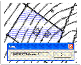
The reading here says 1209997907 Millimeters ²
As we all know: 1 m2 = 1000000 mm2
So, moving the point 6 places to the left gives us an area of 1209.9 m2
Let us compare this figure with the actual size as calculated by the land surveyor (See on Fronter- week 4 - "Plot prices in Stensballe". This is plot no 57 and the poster says 1218 m2. This is very close, and definitely acceptable (only 7 per mille difference).
Next we will draw the contour lines. Select the "Freehand" tool ![]() and start drawing on top of the contour lines on
"your" plot. Make sure to connect the contour lines to the boundary line at
both ends of the line. If you make a mistake, use the "undo" button
and start drawing on top of the contour lines on
"your" plot. Make sure to connect the contour lines to the boundary line at
both ends of the line. If you make a mistake, use the "undo" button ![]() to erase the latest drawn line.
to erase the latest drawn line.
We can now try to raise the terrain. As you already know the level
difference between two contour lines is 500 mm. If we look at this plot
separately we may leave the lowest platform at its current level (level with
the plan). We raise platform no 2 by 500 mm and all the subsequent also by 500
mm in relation to the previous platform. Use the "Push/pull" tool ![]() .
.
Once you have finished you will get an image similar to this: 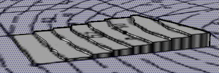
If you really want to make the area look realistic, you should draw up all the contour lines - in this way you can start raising the terrain from the lake shore. That would look great, but it is quite a job to draw all the lines. If you decide to do it, you must make sure that both ends of each contour line is be connected to a "frame", i.e. it cannot end in the middle of nowhere if you want to be able to "pull up" the terrain afterwards.
Once you have completed all the lines. We will leave the plot for a while and begin working on the plan. Save the file in the folder "SketchUp drawings" a give it a name like "Plot no xx with contour lines"
Open up a new file and give it the name: "Plan house type x"(1,2,3,or 4). Save it in "SketchUp drawings"
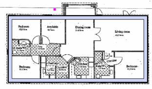
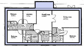
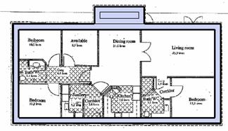
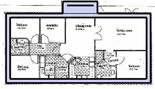
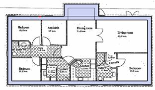
Import the plan using the same procedure as described above. This time
we will use a different scaling method in order to make sure we get the right
dimensions. Import the plan. You may start by placing the first corner at "origin"
as you did above. Move the cursor towards the upper right and click somewhere.
Next you pick the tape measure tool ![]() and measure the length of a façade wall. The
measurement appears in the VCB. No matter what the reading says - your next
step will be to enter the correct length of the wall (you can find that by measuring
on the paper version of your plan using your conversion ruler. Once you have
entered the value, press "enter" and you will see this "pop up"
and measure the length of a façade wall. The
measurement appears in the VCB. No matter what the reading says - your next
step will be to enter the correct length of the wall (you can find that by measuring
on the paper version of your plan using your conversion ruler. Once you have
entered the value, press "enter" and you will see this "pop up"
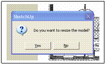
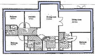
Click on "yes" and your drawing is scaled to correct dimensions - check them!!!
In the following chapter we will look at different ways of drawing the plan on the basis of the imported image.
This time we will try to work with the plan as an "underlay drawing", i.e we will not turn the drawing into a face by exploding it like we did with the plan of the area in Stensballe.
This means that we will start drawing right away. Let us first try to concentrate on he external walls - without windows or doors.
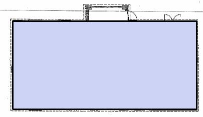
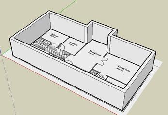
Start by drawing a rectangle covering the main part of the building and following the outside of the external wall. The image should look similar to this
Choose the offset tool ![]() and click once somewhere on the blue face. By
moving the cursor right or left we get two differently shaped rectangles inside
the blue rectangle already drawn. Moving left, we get a rectangle of the same
orientation as the blue rectangle, and moving right we get a rectangle
perpendicular to the blue rectangle. Now, move right and by entering a value in
the VCB we can decide what should be the distance between the two rectangles.
In this case we will define the exterior wall as 348 mm thick, so we write 348
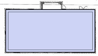
in the VCB and press enter. Your new image looks like this:
and click once somewhere on the blue face. By
moving the cursor right or left we get two differently shaped rectangles inside
the blue rectangle already drawn. Moving left, we get a rectangle of the same
orientation as the blue rectangle, and moving right we get a rectangle
perpendicular to the blue rectangle. Now, move right and by entering a value in
the VCB we can decide what should be the distance between the two rectangles.
In this case we will define the exterior wall as 348 mm thick, so we write 348
in the VCB and press enter. Your new image looks like this:
Context click (right click) somewhere in the central part of the blue rectangle to invoke a submenu. On this submenu choose "Erase". Your drawing now looks like this:
We have now managed to draw the external wall, but we have problem: We can no longer see the position of the windows, but don't worry we will solve the problem in due course.
I you have any building additions (like we have in this case) you should also draw a rectangle covering such parts of the building - like shown below
Use the Offset tool ![]() again
and offset the small rectangle - again by 348 mm, like this:
again
and offset the small rectangle - again by 348 mm, like this:
Now, invoke the eraser tool ![]() and erase three of the four sides in the
latest drawn rectangle like this:
and erase three of the four sides in the
latest drawn rectangle like this:
Next you connect both ends of the remaining line to the external side of the first rectangle like this:

Extent these lines further to reach the innermost rectangle as shown here:
Again, invoke the eraser and remove these lines:
Try to rotate the plan - press the mouse wheel and rotate - or click on
view "iso" ![]()
Your plan looks like this:

Invoke Push/pull (press "p") and try to push up the wall.
Press "undo" followed by "top view" to return to the previous situation.
We will now start drawing the internal walls, but before we do so, we will have a look at another important feature which makes SketchUp models very illustrative. The feature is called "Layers". Imagine you can hide the things you have already drawn and recall them again whenever you want to. This could be very useful, for example if you draw the entire house with roof and everything and later on you would like to hide (actually remove) the roof in order to give a view of the interior. This is actually what we do when we draw in layers. We make it possible to hide and recall elements or components whenever we want to. Now, the important thing is to keep track of what we have hidden, and where we have hidden it. SketcUp has created a system to be used for this purpose. Each thing (component, element etc) we want to hide/recall is called a layer. Therefore, we will name the layers after the things hidden in them. Let us now try to create a layer for the external wall which we have just drawn.
First activate the toolbar
"Layers". Click View->Toolbars->Layers. This it what it looks like:  .
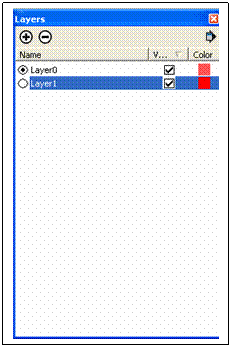
You will notice that we already have a layer called "Layer0". This layer is
always there by default and in case we choose not to make additional layers,
all the entities of the drawing will be placed in this layer and we will not
have a chance of hiding single elements. The layer displayed in the small
window is called the active layer. So, by default, "Layer0" is the active
layer. The active layer cannot be switched off. Try clicking on the
small arrow next to Layer. You will find that also "Layer1" has been defined.
Try to click on it and you will notice that "Layer1" now becomes the active
layer (displayed).
.
You will notice that we already have a layer called "Layer0". This layer is
always there by default and in case we choose not to make additional layers,
all the entities of the drawing will be placed in this layer and we will not
have a chance of hiding single elements. The layer displayed in the small
window is called the active layer. So, by default, "Layer0" is the active
layer. The active layer cannot be switched off. Try clicking on the
small arrow next to Layer. You will find that also "Layer1" has been defined.
Try to click on it and you will notice that "Layer1" now becomes the active
layer (displayed). ![]() We
will now try to switch off Layer0 (since it is no longer the active layer we
can do so). Click on the
We
will now try to switch off Layer0 (since it is no longer the active layer we
can do so). Click on the ![]() next
to the layer name and this box appears:
next
to the layer name and this box appears:
 We now get an overview of the layers created and we
can also see, whether they are switced on or not. The checkmark indicates that
a layer is switched on. Try now to uncheck "Layer0" and notice what happens. The
entire drawing should dissapear.
We now get an overview of the layers created and we
can also see, whether they are switced on or not. The checkmark indicates that
a layer is switched on. Try now to uncheck "Layer0" and notice what happens. The
entire drawing should dissapear.
So far "Layer1" is not being used for anything. We will rename this layer and use it for our external walls. Click on the name and overwrite it with "External walls" to make it look like this:
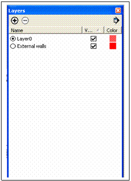
What is remaining now is to define the components belonging to this layer and to place them in the layer.
Follow these steps to do so:
Select the external wall only (use select tool)
Click on "Window"-> Entity Info
Find External walls on the list of layers and close
the window again by clicking on ![]()
Now make "Layer0" the active layer (on the layer toolbar)
Click on the ![]() icon
on the layer tool bar and uncheck "External walls". The walls will now
disappear from the drawing. Check "External walls" again and the walls
reappear.
icon
on the layer tool bar and uncheck "External walls". The walls will now
disappear from the drawing. Check "External walls" again and the walls
reappear.
In stead of defining a layer after we have drawn a certain item it is much better to define the layers first (before drawing). All we have to do then is to make a certain layer active before we start drawing and we will not have to worry about including the right things in the layer. This method has also proven useful because it is sometimes difficult to say whether a certain line belongs to one element or another.
So, before we continue drawing, we will define some of the layers that we will need immediately.
These layers could be:
Internal walls
Windows
External doors
Internal doors
Sanitary appliances
Kitchen units and fixed furniture
Furniture
Roof
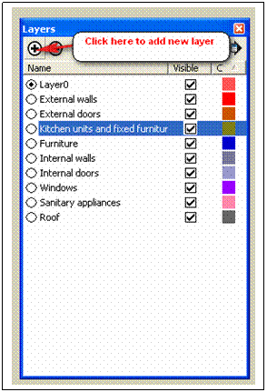
Add these layers to the list one by one by clicking the + button as shown here.
Acivate the "Internal wall" layer and start drawing internal walls.
|
