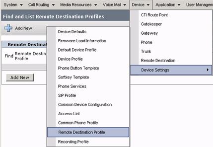
Cisco Unified Communications Manager Business Edition 6.0
Rolling Thunder II
Virtual Hands-on-Lab
Lab Objective: To gain experience installing CUCMBE, configuring call processing, hunt groups, Cisco Unity Connection, Cisco Attendant Console, Mobility as well as viewing real time reporting information using the Real Time Reporting Tool (RTMT).
Please note: Due to the labs being hosted on remote equipment not all components configured within the lab environment can be tested.
Browser Requirements: The recommended browser for this lab is Microsoft Internet Explorer 6. If you are accessing Gold Labs (LabOps) with IE7 please drop the security level of the browser, add the student URL into the list of trusted sites, ensure that pop ups are not being blocked, run the Active X control when requested, and run the Telnet Fix offered on the Topology page. Restart IE7 after making these changes. The labs cannot be accessed via Firefox/Mozilla.
Table of Contents
CUCMBE - Installation / Configuration
Task 1 - Log into Windows XP Workstation 1 and initialize the installation process for CUCMBE
Task 2 - Completing the installation process of CUCMBE
Task 3 - Connect to the Unified CM Administration Interface
Task 4 - Viewing updated menus in Cisco Unified CM Administration 6.0
Task 5 - Configuring Call Control with CUCMBE
Task 7 - Enable Auto Registration
Task 8 - Register Phones with Communications Manager
Task 10 - Hunt Group Softkey Configuration
Task 11 - Audio Notification of Message Waiting Indication
Task 12 - Configuration of Monitor and Recording Features
Task 14 - Advanced Ad-Hoc Conferencing
Task 16 - Create Partitions for Devices and Voicemail Usage
Task 17 - Create Calling Search Spaces for Devices and Voicemail Usage
Task 18 - Create Users for Voicemail and Phone Assignments
Task 19 - Voice Mail Port Setup
Task 20 - Line Group and Hunt List Setup
Task 21 - Message Waiting Indicators
Task 22 - Voicemail Pilot Configuration
Task 23 - Voicemail Profile Configuration
UCM Integration to Unity Connection
Task 24 - Verify Unity License Files
Task 25 - Configure Port Group
Task 26 - Restart Unity Conversation Manager Service
Task 27 - Configure Phone Settings for Voicemail and Associate Users
Task 28 - Enable Voicemail User settings in Unity Connection
Task 29 - Verify Unity Connection Configuration
Task 30 - Configuring Phone View
Task 31 - Configure the IP phone for Phone View
Task 32 - Enable Phone View on User
Cisco Unified Attendant Console
Task 34 - Attendant Console Configuration
Task 35 - Configuring an Attendant Console User
Task 36 - Enabling Device Security for Cisco Unified Communications Manager Attendant Console
Task 38 - Configuring Pilot Points
Task 40 - Configuring Hunt Groups
Task 41 - Cisco CallManager Attendant Console Server Service Configuration
Task 42 - Creating and Uploading the Corporate 737b14h Directory.txt File
Task 44 - Configuring Cisco Unified Communications Manager Attendant Console Settings
Task 45 - Repeat tasks 43 and 44 on Workstation 2.
Task 46 - Test the Circular Hunting functionality of the Attendant Console
Task 47 - Change the Queue from Circular Hunting to Broadcast Queue
Task 48 - Using the Cisco RTMT Tool
Task 47 - Viewing the System Summary
Task 49 - View Server Statistics
Task 50 - Viewing Performance Evaluation
Task 52 - Configuring Unified Mobility and Mobile Voice Access
Task 53 - Mobile Voice Access and Enterprise Feature Access Phone Configuration
Verify Mobility by running a trace with RTMT
Task 54 - Create an H323 gateway
Task 55 - Create a Route Pattern
Task 56 - Set Tracing Parameters
Task 57 - Populate Trace information by making phone calls
Task 58 - View trace information with RTMT
Step 1: Login in to LabOps using the following URL: https://labops-out.cisco.com/labops/ilt/default.asp
 Step 2: Under
the Access Lab column click on the Access button.
Step 2: Under
the Access Lab column click on the Access button.

 Step 3: Under the Topology tab click on the Device Access button.

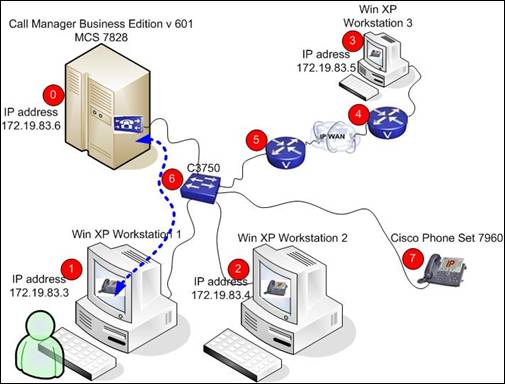
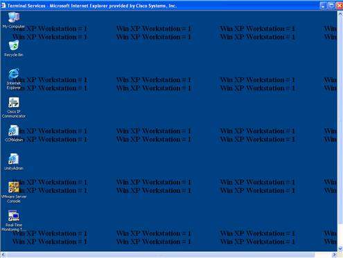
A new browser window will open displaying the lab network diagram. This is an interactive portal giving access to each of the Workstations. Please access the workstations when instructed to do so in the lab guide.

![]() Step 4: Point and
click in the center of Workstation 1's
screen. A Terminal Services bar will
appear.
Step 4: Point and
click in the center of Workstation 1's
screen. A Terminal Services bar will
appear.
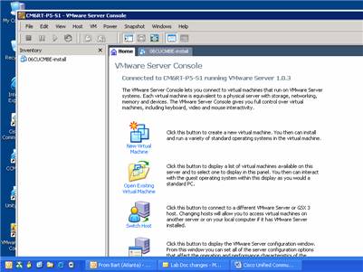
Step 5: Click on the Terminal Services bar to initiate a remote desktop session to the Windows XP Workstation 1. The screen below will appear.


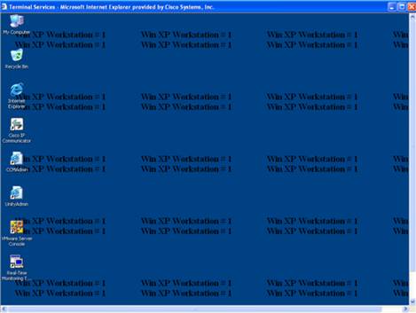
Step 6: Locate the VMware Server Console icon  and double click on it. The window pictured
below will appear.
and double click on it. The window pictured
below will appear.
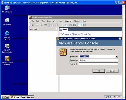
Step 7: Verify that the connection is to IP Address 172.19.83.2.
Step 8: Enter username Student, password test$1234
Step 9: Press Enter.
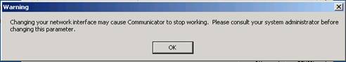
Step 10: If this message box appears, click OK.
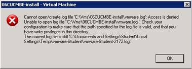
Step 11: The following screen will appear. Click once on 06CUCMBE-install to bring the focus to the image.
![]()
 Step 12: Click on the
green arrow to start the image.
Step 12: Click on the
green arrow to start the image.
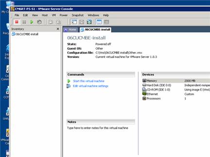
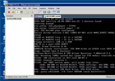
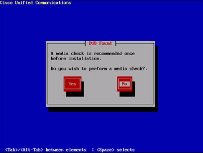
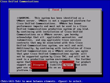
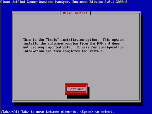
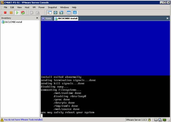
This will automatically launch the installation disk on the Cisco MCS server. This screen will appear.
CUCM Business Edition is being installed from a server. This server is indicated in the network diagram with a red circle labeled '0'. For the purposes of this lab the mechanical process of putting the DVD in a physical drive is circumvented through the use of the VM Ware software. The screens and processes that will be followed in this lab will mirror the Communications Manager Business Edition DVD installation process.
Step 1: Once all the text stops moving, the installation screen will appear. At this point the mouse is not supported so the navigation arrows of the laptop keyboard need to be used.
Note: On an IBM laptop these will be below the Enter key
 Note:
Navigation will be a little tricky here. Make sure to click once on the blue
back ground to bring the keyboard focus to the correct screen.
Note:
Navigation will be a little tricky here. Make sure to click once on the blue
back ground to bring the keyboard focus to the correct screen.
Step 2: Choose the NO option and press the Enter key.
Step 3: The following screen will appear. Use the arrow keys of the laptop to choose Agree. Press Enter.
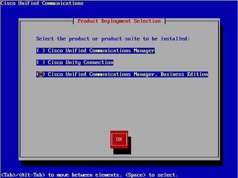
Step 4: The next screen will bring up the option for installing the Cisco Unified Communication Manager, Business Edition. Navigate and choose Business Edition (using the space bar to mark this version for the installation) click OK and press Enter to continue.
Note: Use the up - down keys and the space bar to make selections. Use the tab button to move on to the OK button.
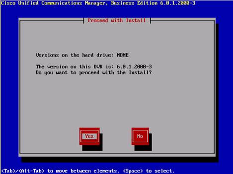
Step 5: To continue with the version on this DVD, select Yes and press Enter to proceed with the installation
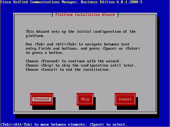
Step 6: Select Proceed and press Enter
Step 7: Press Enter to continue
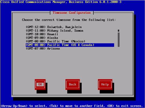
The screen below is very similar to the screen presented when setting up regular Communications Manager 6.0. The only difference is that with CUCM Business Edition, Unity Connection will install behind the scenes.
Step 8: Select the time zone using . Use the TAB button to move the cursor to OK and press Enter.
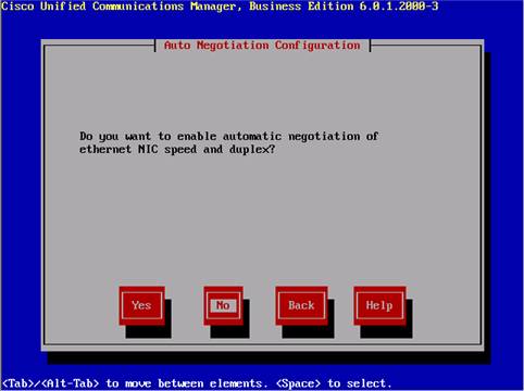
Step 9: The Cisco install documentation recommends that auto negotiation be disabled. Select No and press Enter.
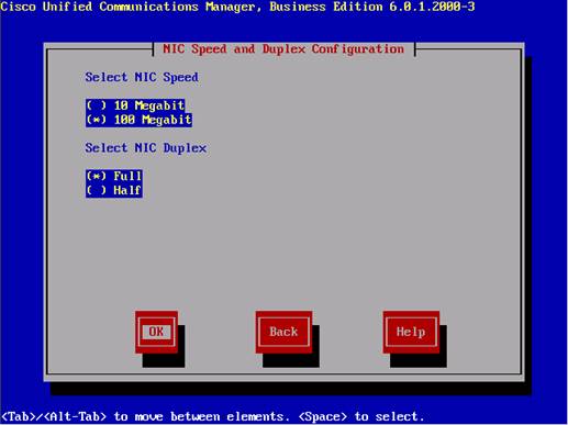
Step 10: Select the 100 Megabit and Full duplex options. Select OK.
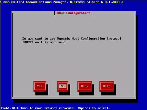
Step 11: Select No for DHCP
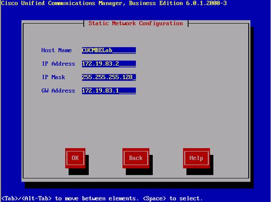
Step 12: Enter the Host name, IP address, IP mask, and default gateway address based on the information seen in this screen shot. Select OK and press Enter
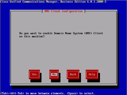
Step 13: Disable DNS
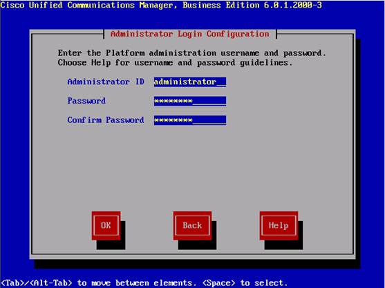
Step 14: Set Admin Rights (username administrator, password C1sco123)
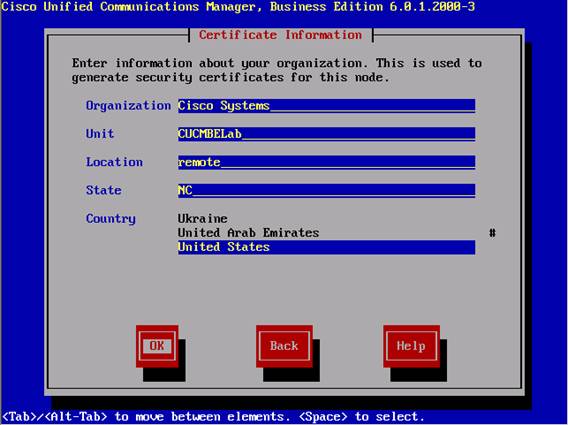
Step 15: Input the Certificate Information as seen in this screen shot.
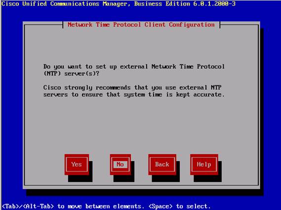
Step 16: Disable NTP
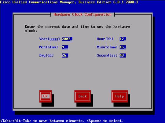
Step 17: Configure Date and Time
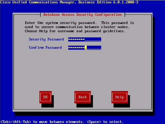
Step 18: Set Security Password - use C1sco123
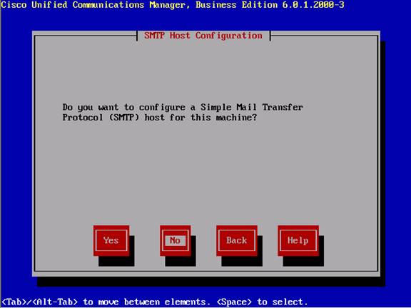
Step 19: Disable SMTP Services
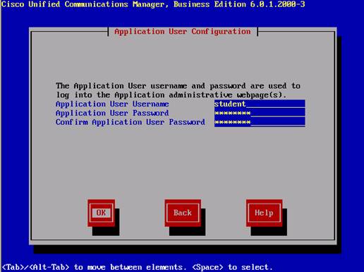
Step 20: Enter Application User Information (username student, password C1sco123)
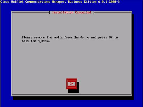
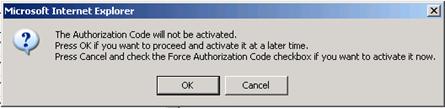
Step 21: This is the point at which the software would normally be installed. DO NOT CLICK OK!
Step 22: Click Cancel.

Step 23: Click OK.
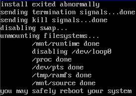
The system will identify that the install is exited and will shut down. Once the message 'you may safely reboot your system' proceed to Step 24.
Step 24 Press Ctrl-Alt to bring the focus back to the mouse.

![]() Step 25: Click the red button to stop the VMWare image. Once the image has shut down, close the VMWare server console window
Step 25: Click the red button to stop the VMWare image. Once the image has shut down, close the VMWare server console window
This portion of the lab in now complete.
Please continue with the next task.
Access the administration page through the web interface.
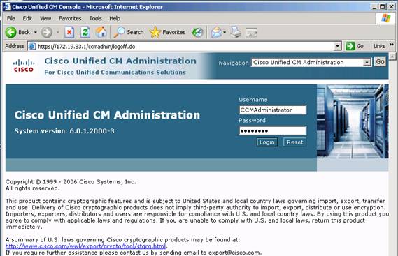
Step 1: Access the Cisco Unified Communications Manager 6.0 Administration page by clicking the Internet Explorer icon on the desktop that is labeled CCMAdmin.
Note: To access the Cisco Unified Communications Manager 6.0 administration page, Microsoft Internet Explorer is required.

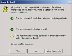
Step 2: Click Yes to accept the SSL Security Certificate.
Step 3: Login with username "CCMAdministrator" and password "C1sco123".
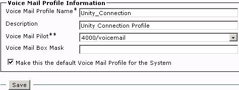
![]()
This task is completed when this result is attained:
Cisco Unified CM Administration Pages can be viewed.
Note: To improve Communications Manager GUI navigation when using LabOps with a smaller screen, scroll to the right of the Communications Manager GUI and maximize the IE screen as shown below. Use the right and lower scroll bars to navigate the entire Communications Manager GUI screen
Step 1: Go through the menus on the Unified CM Administration Page to get familiar with the menu layouts.
Note: To view any of the submenus hover over the main menu item with the mouse.
Step 2: Note any differences or additions in the menus from previous versions of the Communications Manager appliance.
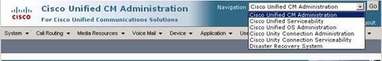
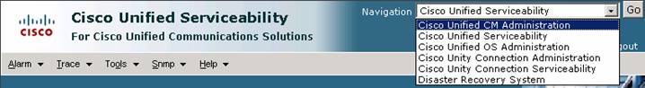
Note: Navigation from Unified CM Administration to Unified Serviceability or to Unity Connection is done via selecting the module from the drop down list at the top right hand corner and clicking Go.
![]()
This task is complete when this result is attained:
Reviewed all the menus in Cisco Unified CM Administration Page.
This module will show the configuration steps necessary to enable essential services and configure call control within CUCMBE
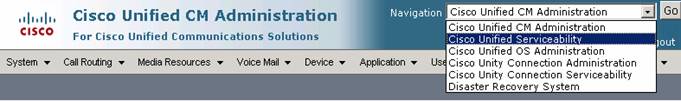
Step 1: Select Cisco Unified Serviceability from the Navigation panel and then click Go.
![]()
Step 2: Select Tools/Service Activation
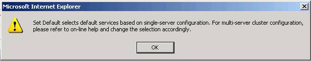
Step 3: Make sure 172.19.83.1 is selected, Click Set to Default

Step 4: A pop up box will open, click OK
Step 5: Select Cisco Unified DHCP Monitoring Service, and IP Voice Media Streaming Application.
![]()
![]()
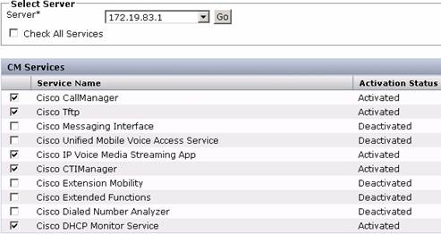
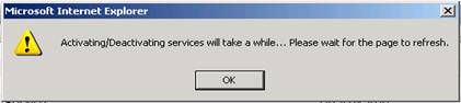
Step 6: Click Save.
Step 7: Another pop up box will open, click OK
Step 8: Select Tools /
![]()
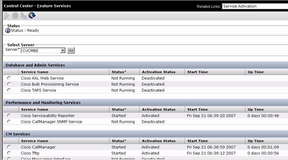
Essential Call Control Services are now enabled.
Do not log out. Continue on with Task 6.
Step 1: From the Navigation drop down list select Cisco Unified CM Administration and click Go
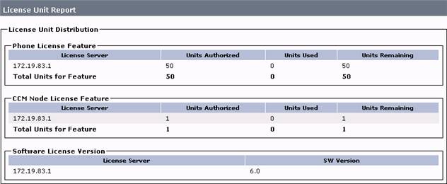
Step 2: From the System menu, Select Licensing (it's right at the bottom) License Unit Report and verify that there are enough units remaining.
![]()
Continue on with Task 7.
Step 1: Select System Cisco Unified CM
Step 2: Click on Find
Step 3: Click on CM_CUCMBE
![]()

Step 4: Under Auto-Registration Information, type 1001 as Starting Directory Number
Step 5: Under Auto-Registration Information, type 1009 as Ending Directory Number (disregard any Invalid Range Warnings)
Step 6: Ensure that the Auto-Registration Disabled box is NOT checked
Step 7: Click Save


Do not log out. Continue on with Task 8.
Task 8 - Register Phones with Communications Manager
Note: Further on there will be a requirement to initiate a remote desktop sessions to Workstations 2 and 3. Do not launch these until requested to do so.
Step 1: Minimize the Cisco Unified CM Administration screen to view the desktop of Workstation 1.
Step 2: From the Workstation1, double click on the Cisco IP Communicator icon to launch the application.

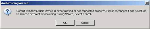
Step 3: If requested, click Cancel to force the Tuning Wizard to launch.

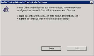
Step 4: If requested, step through the Audio Tuning Wizard (keep default settings) to complete the application launch.

Step 5: Close Cisco IP Communicator and launch it a second time. When used inside Terminal Services, this pre-release beta version of the product typically requires a restart to perform correctly. When re-launching, there may be a requirement to go through the tuning process again since the connection utilized here is a remote one. This should be the resulting screen (the extension may be different).

Note: IPC may not register with an extension or with the correct MAC address. Follow these troubleshooting tips to resolve these issues.
![]()
![]() Step 5.1: From
the Menu drop down select Preferences
Step 5.1: From
the Menu drop down select Preferences
![]()

Step 5.2: Select the Network Tab at the top
A. Select the VMWare PCI Ethernet Adapter #2 from the drop down list as the Network Adapter
If this message appears - Click OK
B: Change the IP address of the TFTP server to 172.19.83.1 and remove any references to a second TFTP server.


Step 5.3: Click OK
Step 5.4: Shutdown and restart the IP Communicator.
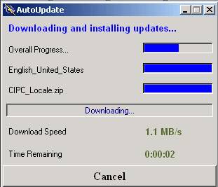
This window may appear showing software auto update for the IP Communicator. This is normal behavior.
Step 6: Turn the audio volume up on the PC or laptop. Leave the terminal session open.
Note: The sound from remote desktop is going to be forwarded to the laptop.
Step 7 Now connect to Workstation 2 via the LabOps topology page.
Step 8: Once connected, launch IP Communicator and complete the steps as described in steps 1 though 4 above. Leave the terminal session open.
Step 9: Now connect to Workstation 3 via the LabOps topology page.
Step 10: Once connected, launch IP Communicator and complete the steps as described in steps 1 though 4 above. Leave the terminal session open.
Step 11: On Workstation 1, if not already logged in, login to CUCM Administration.
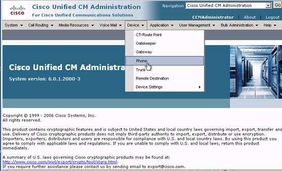
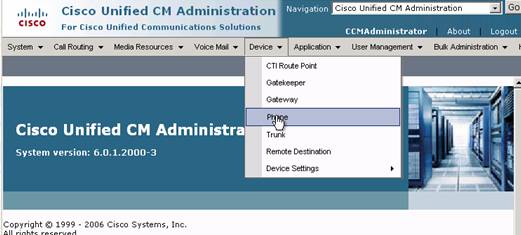
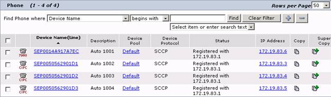
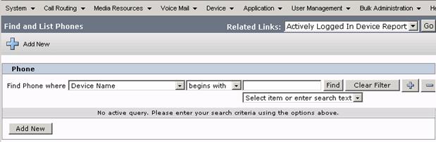
Step 12: From the Device menu select Phone
Step 13: Click Find to query the database for an existing extensions list.
![]()
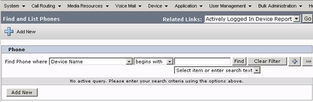
Three IP Communicator phones should be listed as well as a hard phone (7960). (Device names may not be exactly as shown on the next page.)
Step 14: Verify that phone calls can be made between all of the workstation phones.
Note: This is a new version of IP Communicator. Any issues encountered with the application, such as not responding, may require quitting the application and re-launching it.
This task is complete when these results are attained:
Three workstation phones are registered with Communications Manager.
Calls can be made between the workstation phones.
All of the workstation phones are to be part of a broadcast hunt group. When the Hunt Group Logout feature is configured, users can log out of hunt groups and temporarily block hunt group calls from ringing their phone when they are not available to take calls. When a user logs out of their hunt groups, it does not prevent direct (non-hunt group) calls from ringing their phones.
Step 1: Go to Call Routing Route/Hunt Line Group
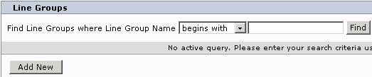
Step 2: Click Add New
Step 3: Name the Line Group HG_2000
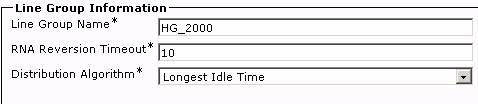
Step 4: Select all IPC extensions
Step 5: Click Add to Line Group
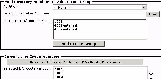
Step 6: Click Save
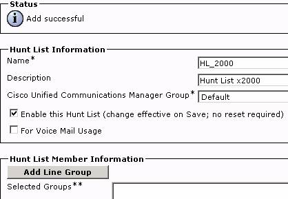
Step 7: Go to Call Routing Route/Hunt Hunt List

Step 8: Click Add New
Step 9: Name the list HL_2000
Step 10: Choose the Default Call Manager Group
Step 11: Check the box Enable the Hunt List
![]()
![]()
![]()

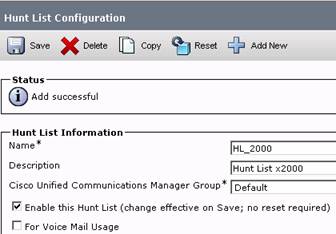
Step 12: Click to save
Step 13: When the screen refreshes, click on Add Line Group
![]()

Step 14: Choose HG_2000 from drop down list
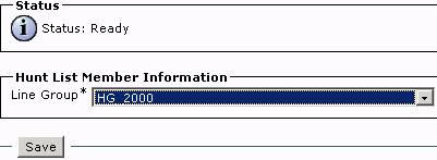
Step 15: Click Save
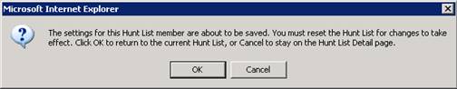
Step 16: Click OK to reset Hunt List
Step 17: Click Reset

Step 18: Click Reset again
Step 19: Click close
Step 20: Go to Call Routing Route/Hunt Hunt Pilot from the main menus

Step 21: Click Add New
Step 22: Use 2000 for the pilot
Step 23: Select HL_2000 from drop down
Step 24: Uncheck provide outside dial-tone
Step 25: Check Personal Preference for forward Hunt No Answer and Forward Hunt Busy
![]()
![]()

![]()
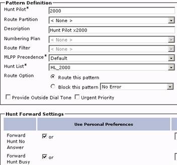
Step 26: Click on Save
Add the "Hlog" softkey to the Workstation 3 device.
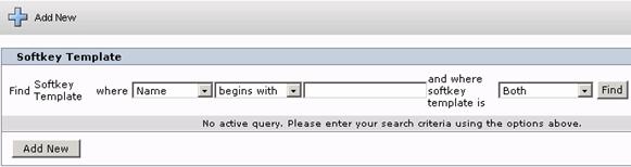
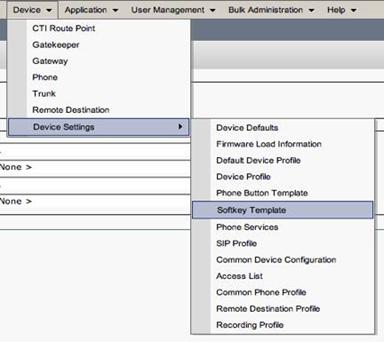
Step 1: From the Main Menu select Device Device Settings Softkey Template.

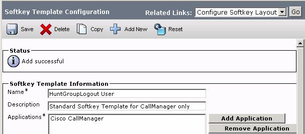
Now create a new softkey template "HuntGroupLogout User" based on the "Standard User" softkey template and add the "Hlog" button to the "On Hook" call state by doing the following:
Step 2: Click on Add New

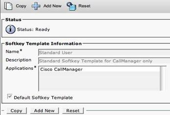
Step 3: Select Standard User
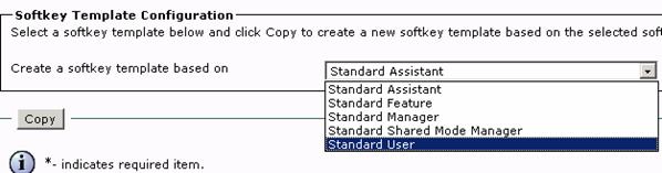
Step 4: Click Copy
Step 5: Type in the new name of "HuntGroupLogout User"
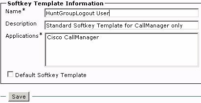
Step 6: Click Save
Step 7: Return to Configure Softkey Layout by clicking on the Related Links: Go button.

Step 8: Find and double click on HLog Softkeys Item on the left side. It should "jump" over to the Selected Softkeys box on the right.
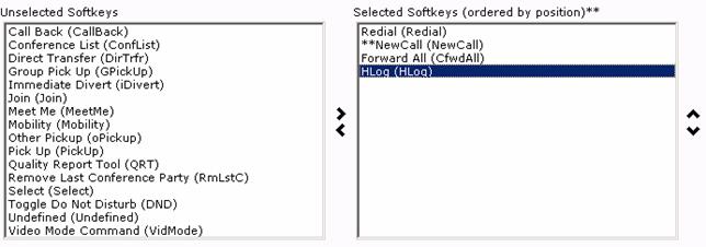
Step 9: Click Save
Step 10: Go to the list of phones by selecting Device Phone from the main menu. (Click the Find button if there are no phones listed.)
Step 11: Select Workstations 3's phone.
Step 12: Apply the "HuntGroupLogout User" Softkey template to Workstations 3's IP Communicator device configuration.
![]()
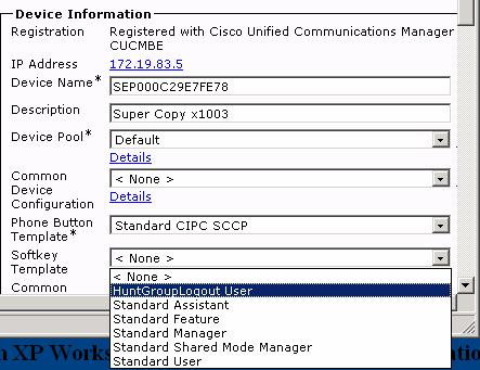
Step 13: Click Save.
Step 14: Click on Reset. In the next window click Reset again. Click Close to close the Reset window.
 Step 15: On
Workstation 3 if IP Communicator is
running it may be necessary to re-launch the application for the change to take
effect. When it completes reloading, the
new softkey HLog button should appear.
Step 15: On
Workstation 3 if IP Communicator is
running it may be necessary to re-launch the application for the change to take
effect. When it completes reloading, the
new softkey HLog button should appear.
![]()
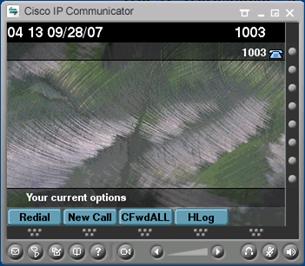
Step 16: Test the hunt group. Dial extension 2000 from any of the three phones. All three phones should ring.
Step 17: On Workstation 3's IPC , press the "Hlog" softkey. A message should display on the status line of this phone indicating that it is logged out of its configured hunt groups.

![]()

Step 18: From either Workstation 1 or Workstation 2's phones, call the hunt group at x2000. Verify that Workstation 3's phone does not ring as part of the hunt group.
Step 19: From either Workstation 1 or Workstation 2's phones, call Workstations 3 directly. Verify that this phone can be called directly even when logged out of the hunt group.
Activity Verification
This task is complete when these results are attained:
All three phones ring when calling the hunt group.
Workstation 3 IPC is able to log out of the hunt group and no longer receive hunt group calls.
Troubleshooting Tips
n If the new softkey template does not appear on Workstation 3's IPC, try exiting the softphone and launching it again.
n Make sure the phone protocol is SCCP. ( SIP phone might not work)
n If the template still does not appear on the phone, try disabling Extension Mobility on that device and resetting it.
Note: This feature cannot be tested with this lab configuration because this exercise is configured on a hard phone which is not local to the PC. Therefore the audible notification cannot be heard.
In Cisco Unified Communications Manager 6.0, phones will support an accessibility feature for visually impaired users who are unable to use the phone's visible message waiting indication (light). This is done by providing an audible message waiting tone, commonly referred to as stutter dial tone. Note that currently Audible MWI is not configurable on IP Communicator.
Create a SCCP 7971 phone
Step 1: From the main menu select Device Phone
Step 2: Click Add New.
Click on
either Add New![]()

![]()
![]()
Step 3: Select the Phone Type: Cisco 7971 from the drop down list.

Step 4: Click Next.
Step 5: Select SCCP as the device protocol.
Step 6: Click Next. If an "Unmapped Exception null" error message appears, simply hit the next button to continue.
Step 7: Use MAC Address 111213141516.
Step 8: Select the Default Device Pool
Step 9: Select Default 7971 button template.
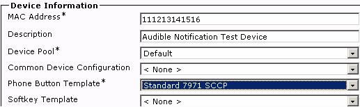
Step 10: Select Cisco 7971 Standard SCCP Non-Secure Profile (Scroll down to set this parameter).

Step 11: Click Save
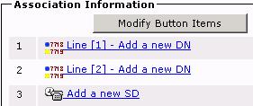
Step 12: Configure the first line on the phone with directory number 1005. On the left side of the screen click on Line [1] - Add a new DN.
![]()
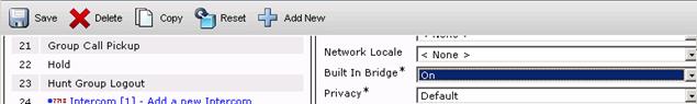
Step 13: Change the "Audible Message Waiting Indicator Policy" to "On.". Scroll down the page to find this parameter.
![]()
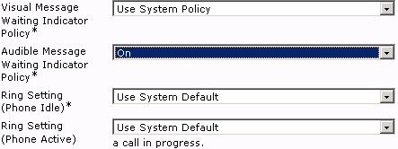
Step 14: Click Save.
Note: The system default can also be set to turn on audible message waiting for anyone with the "Audible Message Waiting Indicator Policy" set to "Default."
Activity Verification
This task is complete when these results are attained:
The "Audible Message Waiting Indicator Policy" for the added Cisco IP Phone 7971 is set to on.
This feature cannot be tested remotely.
Before Cisco Communications Manager 6.0, nearly all recording and monitoring solutions required the use of SPAN and RSPAN to send the audio stream to the monitoring or recording device. Drawbacks of this approach are that SPAN and RSPAN are complex to configure, often requiring site specific equipment, does not scale well, typically forces supervisors to listen to monitored and recorded calls through their pc; it also lacks call admission control or region-based codec negotiation.
Communications Manager 6.0 offers a solution where the phone actually creates a second (IP/RTP) media stream to the monitoring or recording device using the phone's Built in Bridge (BIB). This solution is easier to manage, scales well, and is under the full control of Communications Manager. Depending upon the application (monitoring or recording), the phone mixes both the local and remote side of the conversation into a single IP/RTP stream (for monitoring) or sends the local and remote audio in two separate streams (or recording-this is sometimes referred to as "stereo" or "unadulterated" recording).
Monitoring and recording are both invoked through CTI (JTAPI/TAPI) and have no perceptible effect on the agent or customer's visual display. Because of the way the BIB is used, this feature is only supported on 3rd-Generation phones (7911, 7931, 7941, 7961, 7970, and 7971). For legal compliance, an explicit notification-in the form of a periodic tone-can be made audible to the agent, to the customer, or to both parties to indicate a monitoring or recording session is in progress.; the tone can also be disabled.
Recording uses a SIP trunk between the cluster and the recording device. Call data provided in the SIP header is GlobalCallID, DN and Phone Display Name. Other call specific data can be retrieved via CTI using the GlobalCallID.
Where Monitoring and Recording is continued to be used:
Call centers need to be able to guarantee the quality of customer service that an agent in a call center provides. To protect themselves from legal liability, call centers need to be able to archive agent-customer conversations.
The Silent Call Monitoring feature allows a supervisor to eavesdrop on a conversation between an agent and a customer without allowing the agent to detect the monitoring session.
The Call Recording feature allows system administrators or authorized personnel to archive conversations between the agent and the customer.
Cisco Unified Communications Manager supports the Silent Call Monitoring and Call Recording features only within a single cluster.
The Silent Monitoring and Call Recording features specify generic features in Cisco Unified Communications Manager. Cisco makes these features available to any deployment or installation where monitoring- and recording-enabled applications are available.
In
the following steps, using a fictitious 7971 IP phone, monitoring and recording
will be configured.
Complete these steps to configure Silent Monitoring:
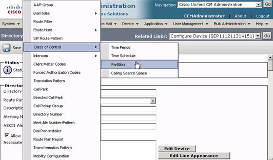
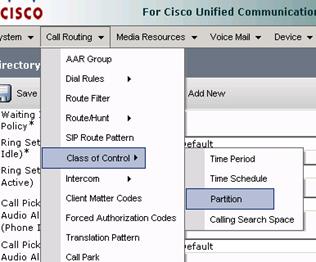
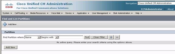
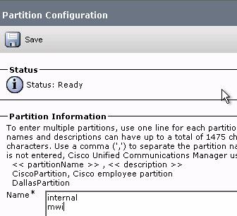
Step 1: From the main menus select Call Routing Class of Control Partition
Step 2: Click Add New
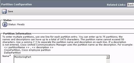
Step 3: Create a "MonitoringPart" Partition
![]() Step 4: Click Save.
Step 4: Click Save.
Type the
new partition in this space.![]()
![]()
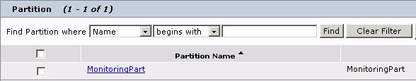
Step 5: In the Find and List Partitions page, select the newly created partition to view it.
![]()
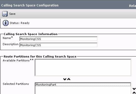
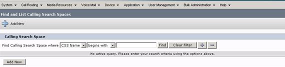
Step 6: Now select from the Call Routing main menu, Class of Control Calling Search Space to create a Calling Search Space called "MonitoringCSS".
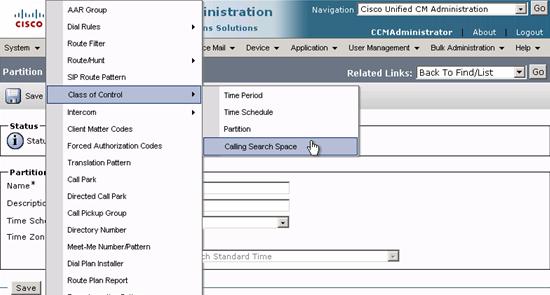
Step 7: Click Add New
Step 8: Call it "MonitoringCSS"
Step 9: Associate it with "MonitoringPart" Partition. This will be used to control who can monitor (or "listen in on") whom.
![]()
![]()
Step 10: Click Save.
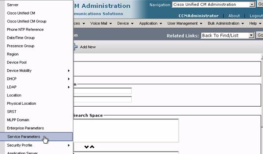
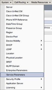
Step 11: Provision two cluster-wide "Monitoring Tone" Service Parameters by selecting System Service Parameters
Step 12: Select 172.19.83.1
Step 13: Select Cisco CallManager
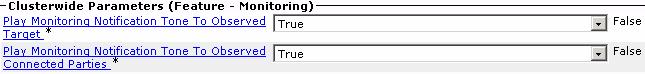
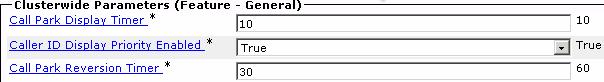
Step 14: For the Clusterwide Parameter (Feature - Call Monitoring), set the "Play Monitoring Notification Tone to Observed Target" parameter to "TRUE". (This parameter is approximately 2/3 of the way down on the page.)
Step 15: For the same Clusterwide Parameter set the "Play Monitoring Notification Tone to Observed Connected Parties" to "TRUE."
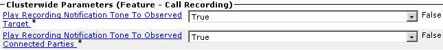
Step 16: As Recording will be configured after Monitoring is configured under Feature - Call Recording set the 'Play Recording Notification Tone to Observed Target' parameter to True.
Step 17: For the same Clusterwide parameter set the 'Play Recording Notification Tone to Observed Connected Parties' to True.
Step 18: Click Save.
Step 19: Use the Cisco IP Phone 7971 (x1005) created in a previous task as the Agent phone (the phone being monitored) and enable the Built-In-Bridge (BIB) for this device.( Go Device Phone Find and click on last phone with MAC address 111213141516 once there change Built In Bridge to ON. (Scroll down to find this setting.)
Step 20: Click Save.
Step 21: On the phone's line configuration (Click Line1 ext 1005), set the "Monitoring Calling Search Space" to "MonitoringCSS", which is the CSS created above. (Scroll down to find this setting.)
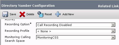
Step 22: Click Save.
Note: When configuring the monitoring party's phone (the Supervisor), ensure that the "MonitoringPart" partition is in the Calling Search Space used by the Supervisor's phone
Complete these steps to configure Call Recording:
Step 23 Select Call Routing Class of Control Partition.
Step 24: Click Add New.
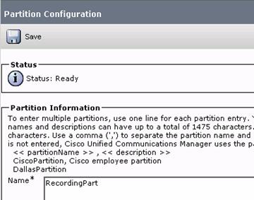
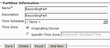
Step 25: Call the new partition "RecordingPart"
Step 26: Click Save
Once created, viewing the new partition will yield the screen below.
Step 27: Select from the main menu Call Routing Class of Control Calling Search Space.
Step 28: Click Add New.
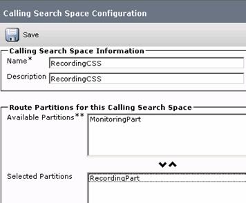
Step 29: Call the new Calling Search Space "RecordingCSS"
Step 30: Add the RecordingPart to the RecordingCSS.
![]()

Create a new Recording Profile
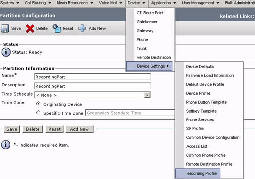
Step 31: Select Device Device Settings Recording Profile from the main menus
Step 32: Click Add New
Step 33: Give the Profile the name "RecordingProfile"
Step 34: Select the RecordingCSS as the Recording Calling Search Space.
Step 35: Assign as the Recording Destination Address extension 5001

Step 36: Click Save.
Create a SIP Trunk to the recording device with the IP address of the recorder.
Step 37: Select Device Trunk from the main menu.
Step 38: Click Add New
Step 39: Select SIP Trunk (the protocol information will be auto filled).
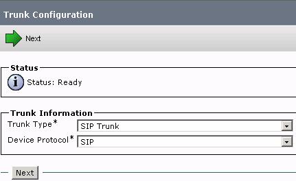
Step 40: Click Next.
Step 41: Give the SIP Trunk a name such as "RecordingTrunk"
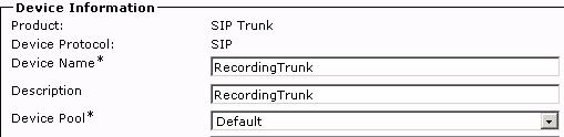
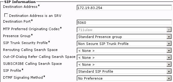
Step 42: Set the IP Address of the SIP Trunk as 172.19.83.254. (Scroll down to SIP Information) - Typically, the instructions provided by the recording device vendor would be used to configure specific settings for the SIP trunk.
![]()
![]()
![]()
Step 43: Click Save.
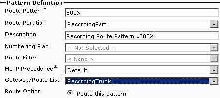
Create a new Route Pattern (500X) in the "RecordingPart" partition to link the recording destination addresses (DNs) of the recording device to the SIP trunk. Assign the SIP trunk created for this route pattern.
Step 44: Select Call Routing
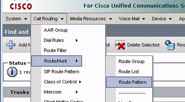
Step 45: Click Add New.
Step 46: Define the Route Pattern as follows:
Route Pattern - 500X
Route Partion - RecordingPart
Gateway/Route List - RecordingTrunk
![]()
![]()
![]()
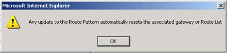
Step 47: Click Save.
Step 48: Click OK
Step 49: Click OK
Enable the 7971 phone (x1005) for recording
Step 50: Select Device Phone from the main menu
Step 51: Click Find or search the devices on Directory Number for x1005
Step 52: Select the phone
Step 53: Enable the Built-In-Bridge if it is not already on.

Step 54: Click Save (if BIB was not enabled.)
Step 55: Select Line 1 (x1005)
Step 56: Scroll down to Line 1 on Device SEP111213141516.
This is where the Recording and Monitoring is configured on this device.
Step 57: Select the Recording Profile created previously.
Step 58: Choose a desired recording option: Automatic Recording, Application Invoked (selective) or Disabled (default). For this exercise select Automatic Call Recording Enabled.

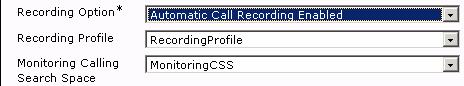
Step 59: Click Save.
Step 60: Reset the phone as required.
Intercom allows a user to place a call to a predefined target. The called destination auto-answers the call in speakerphone mode with mute activated. This sets up a one-way voice path between the initiator and the destination so that the initiator can deliver a short message.
Intercom is supported in CUCM 6.0 and on Cisco Unified IP Phones running firmware 8.3(1) or later.
Intercom Support for Cisco Unified IP Phones:
|
Cisco Unified IP Phone Model |
SIP |
SCCP |
|
7931 |
No |
Yes |
|
7941, 7961, 7970, 7971 |
Yes |
Yes |
|
7911, 7906, 7940, 7960 |
No |
No |
Create an
Step 1: Select
Call Routing
Step 2: Click Add New
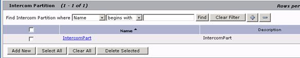
Step 3: Configure a new partition called "IntercomPart.".
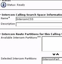
An Intercom Calling Search Space can be created (it is optional) to better control the reach ability of intercom lines. For the purpose of this lab the IntercomCSS Calling Search Space will be created.
Step 4 Select Call Routing Intercom Intercom Calling Search Space.
Step 5: Click Add New.
Step 6: Create an "IntercomCSS."
Step 7: Select the partition created in the previous step. A second Call Search Space called "IntercomPar_GEN" is automatically created as part of this process. To view this from the Related Links 'Go' back to Find/List. It will appear in the list of available Intercom Partitions.
Create the Intercom Directory Numbers
Step 8: Select Call Routing Intercom Intercom Directory Number.
Step 9: Click Add New
![]()
![]()
![]()
![]()
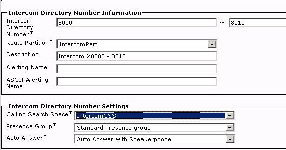
Step 10: Configure the Intercom Directory Numbers to range from x8000 to x8010
Step 11: Select the "IntercomPart" as the Route Partition
Step 12: Select the "IntercomCSS" as the Calling Search Space. (Optionally if the Intercom Calling Search Space in the previous step was not created, use the "IntercomPart_GEN" for the CSS.)
Step 13: Click Save.
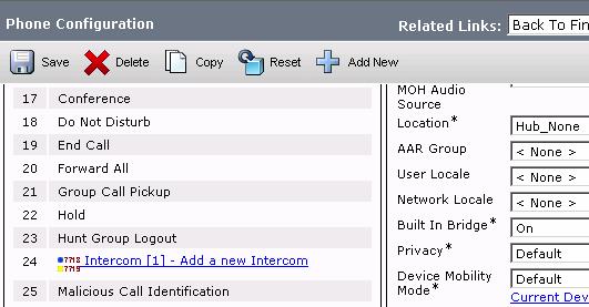
Now assign an intercom directory number on the 7971 phone (x1005)
Step 14: From the Phone configuration page select Intercom [1] - Add a new Intercom.
![]()
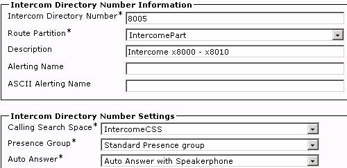
Step 15: Add intercom number 8005 to the device. The remaining information is auto filled using the settings created while configuring the Intercom Directory Number range.
![]()
Several enhancements to the ad-hoc conferencing feature provide the following advanced capabilities: A conference participant other than the conference controller can now add or remove conference participants. These advanced capabilities can be enabled or disabled by setting the value of two new service parameters.
Note: This feature currently works only from SCCP-based IP Communicator.
Complete these steps to allow all conference participants to add or remove conference participants:
Step 1: Select from the main menu System Service Parameters
Step 2: Select 172.19.83.1
Step 3: Select Cisco CallManager (Active)
Step 4: Change the "Advanced Ad Hoc Conference Enabled" service parameter to "True (Clusterwide Parameters (Features General))

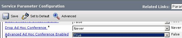
Step 5: Click Save
Step 6: From Workstation 1 setup a three party conference call that includes Workstation 2 and Workstation 3's phones.
Step 7: From Workstation 3's IP Communicator press the Conflist softkey button. The three parties on the conference call should appear.
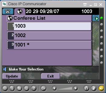
Step 8: From Workstation 3, add the hard phone to the conference.
Note: Remember the Workstation 1 IPC was the original conference controller.
![]()
Step 9: Select a party to remove from the conference. It should be possible to remove conference participants from the conference using both the original conference controller (Workstation 1 IPC) and another conference participant's phone (Workstation 3 IPC.)
Directed
Step 1: Create a new Partition called "IntPhonesPart" using the steps described earlier for Partition creation
Step 2: Create a new Calling Search Space called "PhoneCSS" using the steps described earlier for Calling Search Space creation. Add the IntPhonesPart Partition to the Calling Search Space.
Create two Directed Call Park Number/Ranges:
Step 3:
Select Call Routing Directed
Step 4: Click Add New
Step 5: Make one with a range of numbers 700[0-9] and allow these to revert to the original parker; assign a retrieval prefix of 99
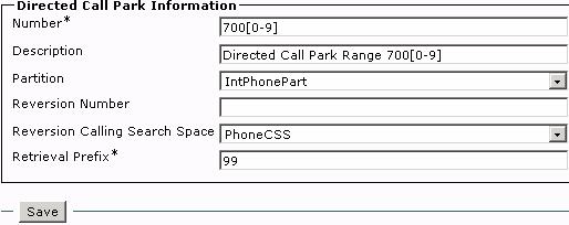
Step 6: Click Save
Step 7: Click Add New
Step 8: Make another Directed Call Park Number of 7101 and set the revert number to the system's hunt group pilot (x2000); assign this range a retrieval prefix of 98.
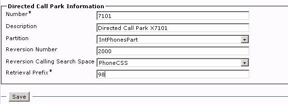
Step 9: Click Save.
Step 10: Set the Call Park Reversion Timer service parameter to 30 seconds. (System Service Parameters)
Step 11: Click Save.
Step 12: Assign the hard
phone, the


Step 13: Click Save.
Step 14: Close the BLF Directed Call Park Configuration window.
Step 1: Select Call Routing Class of Control Partition.
Step 2: Select Add New
Step 3: Type internal <Enter>
Step 4: Type mwi <Enter>
Step 5: Click Save
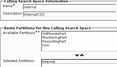
Step 1: Select Call Routing Class of Control Calling Search Space
Step 2: Click Add new
Step 3: Type internal in Name field
Step 4: Select internal from Available Partitions and then click the down arrow to move the selected partition
Step 5: Click Save
Repeat to create a voicemail Calling Search Space.
Step 6: Click Add New
Step 7: Type voicemail in Name field
Step 8: Select mwi from Available Partitions and then click the down arrow to move the selected partition
Step 9: Click Save
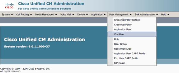
Step 1: Select User Management End User
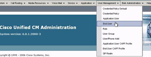
Step 2: Select Add New User
Step 3: Create a new user with the following parameters:
UserID - softphone1
Password - cisco
PIN - 12345
Last name - Fender
First name - Leo
Telephone Number - extension of Workstation 1 IPC
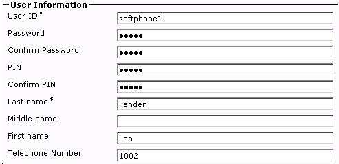
Step 4: Click Save
Step 5: Click on Device Associations


Step 6: Click Find
Step 7: Select the phone with Directory Number for Workstation 1's IPC. (The list of phones displayed may not be exactly as shown.)
![]()
![]()
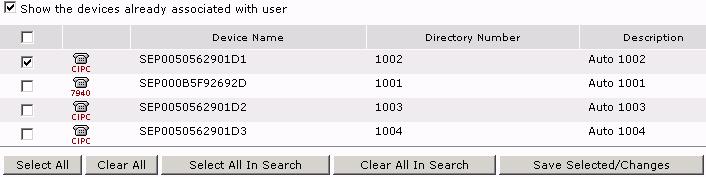
Step 8: Click Save Selected/Changes
Step 9: From Related Links click Go to return Back to User
Step 10: Select Add New User
Step 11: Create a new user with the following parameters:
User ID - softphone2
Password - cisco
Pin - 12345
Last name - Paul
First name - Les
Telephone Number - extension of Workstation 2 IPC
Step 12: Click Save
Step 13: Click on Device Associations
Step 14: Click Find
Step 15: Select the phone with the Directory Number for Workstation 2's IPC.
Step 16: Click Save Selected/Changes
Step 17: From Related Links click Go to return Back to User
Step 18: Select Add New User
Step 19: Create a new user with the following parameters
User ID - 7960phone
Password - cisco
Pin - 12345
Last name - Smith
Middle name - Reed
First name - Paul
Telephone Number - extension of the 7960 IP Phone
Step 20: Click Save
Step 21: Click on Device Associations
Step 22: Click Find
Step 23: Select the phone with Directory Number of the 7960 IP Phone.
Step 24: Click Save Selected/Changes
Step 1:
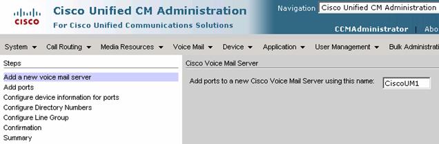
Step 2: Select Next (at the bottom of the screen)

Step 3: Select 2 from the Number of Ports drop down Menu

Step 4: Click Next
Step 5: In Description field, type Unity Connection
Step 6: Under Device Pool, Select Default
Step 7: Under Calling Search Space, Select voicemail
Step 8: Under Device Security
Mode, Select Non-Secure
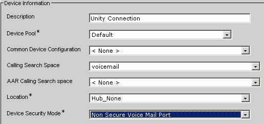
Step 9: Click Next
Step 10: In the Beginning Directory Number field, type 4001
Step 11: In the Partition drop down Menu, Select internal
Step 12: In the Calling Search Space drop down Menu, Select voicemail
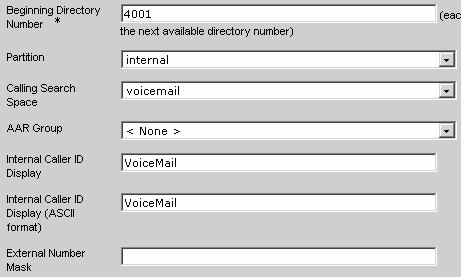
Step 13: Click Next.
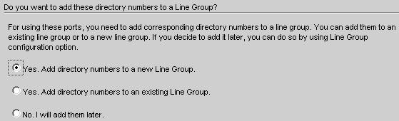
Step 14: Choose Yes, Add directory numbers to a new Line group.
Step 15: Click Next.
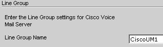
Step 15: Accept Default Line Group name
Step 16: Click Next
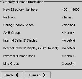
Step 17: Review all of the entries
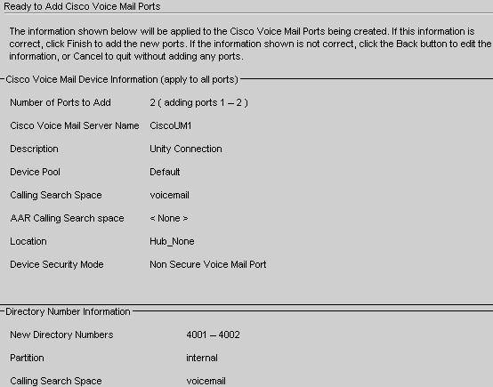
Step 18: Click Finish (scroll down)
The
following output shows the result of the
Step 1: Select 'Add this Line group to a new or existing Hunt List'.
![]()

Step 2: Click Add New
Step 3: In Name field, type vmail
Step 4: Select Default for UCM Group
Step 5: Select Enable this Hunt List
Step 6: Select For Voice Mail Usage
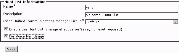
Step 6: Click Save
Step 7: Additional options will now appear at the bottom of the Screen.

Step 8: Select Add Line Group
Step 9: Select the line group created

Step 10: Click Save
Step 11: Click OK

Step 12: Click Reset
Step 13: Click Reset again
Step 14: Click Close
Step 15: Select Call Routing Route/Hunt Hunt Pilot from the main menus.
Step 16: Select Add New

Step 17: Type 4000 in the Hunt Pilot Field
Step 18: Type Voicemail Pilot in the Description Field
Step 19: From the Hunt List drop down Menu, select vmail
Step 20: Remove the checkmark from the Provide Outside Dial Tone box
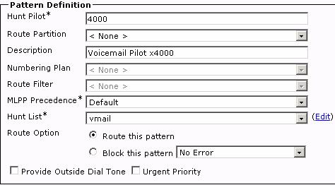
Step 21: Click Save
Step 1: Select Voicemail Message Waiting from the main menus
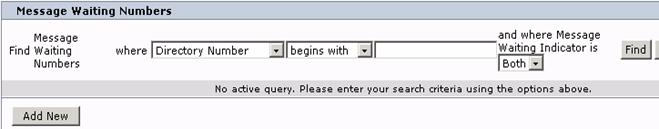
Step 2: Select Add New
Step 3: In the message Waiting Number field, Type 4998
Step 4: In the Partition Field, select mwi
Step 5: In the Message Waiting Indicator Field, select On
Step 6: In the Calling search Space Field, select voicemail
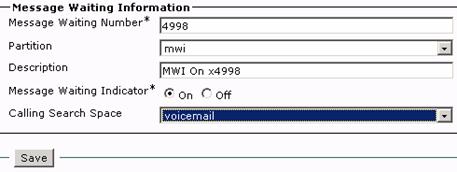
Step 7: Click Save
Step 8: Click Copy
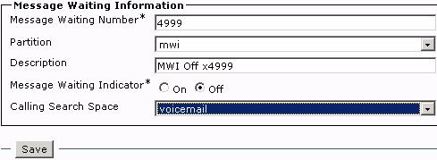
Step 9: In the Message Waiting Number Field, type 4999
Step 10: In the Message Waiting Indicator Field, select Off
Step 11: Click Save
Step 1: Select Voice Mail Voice Mail Pilot from the main menus.
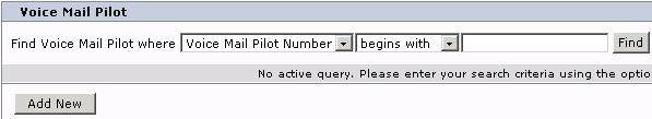
Step 2: Select Add New
Step 3: In the Voice Mail Pilot Number Field, Type 4000
Step 4: In the Calling Search Space field, select voicemail
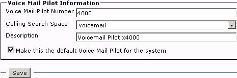
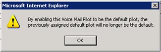
Step 5: Place a checkmark in the "Make this the Default Voice Mail Pilot for the System" box. If this message pops up, click OK.
Step 6: Click Save
Step 1: Select Voice Mail Voice Mail Profile from the main menus.
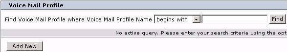
Step 2: Select Add New
Step 3: In the Voice Mail Profile name field, type Unity_Connection
Step 4: In the Voice Mail Pilot drop down Menu, Select 4000/voicemail.
Step 5: Place a checkmark in the "Make this the Default Voice Mail Profile for the System" box. If this box pops up, click OK.

Step 6: Click Save
Tasks 24 through 26 show the configuration of Unity Connection within the CUCMBE environment.
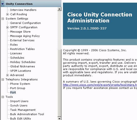
Step 1: From Main Navigation drop down menu, select Cisco Unity Connection Administration
Step 2: Select Go
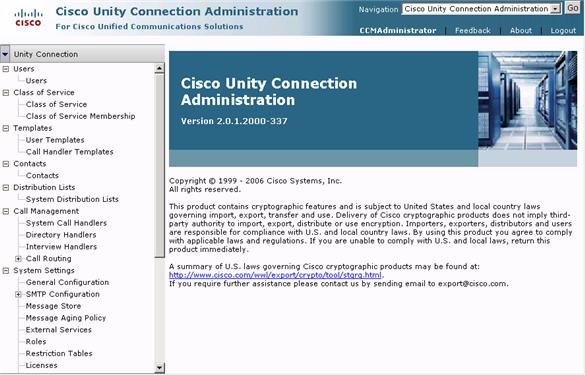
Step 3: From Main Menu at left, Scroll down and select System Settings Licenses
![]()
Step 4: Ensure the License file is installed. If not then select the check box and click on Install Selected.
Step 5: Once installed or if it is already installed, click on the CUCdemo.lic file.
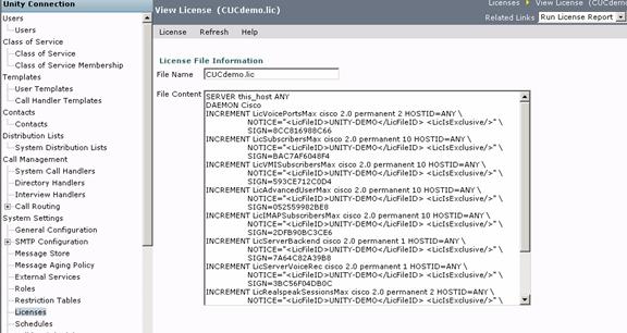
Step 6: Verify the number of Users, VM ports and other features that are available. (See example below.)
![]()

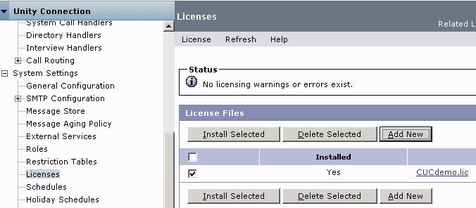
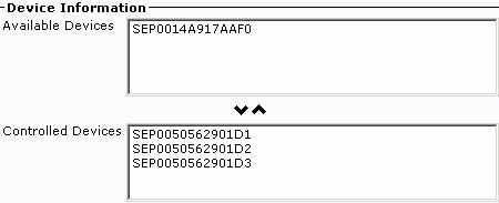
Step 1: From Main Menu at left, Scroll down and select Telephony Integrations/Port Group
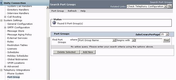
Step 2: Select Add New
![]()
![]()
![]()
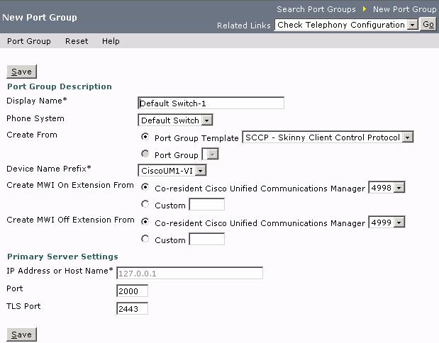
Step 3: The Device Name Prefix and MWI numbers that were previously configured are shown
Step 4: Under Primary Server settings, verify that the correct IP address of the server is listed
Step 5: Click Save.
Step 6: From Main Menu at left, Scroll down and select Telephony Integrations/Port
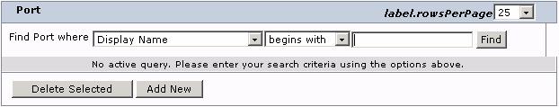
Step 7: Select Add New
![]()

Step 7: Type 2 in the Number of Ports field
Step 8: Select Save
Step 1: From the Top right Main Navigation menu, select Unity Connection Serviceability
Step 2: Select Go

Step 3:
Step 4: Under Unity Connection Services, Select Connection Conversation Manager
![]()

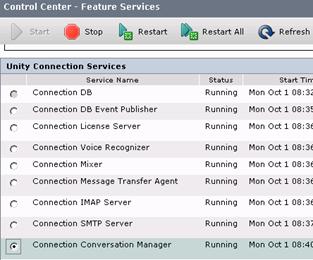
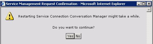
Step 5: Click Restart
Step 6: Click Yes
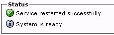
Step 7: Verify that the restart was successful and that the service is running
Step 8: From any of the Workstation IPC's call the voicemail pilot number created earlier. Unity Connection's opening greeting should answer.
Step 1: From the Top Right Navigation Menu, Select Cisco Unified CM Administration

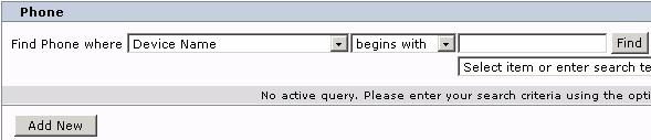
Step 2: Select Device Phone
Step 3: Click Find
Step 3: Select Workstation 1's IPC phone.
Step 4: Under Device Information Calling Search Space select internal.
![]()
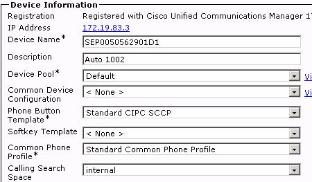
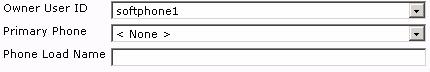
Step 5: Scroll down further under Device Information Owner User ID select softphone1.
Step 6: Click Save
Step 7: Click OK to the message that the phone needs to be reset.
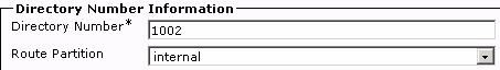
Step 8: On the left side under Association Information, click on the extension associated with this device.
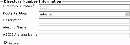
Step 9: Under Directory Number Information Route Partition, select internal.
![]()
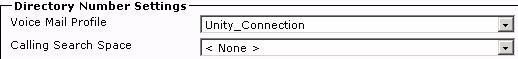
Step 10: Under Directory Number Settings Voice Mail Profile, select Unity_Connection.
![]()
Step 11: Under Call Forward and Call Pickup Settings Voice Mail, place a check box next to:
Forward Busy Internal and External
Forward No Answer Internal and External
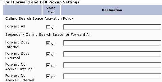
Step 12: In the Display and the Line Text fields, Type: Leo Fender
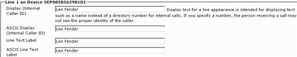
Step 13: Click Save.
Step 14: Scroll to the bottom of the screen and under User Associated with Line, click Associate End Users.
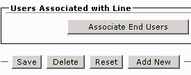
Step 15: Select Find
Step 16: Select softphone1 (Leo Fender's username.)
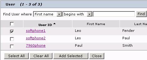
Step 17: Click Add Selected
Step 18: Click Save
Step 19: Select Reset/Restart
Step 20: Scroll down to User Associated with Line and click on Fender,Leo
Step 21: In the End User Configuration scroll down to Directory Number Associations and select the Primary Extension for Leo Fender.
![]()
Step 22: Click Save
Step 23: Repeat Steps 2 through 22, substituting the extension for Workstation 2's IPC and softphone2 (Les Paul) for the user ID
Step 1: Select Unity Connection Administration from the Main Navigation Menu
Step 2: Click Go
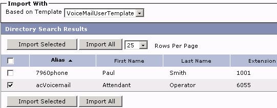
Step 3: From the menu selections on the left side of the screen, select Tools Import Users

Step 4: Select Find
Step 5: Place a checkmark next to softphone1 (Leo Fender) and softphone2 (Les Paul).


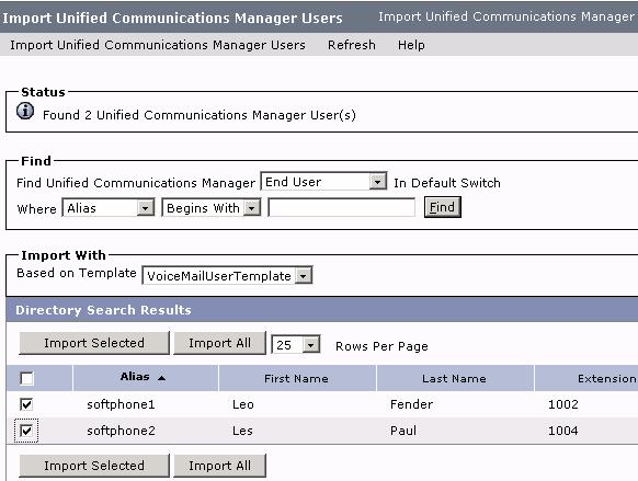
Step 6: Select Import Selected
Step 7: Verify that the users were imported by the message displayed at the top of the Import window
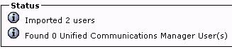
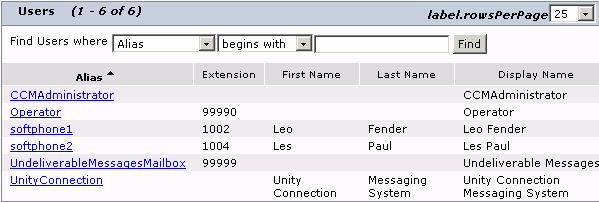
Or by selecting Users from the Users menu on the left side of the screen. Users softphone1 and softphone2 should be listed.
Step 1: Return to the Main LabOps Lab Topology page and connect to Workstation 2
Step 2: If it is not already running, launch Cisco IP Communicator.
Step 3: Verify that the IP Communicator has an extension number assigned by CUCM.
Step 4: Click the Messages button or dial extension 4000. Unity Connection should answer with the initial login greeting requesting that the voicemail account be personalized.
Step 5: Hang up.
Step 6: Return to the Main LabOps Lab Topology page and connect to Workstation 3.
Step 7: If it is not already running, launch Cisco IP Communicator.
Step 8: Verify that the IP Communicator has an extension number assigned by CUCM.
Step 9: Place calls and leave messages from one IP Communicator to the other. Login and retrieve messages to and verify that Unity Connection is correctly configured.
Step 1: ![]() In
the credential policy for the Phone View CTI user, verify that the User Must
Change at Next Login and the Does Not Expire check boxes are both unchecked.
Otherwise, Phone View will not work. From the main Cisco Unified CM Administration Page select User
Management Credential Policy Default.
In
the credential policy for the Phone View CTI user, verify that the User Must
Change at Next Login and the Does Not Expire check boxes are both unchecked.
Otherwise, Phone View will not work. From the main Cisco Unified CM Administration Page select User
Management Credential Policy Default.
Step 2: Select the Default Credential Policy for the Application User
Step 3: Uncheck the User Must Change at Next Login check box.
Step 4: Click Save.

Step 5: ![]() Select
User Management Application User from the
main menu.
Select
User Management Application User from the
main menu.
Step 6: ![]() On
the Find and List Application Users page, click Add New.
On
the Find and List Application Users page, click Add New.

On the Application User Configuration page, do the following substeps to create a CTI user account that will have access to all user phones for Phone View:
Step 7: In the User ID field, enter "PhoneViewUser".
Step 8: In the password field, enter cisco.
Step 9: In the Confirm Password field, re-enter the password that was entered in Step 7.

Step 10: Associate the user phone devices with the new CTI user.
Step 11: Click Save.
To Enable Phone View for a Phone System (Cisco Unified Communications Manager/Business Edition)
Step 1: ![]() Navigate
to Cisco Unity Connection Administration
Navigate
to Cisco Unity Connection Administration
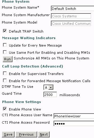
Step 2: Select from the Menus on the left Telephony Integrations Phone System.
Step 3: ![]() Select
Default Switch.
Select
Default Switch.
 .
.
Step 4: ![]() Under
Phone View Settings, check the Enable Phone View check box.
Under
Phone View Settings, check the Enable Phone View check box.
Step 5: ![]() Scroll
down to the CTI Phone Access User Name field, enter PhoneViewUser. Note that the
user name is case-sensitive.
Scroll
down to the CTI Phone Access User Name field, enter PhoneViewUser. Note that the
user name is case-sensitive.

Step 6: ![]() In
the CTI Phone Access Password field, enter the password for the user (cisco).
In
the CTI Phone Access Password field, enter the password for the user (cisco).
 Step 7:
 ![]() Click
Save.
Click
Save.
Step 1: Under User, select softphone1, go to Edit - Phone Menu
 Step 2: Enable 'Finding Messages with Message Locator'
 Step 3: Enable Phone View
Step 4: Click Save
Note: Phone View does not function with IPC as IPC does not use the IP Phone Services URL.
Step 1: Log into the voicemail account for the user on Workstation 1
Step 2: Press 5 to access Message Locator
Step 3: Press 5 to find all messages
Step 4: When the list of messages display on the IPC screen, use the following softkeys to learn how Phone View interacts with Unity Connection.
|
Key |
Action |
|
Select |
Start message playback from the selected message. |
|
Next |
Go to the next page of messages, if applicable. |
|
Previous |
Go to the previous page of messages, if applicable. |
|
More |
Displays the Goto and Exit soft keys. This key appears only on phones that display a maximum of 4 soft keys. |
|
Goto |
Skip to the message specified. Phone View displays a screen that allows you to specify the message number by using the phone keypad. When the number is entered, the message is highlighted. |
|
Exit |
Exit the Phone View display. This action returns you to the search criteria prompt. |
Step 5: As UC plays the message use the following keys to control playback as you listen to the message
|
Key(s) |
Action |
Key(s) |
Action |
|
Restart message |
Rewind message |
||
|
Save |
Pause/Resume |
||
|
Delete |
Fast-forward |
||
|
Slow playback |
Fast-forward to end |
||
|
Change volume |
Skip message, save as is |
||
|
Fast playback |
|
||
1. Not available on some systems
Step 6: The following keys can be used after the message is listened.
|
Key(s) |
Action |
Key(s) |
Action |
|
Replay message |
Forward message |
||
|
Save |
Save as new (The message waiting indicator on your phone may be triggered.) |
||
|
Delete |
Rewind message |
||
|
Reply |
Play message properties |
||
|
Reply to all |
Save as is |
||
|
Call the user |
|
||
1. Not available on some systems
Add an extension to Workstation 1
Step 1: Add DN
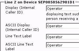
Step 2: Change the Display and Line Info for Line 2
Step 3: Change the call waiting settings to only accept one call at this extension.
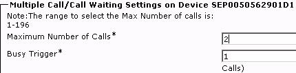
Step 4: Click Save
Step 5: Repeat for a 2nd extension on Workstation 2's IPC setting the DN as 6051
Step 6: Create a new DN. Call Routing Directory Number. Give it the number 6055 and assign it to the internal route partition.
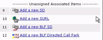
Step 7: On Workstation 1's IPC phone setting click on the Modify Button Items button under Association Information.
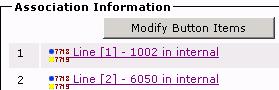
Step 8: Click OK

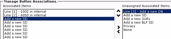
Step 9: Select the top Add a New SD from the left pane and move it to the right pane using the arrow buttons between the two panes.
![]()
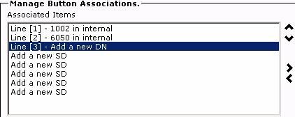
Step 10: Select Line [3] - Add a new DN from the right pane and move it to the left pane and move it to under Line [2] - 6050 in internal
![]()
Step 11: Click Save
Step 12: Click Close.
Step 13: Add the DN 6055 created earlier to Line [3] just added.
Step 14: Reset the phone.
Step 15: Select User Management End User
Step 16: Click Add New
Step 17: Create the following user where the voicemail will be deposited from the Attendant Console.
Username: acVoicemail
Password: cisco
PIN: 12345
Last name: Operator
First name: Attendant
Telephone Number 6055
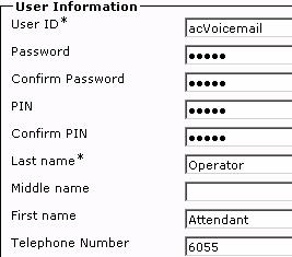
Step 18: Click Save
Step 19: Click on Device Associations
Step 20: Select the device with extension 6055
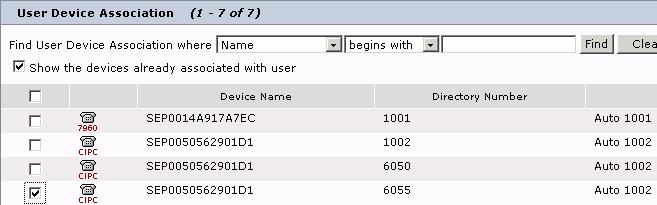
Step 21: Click on Save Selected/Changes and go back to the User page
Step 22: Scroll down and select 6055 as the Primary Extension for this Directory Number Association.
![]()
Step 23: Click Save
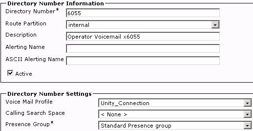
Step 24: Return to Device Phone
Step 25: Select Workstation 1's IPC
Step 26: Click on Line [3]
Step 27: Update the Route Partition to internal
Step 28: Select the Unity_Connection Voice Mail Profile
Step 29: Select Forward All under the Call Forward and Call Pickup Settings

Step 30: Click Save
Step 31: Scroll down and click on Associate End User under User Associated with Line
Step 32: Select the acVoicemail userID
Step 33: Click Add Selected
Step 34: Scroll down and select the user just associated with this device.
Step 35: Click Save.
Now import the User into Unity Connection:
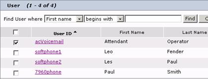
Step 36: Select Cisco Unity Connection Administration from the top right menu's and click Go.
Step 37: From the Tools menu on the left select Import Users
Step 38: Select the acVoicemail user
Step 39: Click Import Selected
Step 40: Ensure your user was successfully imported using the techniques learned earlier in the lab.
Step 41: Return to CUCM Administration
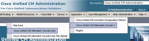
Step 1: Choose Application Cisco Unified CM Attendant Console Cisco Unified CM Attendant Console User.
Step 2: Add New
Step 3: Enter the appropriate configuration settings:
Username - acUser1
Password - C1sco123
Reconfirm password
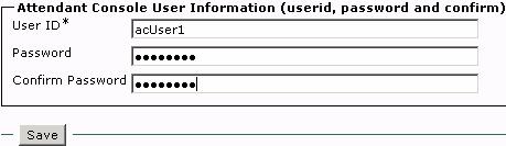
Step 4: Click Save.
Create a second AC User:
Step 5: Add New
Step 6: Enter the appropriate configuration settings:
Username - acUser2
Password - C1sco123
Reconfirm password
Step 6: Click Save.
Create the Application User
Step 2: Choose User Management > Application User.
Step 3: Click Add New.
Step 4: Enter the user ID ac.
Step 5: In the Password field, enter the password C1sco123.
Step 6: In the Confirm Password field, reenter the password.
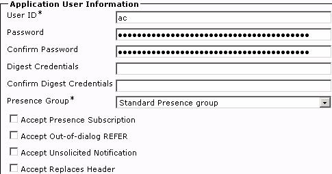
Step 8: Click Save.
Now create another Application (Device) User:
Step 9: Click Add New.
Step 10: Create the device authentication user, enter the user ID 'ACDeviceAuthenticationUser' in the User ID field.
Step 11: In the Password field, enter the password C1sco123.
Step 12: In the Confirm Password field, reenter password.
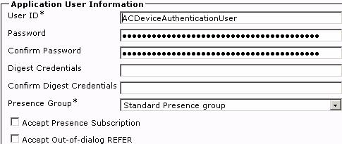
Step 14: Click Save.
You can enable Cisco Unified Communications Manager Attendant Console devices without associating each of them with the Cisco Unified Communications Manager Attendant Console application user by enabling the super provider feature. To do this, add the Cisco Unified Communications Manager Attendant Console application user to the Standard CTI Allow Control of All Devices user group.
Step 1: Select Back to Find/List from Related Links and click Go.
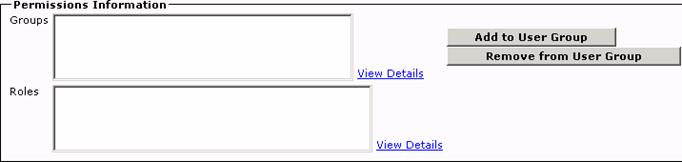
Step 2: Select the ac user.
Step 3: Scroll down to Permissions Information and click on Add to User Group.
Step 4: Scroll down and select the Standard CTI Allow Control of All Devices,
Standard CTI Enabled and
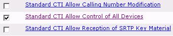
Step 5: Click on Add Selected.

Step 6: Click on Save.
After you enable the super provider feature, you do not have to associate pilot points and attendant phones to the Cisco Unified Communications Manager Attendant Console user.
During an upgrade from Cisco Unified Communications Manager Release 4.x, the system automatically converts the attendant console application user to a superprovider user and disassociates the devices that were previously associated to the application user.
Configure a DN for the Pilot Point
Step 1: Select from the main menu Call Routing Directory Number
Step 2: Click Add New
Step 3: Enter in 6000 as the DN
Step 4: Select the internal Route Partition
Step 5: Click Save
Create the Pilot Point
Step 6: Choose Application Cisco Unified CM Attendant Console Pilot Point.
Step 7: Click Add New.
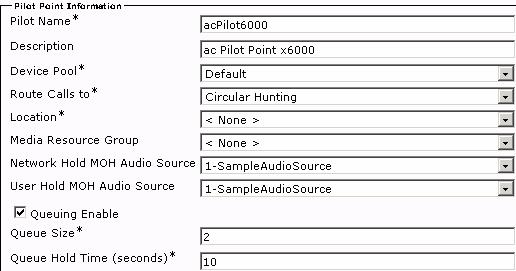
Step 8: Enter the following settings:
Pilot Name: acPilot6000
Description: acPilot Point x6000
Device Pool: Default
Route Calls To: Circular Hunting
Location: Hub_None
Network Hold MOH Audio Source: Select the Sample Audio available
User Hold MOH Audio Source: Select the Sample Audio available.
Queuing Enable: Yes
Queue Size: 2
Queue Hold Time (in seconds): 10
Step 9: Click Save.
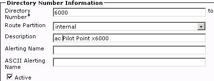
Step 10: To associate the directory number created above for the pilot point, click Line 1 in the Association Information pane.
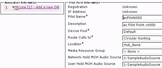
Step 11: Enter the directory number 6000 and click tab. The remaining fields will auto fill with the previous configured settings for this DN.
Step 12: Click Save.
Task 39 - Associating Devices with the Attendant Console Authorization User
Before the attendant uses the attendant console, you must associate the attendant console phones to the attendant console device authorization user that you created on the Application User Configuration window. Perform the following procedure:
Step 1: Choose User Management Application User
Step 2: Perform a search for the device authorization user (ACDeviceAuthenticationUser) that you set up previously.
Step 3: From the Available Devices list in the Device Associations box, choose the Workstation 1 and 2's IPC's and the Pilot Point just created.
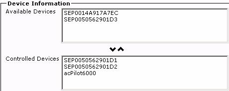
Step 4: Click Save.
Configure the pilot point for which you want to add hunt group members, including associating the directory number to the pilot point.
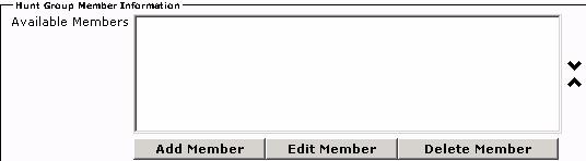
Step 1: Return to the Attendant Console pilot point created above. Application Cisco Unified CM Attendant Console Pilot Point.
Step 2: Click Add Member in the Hunt Group Member Information area.
Step 3: Select User Member as the Member Option
Step 4: Under User Member Information, select User Name acUser1 and Line Number 2
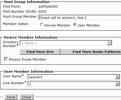
Step 5: Click Save.
Step 6: Repeat steps 3 through 5 selecting User Name acUser2 and Line Number 2.
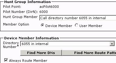
Step 7: Click Add Member.
Step 8: Select Device Member as the Member Option.
Step 9: Under Device Member Information if extension 6055 in internal is not in the drop down list then click on Find More DNs.
Step 10: Select the extension 6055 in Partition internal.
Step 11: Click Add Selected.
Step 12: Click the Always Route Member checkbox.
![]()
Step 13: Click Save
Step 14: Click Close
Step 15: Ensure the Member Information is arranged in the following order:

Step 16: Click Save
Note: Cisco strongly recommends that the last hunt group does not link back to the first hunt group.
Perform the following steps to update Cisco CallManager Attendant Console Server service parameters.
Start the CM Attendant Console Server service:
Step 1: Select the Cisco Unified Serviceability option from the top right hand drop down list
Step 2: Click Go.
Step 3: Select Tools Service Activation
Step 4: Under CTI Services click the Cisco CallManager Attendant Console Server
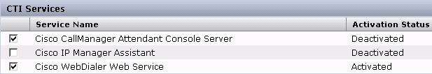
Step 5: Click Save
Step 1: On Workstation1, create the following corporate directory file, using Notepad. Call it CorporateDirectory.txt:
Les,Paul,1003,Engineering
Fender,Leo,1002,Sales
Smith,Paul,1004,Marketing
Smith,Brian,1005,Customer Support
Smith,,,Marketing
Step 2: In Cisco Unified Communications Manager Administration, choose Application Cisco Unified CM Attendant Console Cisco Unified CM Attendant Console User File Upload.
Step 3: Choose Upload File.
Step 4: Browse to the CorporateDirectory.txt file and click Upload.
Step 5: Click Close.
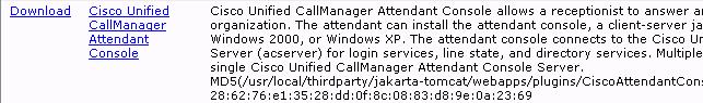
Step 1: Choose Application Plugins.
Step 2: Click Download next to Cisco Unified Communications Manager Attendant Console to download the application. Save it to the desktop. Alternatively select to Run the install at this time.
Step 3: Find the Attendant Console file just downloaded and double click to install
Step 4: To acknowledge the installation, click Yes.
Step 5: In the initial installation wizard window, click Next.
Step 6: Accept the agreement and click Next
Step 7: Accept the default location, click Next
Step 8: In the Ready to Install window, click Next.
Step 9: Click Finish.
Step 1: On Workstation1, if the attendant console icon is on the desktop double click to open the application. Alternatively select Start Programs Cisco Unified Communications Manager Cisco
Step 2: Click Yes to launch the attendant console.
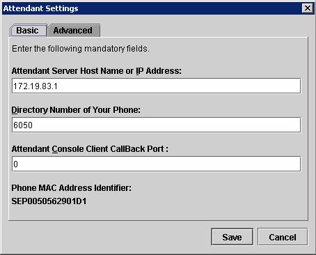
Step 3: Enter the following configuration settings in the Attendant Settings window on Workstation 1.
Attendant Server Host Name or IP Address: 172.19.83.1
Directory Number of Your Phone: 6050 (6051 on Workstation 2)
Step 4: Click Save.
Step 5: Click Save.
Note: DO NOT log into the Attendant Console application on either Workstation. Once the application is installed on Workstation 2 proceed to Task 46.
Ensure the Pilot Point registers with CUCMBE.
Step 1: Log in to the Attendant Console application as acUser2 on Workstation 2
Step 2: Dial 6000 from Workstation 3's IPC. Does the call go to acUser2? DO NOT HANG UP.
Step 3: Dial 6000 from Workstation 1's IPC. Does the call go into the queue?
Step 4: Hang up the call on Workstation 3. Does the call in the queue go to acUser2?
Step 5: Log in to the Attendant Console Application as acUser1 on Workstation 1.
Step 6: Dial 6000 from Workstation 3's IPC. Who gets the call? Why? Is this the expected behavior?
Step 7: Transfer the call (blind) to the extension on the 7960. Did the call get connected?
Step 8: Hang up the call on Workstation 3.
Step 9: Log out your Attendant Console agents and close the application.
Step 1: Change the queue from Circular Hunting to Broadcast Queue. See Task 38 Step 8.
Step 2: Add two more extensions to Workstation 3 (ext 1006 and 1007 in internal).
Step 3: Reset the IPC.
Step 4: Log in to the Attendant Console Application as acUser1 on Workstation 1
Step 5: Log in to the Attendant Console Application as acUser2 on Workstation 2
Step 6: Dial extension 6000 from Workstation 3 line 1. Which agent did the call go to? Was this the expected behaviour? DO NOT HANG UP.
Step 7: Dial extension 6000 from Workstation 3 line 2. Which agent did the call go to? Was this the expected behavior? DO NOT HANG UP.
Call goes to Broadcast queue:
Step 8: Dial extension 6000 from Workstation 3 line 3. Which agent did the call go to? Was this the expected behaviour? Did the call get queued?
Step 9: Hang up the call with acUser1. Did the agent get the next call automatically? Did the agent have to pick up the call from the Broadcast queue? DO NOT HANG UP.
Step 10: From the available line on Workstation 3, dial extension 6000. Did the call get queued?
Call goes to voicemail:
Step 11: From an available line on Workstation 3, dial extension 6000. Did the call get queued? What happened? Was this the expected behaviour?
Step 1: Navigate to Worstation1 and double click the RTMT Icon
Step 2: Enter Host IP Address = 172.19.83.1
Step 3: UserID and password = CCMAdministrator/C1sco123
Step 4: Leave the port at 8443 and the Secure Connection box checked.
Step 5: RTMT version 6.0 will open. If verification of the Digital Certificate is required, click Yes.
Step 6: The application will request that you select a configuration. Select Default then click OK.
 Task 47 -
Viewing the System Summary
Task 47 -
Viewing the System Summary Step 1: The opening System Summary view shows server information. Review settings under the System pane on the top left.
Note: There are Communications Manager and Unity Connection panes as well on the lower left.
Note: Alert history list on the main System Summary page, including failed authentication attempts, are against CUCM-BE.
Step 1: View Server statistics by clicking on the views under the Server section - CPU and Memory, Process, Disk Usage, Critical Services
Step 2: Click on 'Critical Services' in left pane. The local host at the top of the page under 'Critical Services at Host' will default to the CUCM-BE (172.19.83.1). Notice the three tabs available - System, Communications Manager and Unity Connection. All the critical services can be viewed from this interface.
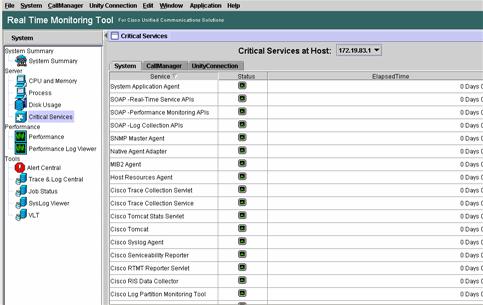
Step 3: Click on the UnityConnection tab. All services should show a service status of up. See the bottom of the page for the legend for icons.
![]()
Step 4: Click the Communications Manager tab. Some of the services are up and some are not activated.
Step 5: Look and see if the right services are activated or not.
Step
6: Highlight a service and right click on
it.

Step 1: Under Performance, click on the server IP address, under StandAloneCluster. There are several statistics and sub stat details that can be collected by double clicking on the options.
Step 2: Create up to six screens for performance details under the Call Manager tab shown on the bottom of the display.
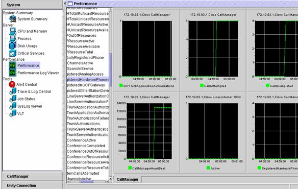
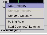
Step 3: Right click on the tab and select New Category, name it CUC and add six CUC performance stats to that window.
Step 4: Toggle between the performance screens that were created to see how the program works.
Step 1: Review the tools available in the system pane through RTMT. Notice how future traces, logs, and syslog events can be viewed from one interface.
Communications Manager and Unity Connection are one interface
Step 2: Click on the Call Manager pane on the bottom left of the page.
 Step 3: Evaluate the tabs of Communications Manager Summary, Call Activity,
Trunk Activity, Gateway Activity, Phone Summary, etc..
Step 3: Evaluate the tabs of Communications Manager Summary, Call Activity,
Trunk Activity, Gateway Activity, Phone Summary, etc..
Step 4: Click on the Unity Connection pane, located at the bottom left of the page.
There is only one selection to view - Port Monitor
Step 5: Select a port and click Start Polling, in a bit, click Stop Polling and look at results.
Note: These selections can all be done via the tool bar at the top by clicking on Application. RTMT will offer a quick link over to the system admin GUIs. Function keys are also available to jump over to the admin GUIs.
Unified Mobility (Single Number Reach) Overview
This module will cover the configuration of Mobile Connect sometimes referred to as Single Number Reach (SNR) which has been integrated with Communications Manager 6.x. By the end of this module a Remote Destination profile will be configured and enabled so that calls can be taken from either a cell phone or desk phone and moved between the two devices.
Enable
the Cisco Unified
Step 1: From the User Management drop down menu choose the End User Configuration page.
Step 2: Select the softphone1 user.
Step 3: Click the Mobility and Enable Mobile Voice Access check boxes. Make sure that the phone is associated to the user.
Step 4: Click Save.
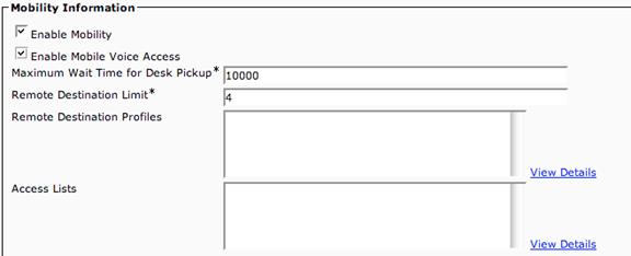
Step 5: Repeat this process for user softphone2.
Step 6: Go to System Licensing License Unit Report
Note: Checking the Enable Mobility checkbox increments the Units Used by 2.
![]()
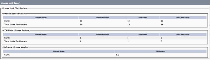
Before
![]()
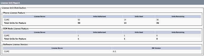
After
Create a Remote Destination Profile
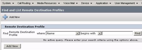
Step 7: Choose Device Device Settings Remote Destination Profile.
Step 8: Click Add New
Step 9: In the Remote Destination Profile Information configuration screen, enter the following:
Name: softphone1-rdp
Description: softphone1 remote destination profile
User ID: softphone1
Device Pool: Default
All other fields: Accept Defaults
Step 10: Click Save
Step 11: On the left hand side of the screen, under the Association Information Heading, click the Add a new DN link.

Step 12: In the Directory Number field enter 'x' (which is the 1st line appearance on the softphone1)
Step 13: Leave all other settings as they are.
Step 14: Click Save
Step 15: At the upper right hand corner of the screen, under related links Select Configure Device (softphone1-rdp) and click Go
Step 16: Under the Associated Remote Destinations click the Add a New Remote Destination link.

Step 17: Under the Remote Destination Information section enter the following:
Name: softphone1-cell
Destination Number: x (where x is 91 and the cell number of the phone used for this lab)
Remote Destination Profile: softphone1-rdp
Mobile Phone: Checked (this field tells UCM to ring this destination when Send call to Mobile Phone is selected.)
Enable
Step 18: Click Save.
(A warning about Mobility Softkey will appear. Please continue. This will be created later.)
 Step 19: After saving,
under the Association Information, Check the Line Association box to associate
Softphone1 DN with this mobile number.
Step 19: After saving,
under the Association Information, Check the Line Association box to associate
Softphone1 DN with this mobile number.
Step 20: Change the Delay Before Ringing Timer to 0.
Step 21: Click Save.
![]()

Step 22: From the Workstation 2 dial Workstation 1's DN. After several rings the number in the remote destination should start ringing.
Mobile Voice Access allows two-stage dialing or a remote user Direct Inward System Access (DISA) access. The Mobile Voice Access feature relies on the Cisco Unified Mobile Voice Access Service, which MUST be activated manually from the Unified CM Serviceability configuration page.
Step 1: Select System Service Parameters from the main menu. (On systems with multiple CUCM's this service can only be activated on the publisher node.)
Step 2: Select the CUCMBE
Step 3: Select Cisco CallManager service, then scroll down to the Clusterwide Parameters (System - Mobility) section
Step 4: Change the Enable
Step 5: Change the Enable
Step 6: In the Mobile Voice Access Number field enter 1551.
Step 7: The Matching Caller ID with Remote Destination needs to be change to Partial Match.
Step 8: Leave the Number of Digits for Caller ID Partial Match with the value of 10.
Step 9: Click Save
![]()
![]()
![]()
![]()
![]()

Step 10: Restart the CallManager Service from the
Step 11: In the upper right corner select Cisco Unified Serviceability and select Go.
Step 12:
Step 13: Select the Cisco CallManager radial button
Step 14: Click Restart
![]()

Step 15: After the CallManager service restarts ensure that the phones register again.
Step 16: Navigate back to CM Administration.
Step 17: Select Media Resources and Mobile Voice Access from the main menu.
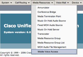
Step 18: Enter the Pilot number 1551
Step 19: Move the Mobile Voice Access Localization feature English United States down from the Available Locales to Selected Locales.

Step 20: Click Save
Step 21: Select Call Routing Mobility Configuration menu to setup a handoff (DID).
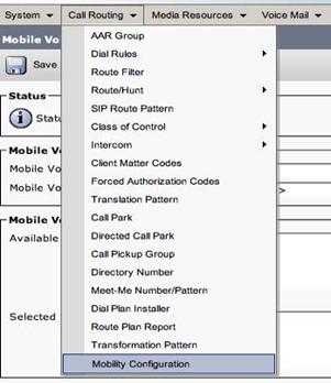
Step 22: Enter 1111 in the Handoff Number field
Step 23: In the Enterprise Feature Access field enter 1999
Step 24: Click Save
![]()
![]()
Step 25: Select Device Device Settings Softkey Template to configure the Mobility Softkeys.
Step 26: Click on Find
Step 27: Click Standard User
Step 28: Select Copy
Step 29: Name it Standard User - Mobility
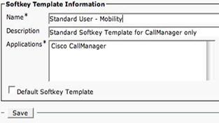
Step 30: Click Save
Step 31: From Related Links return to Configure Softkey Layout by clicking Go
Step 32: Select the On Hook call state Move Mobility over to the right
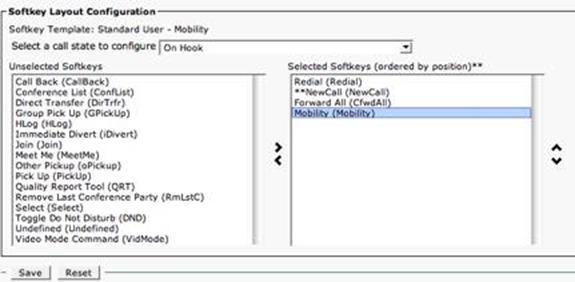
Step 33: Click Save
Step 34: Select the Connected call state
Step 35: Move Mobility (Mobility) over to the right

Step 36: Click Save
Step 37: Return to the Phone configuration page for Workstation 1's IPC.
Step 38: Associate the Softkey Template on the phone configuration page with the Softkey template that was just created.

![]()

Step 39: Click Save
Step 40: Reset/Restart the phone.
It is now possible to call in from a cell phone or the device that was created as the remote destination.
Step 1: Create a H323 gate by going in CCM Administration to Device Gateway Add a new gateway
Step 2: Choose from the list of gateways, H323 gateway
Step 3: Name it 172.16.1.1 and give it the description of Mobility Gateway.
Step 4: Use the default Device Pool
Step 5: Use 172.16.1.1 as the IP address for the gateway
Step 6: Click on Save
Step 1: Create a route pattern to route calls to the mobility gateway by going to Call Routing > Route/Hunt > Route Pattern
Step 2: Use 9.1[2-9]xx[2-9]xxxxxx as the pattern.
Step 3: Select the Mobility Gateway from the drop down list
Step 4: On Called Party, choose to do a Pre-dot discard.
Step 5: Click on Save
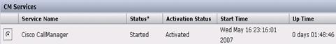
Step 1: Browse to Call Manager Serviceability.
Step 2: Click on Trace Trace Configuration
Step 3: Choose your server
Step 4: Choose the CM Services
Step 5: Cisco Call Manager
Step 6: Check the box to turn off tracing and click save. This will create a new file to start the tracing.
Step 7: Uncheck the box to turn tracing back on. This creates a new file to store the trace information in.
Step 8: Change the tracing level from Error to Detailed
Step 9: Check all boxes for trace parameters. Do not select devices to do a trace, you will miss key information in call-processing.
Step 10: Click on Save
Step 1: Make a call to the phone that was configured in the mobility exercise from another IPC phone.
Note: The calls will result in a fast busy signal because this gateway does not exist.
Step 1: Double-click Remote Browse (Located within RTMT under Trace Log Central Options).
Step 2: Choose the appropriate radio button, and click Next.
Step 3: Choose Trace Files
Step 4: In the Select CCM Services/Applications tab, perform the following task:
Step 5: Click next
Step 6: Select the CUC Services/Application tab and check Select All Services on All Servers check box and click Next
Step 7: In the Select System/Application Tab, choose Select All Services on all Servers check box.
Step 8: Click Finish
Step 9: After Traces become available, a message displays, Click Close
Step 10: To display the results, navigate to the file through the tree hierarchy. After the log file name displays in the pane on the right side of the window, right-click the mouse to select the type of program with which to view the file or double click the file to display the file in the default viewer.
Step 11: After the viewer opens, click CTL-F and type in the number to populate as the remote destination number, most likely the cell phone.
Step 12: The number should be highlighted with a db Mobility tag in front of it. This is CallManager doing call processing with Mobility Connect.
Thank you for taking the time to complete this lab. We hope that this was a valuable exercise for you.

|
