WIND POWER Turbines
Research Paper
I what is a wind power turbine?
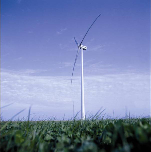
Here what a wind power turbine looks like:
The shape comes from studies which lead to a type that we found all around the world.
The number of blades doesn't change the capacity of a turbine; it is just a question of equilibrium and resistance. 3 blades is not more efficient than 2 it is just a question of forces repartition when the wind is too important ( the 2 blades turbine need more wind to supply an equivalent energy). We will see the different parts constituting a turbine and then we will take a look at the places to put them to maximize their efficiency.
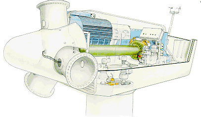
This is the top part of a turbine:
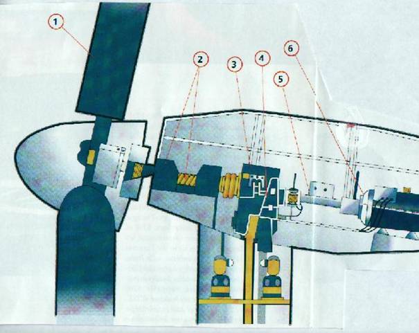
The blades (1) rotate and make the slow or primary shaft rotate (2). This shaft is to go in a gear box that uses the high couple and low speed of the rotation to change it in a higher speed one (3).In (5) it is the secondary shaft that has a higher rotational speed and that goes directly into the generator. In (4) we have an hydraulic system that allows the turbine around its axis to face the wind. This system is also used in emergency cases to stop the turbine. 21221m1219v
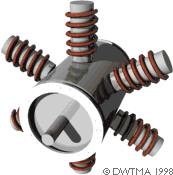
THE ROTOR HUB
The rotor blades capture the wind and transfer its power to the rotor hub. This part held the blades. This part can make the blades rotate on their own axis to change the attack angle and adapt it to the direction and force of wind. It is enclosed in a spinner which has no specific use but protects it and is more beautiful.
THE ROTOR AND THE BLADES
The most important part of the turbine. 21221m1219v Usually made with carbon or glass fibber for its resistance and elasticity their length vary up to 40 metres to maximize the power produced:
 the distance here is the diameter of the turbine. 21221m1219v
This scheme represents the size of the blades with respect to the power produced by the turbine. 21221m1219v The best efficiency for a turbine is obtained for a definite force of wind. I f the wind is stronger, the turbine has a system that controls the rotational speed of the blades for them not to break. They rotate around their own axis like a plane's wing to stall at a certain speed. This is called the Stall Effect. This possibility to rotate is used to maximize efficiency and to slow down the speed of the blades in extreme conditions. The maximum speed of the last end of a blade can go up to 216Km/H. Many tests, like static and dynamic test are done on the blades to see if they can undergo high pressure and torsion forces.
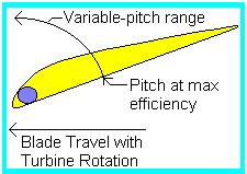 As shown
here, the position of the blade.
As shown
here, the position of the blade.
On this
picture we describe how the blade is attached to the rotor: 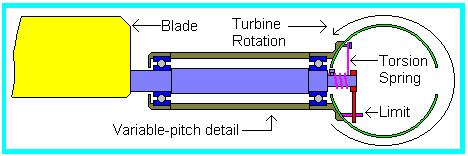
We need to
remember that those blades get use pretty fast because of the weather changes,
the sand the rain, ice, all these factor reduce the life of a blade to about
15years. 
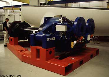
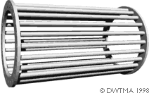
THE SHAFT
Both the primary and secondary shafts undergo
very high forces and thus have to be precisely built and tested. Their function
is to transmit the mechanical work to the generator. In the most popular, most
used and most efficient turbines there are 2 shafts. Those shafts are related
trough a gearbox which transmits and amplifies the radial speed.
Primary Shaft:
A simple shaft connected on one end to the rotor and the other end to the gearbox.
Usually it has a brake for very windy conditions so that the turbine doesn't undergo extreme conditions.
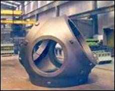
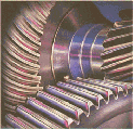
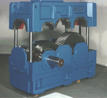
The Gearbox
It is used only on big turbines, over 15kW. It's a
power convertor, it multiplies the entering speed to
obtain a usable one
that goes into the generator. The gear box undergoes very high forces and lubrification is thus essential. Its efficiency is about
97%. Those are examples of gearbox made by FLENDER
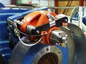
The secondary shaft
It relates the gear box to the electric generator; it can be connected to it by 3 different ways, directly, by elastic coupling or with a cardan. The elastic method is preferable since it has the capacity to absorb vibrations. Once again a disk brake system can be put on the shaft, connected to a computer to stop the turbine in extreme conditions.
THE
GENERATOR

2 Different types of generators can be used:
Asynchronous and synchronous generators.
The most used and known model is the asynchronous generator.
It uses the principle of an asynchronous motor on the other way:
The stator induces electromagnetic fields on the rotor which makes it rotate There is always a shift between the field induce by the stator and the rotor. The rotor tries to "catch up the stator". If this shift is of about 1% we say that the generator absorbs its maximal power. (15rpm for 1500rpm for ex). A slight variation of the speed induces a large variation of the power produced. The synchronism speed of a motor depends on the number of poles of the rotor and stator: 4 pôles/50 Hz(European norm) gives a synchronous speed of de 1500 rpm (most commonly used) ; 6 poles/50 Hz would give 1000 rpm.
 It is the rotor that makes the asynchronous
generator different from the synchronous generator. The rotor consists of a
number of copper or aluminium bars which are connected electrically by
aluminium end rings.
It is the rotor that makes the asynchronous
generator different from the synchronous generator. The rotor consists of a
number of copper or aluminium bars which are connected electrically by
aluminium end rings.
In the picture at the top of the page you see how the rotor is provided with an "iron" core, using a stack of thin insulated steel laminations, with holes punched for the conducting aluminium bars. The rotor is placed in the middle of the stator, which in this case, once again, is a 4-pole stator which is directly connected to the three phases of the electrical grid.
When the current is connected, the machine will start turning like a motor at a speed which is just slightly below the synchronous speed of the rotating magnetic field from the stator. Now, what is happening?
If we look at the rotor bars from above (in the picture to the right) we have a magnetic field which moves relative to the rotor. This induces a very strong current in the rotor bars which offer very little resistance to the current, since they are short circuited by the end rings.
The rotor then develops its own magnetic poles, which in turn become dragged along by the electromagnetic force from the rotating magnetic field in the stator.
Those explanations are taken from
winpower.org.
Synchronous generators:
In a synchronous generator the rotor has the same speed as the electric field rotation around the stator.
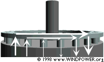
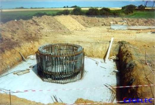
THE TOWER
The dimension of the tower that holds the turbine is mainly calculated in function of the mass of the blades and rotor and the conditions around the turbine. 21221m1219v It is fixed in the ground by huge foundations with concrete and steel. The transformer used to plug it to the electrical network is usually placed next to its base.
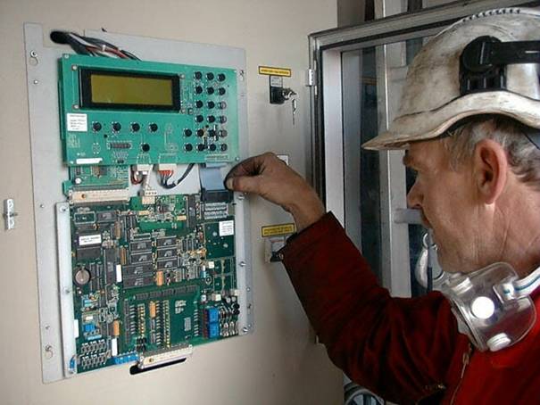
CONNECTION TO ELECTRICAL NETWORK
The wind is neither constant nor regular; in addition to that, electrical energy can hardly be stored and the electrical network can't be disturbed by such an inconstant source of energy. Therefore the connection to the electrical network is delicate.
We usually find 2 closets in the tower of a wind power turbine:
A low tension for the power to travel.
A low current which controls the different information about the system's behaviour.
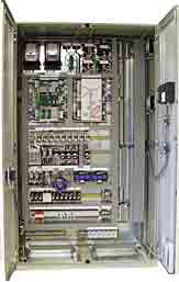
The low tension closet has a system that connects the generator directly to the electrical network with respect to its quality and the wind parameters.
The low current closet contains a computer that controls many numerical and analogical
inputs and outputs. It deals with the problems, from the weather or the turbine itself and supplies information about the energy production etc. In the case of fields of turbines, the computers can be connected together but still have to be checked once a day by an technician for a better efficiency.
Here is the basic situations that the computer has to deal with:
Wind power < 4m/s: wait until the blades can rotate.
Wind power from 4m/s to 14m/s: normal energy production until rated power is reached.
Wind power from 14m/s to 25m/s: regulation of the production to stick to the rated power.
Wind power > 25m/s: the turbine has to stop.
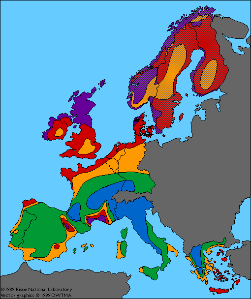
Here is the
Kappel site in
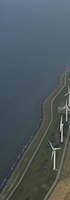
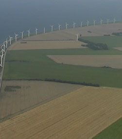
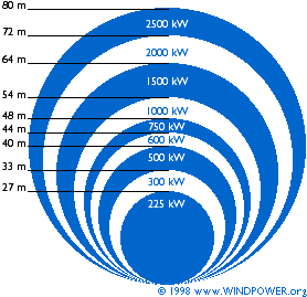
GEOGRAPHIC REPARTITION
A very
important part of the efficiency of a turbine is the conditions it is going to
undergo and the type of wind it's going to face. Here is an idea of how
II PRINCIPLES OF A WIND POWER TURBINE BEHAVIOUR
We must keep in mind that wind is something that changes a lot, and is neither stable nor reliable. Nevertheless if we want to use it to supply electricity we need it not to cause trouble to the electric network. The different types of winds we can have, their different power are many parameters that have to be taken in account: The wind blades have to be able to undergo such forces. The size of the huge turbines we are used to see is mainly due to the fact that they have to adapt to the force of the wind in the larger range possible.
Energy:
The basic use of a wind power turbine is to convert the kinetic energy of the wind into circular energy by the rotor which is then converted, once again in electrical energy by the generator with some losses in thermal energy (as materials heat.). Logically all the energy provided by the wind can't be converted into the electrical because of the mechanical interactions that induce friction and thus energy losses.
The units used to measure a turbine's performances are the kWh or even the MWh for the bigger ones.
A wind power turbine is a machine that changes the wind's kinetic energy into mechanical or electrical energy. The power supplied by such a turbine is given by the following formula:
P = ½ (rho) A V^3 Cp
With:
rho: weight of air per unit volume ( 1.225 Kg/m^3 at 15°C and pressure of 1013 mBar)
A: Area of the circle done by the blades when revolving around the axis in m²
V: velocity of wind in m/s
Cp: is a coefficient based on many parameters such as materials used in the blades, type of step up gear's efficiency.
This formula is derivate from the Betz Law:
Betz assumed that the wind is deviated form its direction as it approaches the turbine. 21221m1219v
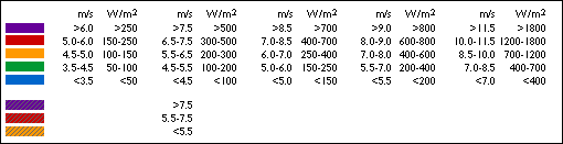
In
addition to that the rotor changes the value of the wind's velocity such that:
the wind before the turbine has a higher speed that the wind after it, which is
logic since the rotor uses some energy to rotate. But the ma ss of air that
goes through the blades stays constant, therefore the repartition of air is
about as shown here:
The
pressure is about like that around the rotor:
the distance to the rotor is on the X axis and the atmospheric pressure is
represented on the Y axis
 As the
wind approaches the rotor, atmospheric pressure increases until the air reaches
the rotor. Behind the rotor the pressure is very low until it reaches the
atmospheric value again. There are many ways to influence the type and
direction of wind by making different spatial organisation of the turbine like
the field one for example where the induced tube of the turbine at the front is
used for the one behind.
As the
wind approaches the rotor, atmospheric pressure increases until the air reaches
the rotor. Behind the rotor the pressure is very low until it reaches the
atmospheric value again. There are many ways to influence the type and
direction of wind by making different spatial organisation of the turbine like
the field one for example where the induced tube of the turbine at the front is
used for the one behind.
Let's assume that the average velocity of the wind that goes through the
blades' swept area, is equal to the average V1 (velocity before the rotor) and
V2 (velocity after the rotor):
(V1+V2) / 2
The mass of air that crosses the swept area in one second is:
m = ρF (V1+V2) / 2
where m is the mass per second, ρ is the density of air and F is the swept
area.
The power obtained by the turbine is:
P = ½ m ( V1² - V2²) which
is obtained from the second law of
From those 2 equations we can get a 3rd one:
P = 1/4 ρF (V1+V2 V1² - V2²)
If we compare this expression with the one obtained for a flux of air which is
not disturbed by a turbine we get:
The ratio between the 2 powers gives us a graph:
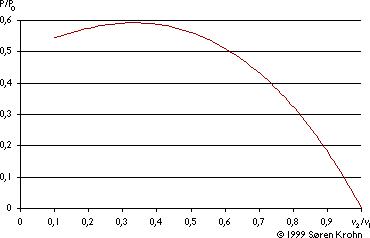
From this graph we can see that the only usable part of the power of the wind is 0.59 or 16/27 of the total power supplied by the wind.
From earthlink.net we can have a precise idea of the power supplied by a 16kW turbine with respect to the wind speed:
Wind Power and Yield Calculations
Electric power from a windmill
= (.0049)(wind speed)3(swept area)(efficiency)
where wind speed is in miles per hour
swept area is
square feet swept by windmill blades
efficiency is
%/100 for windmill, generator, and PWM regulator.
Since wind is so variable, average
wind speed is used to predict duration at each speed, which follows the
statistical distribution:
Probable time at wind speed V
= V / Vavg2
* exp(-.785 * V2 / Vavg2)
where total time is 720 hours/month
Vavg is the average wind speed at the windmill.
Power (kw at V), probable time at wind speed (hours at V), and their product (kwh at V), are plotted (for Vavg= 10 mph) vs. wind speed V (mph) in the figure shown at right.
Blades begin to feather at wind speeds above 30 mph, causing generated power to remain practically constant at feathered wind speeds.
Yield (green area in this figure) is not appreciably lessened (red area) by blade feathering. However, compared to fixed blades (dashed blue curve), peak power that must be handled by the entire system is only about 20% as high. Also, feathered blades with self-limited spin speed greatly reduce mechanical stress on all windmill parts (compared to fixed blades, with turbine shaft spinning at essentially one speed, or locked during low and high winds).
For a windmill that sweeps 300 square feet, with 10 mph average wind speed (5 mph average for locale, doubled by building aerodynamics), and overall efficiency of 40% for windmill, generator, and PWM regulator, we get:
Power
generated at 10 mph = 588 watts from each windmill
Yield from wind power = 729 kwh/month from each
windmill
Maximum generated power (limited to level at 30 mph wind speed) = 16 kw from each.
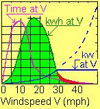 If the building aerodynamics can
result in 20 mph average wind speed at the same windmill, we can get yields of
about 5,000 kwh/month, from the same windmill, having
the same 16 kw maximum.
If the building aerodynamics can
result in 20 mph average wind speed at the same windmill, we can get yields of
about 5,000 kwh/month, from the same windmill, having
the same 16 kw maximum.
We can now get interested in the shape, the design of the blades. We saw that they were very important for the capacity of the turbine to adapt to the different types of winds.
To calculate the dimensions of those huge blades, some laws have been found from human experience:
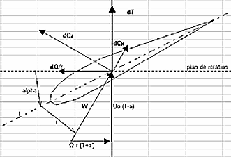 This blade looks like the shape of an
airplane's wing ; if the relative wind is W, it is
composed from the natural wind U and the wind created by the turbine itself rΩ.
This blade looks like the shape of an
airplane's wing ; if the relative wind is W, it is
composed from the natural wind U and the wind created by the turbine itself rΩ.
dCx is Uo natural wind
dCz is r radius
dT Ω angular speed
dQ elementary couple of the blade I angle
i incidence a axial induction coefficient
a' radial induction coefficient alpha
 The
relative wind has an incidence i with respect to the
blade's axis, this axis being oriented alpha with respect to the rotation
plane;
The
relative wind has an incidence i with respect to the
blade's axis, this axis being oriented alpha with respect to the rotation
plane;
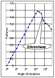
Angle I is the sum of alpha and incidence angle i.
The relative wind W generates an elementary "poussée" dCz and an elementary drag dCx. The force dCz tends to make the blade rotate. The couple given by the forces dCx and dCz is equivalent to the one created by dQ/r and dT with dQ elementary couple produced by the blade and dT elementary drag. The elementary power is deduced:
dP = dQ Ω
Once the power stored in the generator, we need to put it in phase with the one used and provided on the network: 50Hz for the Europeans. This part is done by a computer which controls the production with respect to the power of the wind. Wind turbines may be designed with either synchronous or asynchronous generators, and with various forms of direct or indirect grid connection of the generator.
Direct grid connection mean that the generator is connected directly to the (usually 3-phase) alternating current grid.
Indirect grid connection means that the current from the turbine passes through a series of electric devices which adjust the current to match that of the grid. With an asynchronous generator this occurs automatically.
|
