ALTE DOCUMENTE
|
||||||||||
If the shapes that come with TriSpectives aren't what you need for a particular model, create your own using the 3D custom shape tools. Use these tools in concert with the 2D drawing tools to create a two-dimensional cross-section, and then let TriSpectives extrude, spin, sweep, or loft it into the third dimension.
Although TriSpectives is primarily for 3D modeling, you can also create 2D shapes on the scene or page and leave them in two dimensions.
This chapter consists of two main sections. The first explains how to create 2D shapes. The second explains how to make these 2D shapes three-dimensional.

For more examples of creating 3D custom shapes for your models, see Chapter 9, "Examples."
The 2D drawing tools
Drawing lines, circles, and arcs
Drawing Bezier curves
The 3D custom shapes
Extruding and spinning
Sweeping and lofting
If you create 2D shapes directly on the scene or page, you cannot convert them into three dimensions. To extend 2D shapes into 3D, use the 2D drawing tools in tandem with the 3D custom shapes tools. We explain the custom tools later in the chapter.
Use the 2D Drawing toolbar to create 2D graphics or to construct 2D cross-sections that TriSpectives extends into 3D.
If this toolbar isn't showing,
select Toolbars from the View menu.
In the resulting dialog box, check the box next to 2D Drawing and then choose
OK.
![]()
2D Drawing toolbar
The following sections explain how to draw 2D shapes. Regardless of whether they will remain in 2D or be extended into 3D, you use the same methods to draw the shapes.
Note: The following sections on 2D shapes assume that the Angle-Distance Drag Mode tool is not selected. When it is selected, the method for drawing 2D shapes changes. We explain this tool (the one on the far right in the preceding illustration) later in this chapter.
Before you start drawing 2D shapes, create a new scene.
u To add a new scene:
Choose Scene from the Insert menu.
On the Insert Scene dialog box, choose As new scene in WorkBook.
Choose OK to see a blank scene in the TriSpectives window.
|
|
Use the Line tool to draw a line or a s 19519q168t eries of connected lines that form triangles, rectangles, and so on. You can leave these shapes in 2D or have TriSpectives extend them into the third dimension. |
In the next example, you'll draw directly on the scene. When you do so, TriSpectives cannot turn your work into a 3D IntelliShape.
u To draw lines and 2D polygonal shapes:
Select the Line tool.
The mouse pointer changes to a cross hair when you move it into the scene.
To draw a line, click and drag the mouse.
An orange line appears as you drag. A four-sided, white border surrounds the line.
To end the line, click the mouse again.
Add more lines to the first one to form a polygonal shape.
Repeat Steps 2 and 3 to draw as many lines as necessary for a triangle or other polygon. Begin the second line by clicking in the same spot you clicked to end the first line. When you're over this spot, a green dot appears. If you don't use the green dot, your lines will probably be discontinuous.
The line in progress appears in orange. If you think you've finished a line but it still appears in orange, go back and click its endpoint to define it. Completed lines appear in green by default, although you can change this outline color if you want. See "Assigning colors and line styles to 2D shapes" later in this chapter.
To complete a polygonal shape, end the last line by clicking on the beginning point of the first line.
|
|
If all the lines are connected, the shape fills with a color. If not, use the Window Zoom tool to more closely inspect the corners of the shape. Click the line and then drag its red handle over the handle of the other line. |
|
|
When you successfully match up the endpoints, the shapes fills with color. Use the Fit Scene tool to return to a normal view. If you drew a four-sided shape, for example, it might look like this: |
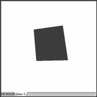
2D shape
Just as you can change the outline color for 2D lines and shapes, you can change the fill color. See "Assigning colors and line styles to 2D shapes" later in this chapter.
To draw squares, rectangles, and other shapes that require precise measurements, you can tell TriSpectives to report distance measurements in the 2D Drawing properties sheet. To show both the distances and angles of shapes you draw, use the Angle-Distance Drag Mode tool. For details, see "Measuring 2D angles and distances" later in this chapter.
Next we'll use a tool that smooths the corners of polygonal shapes. This tool is called the fillet.
|
|
Use the Fillet tool to round off the corners of a 2D square or other polygonal shape. You can think of the Fillet tool as the 2D counterpart to beveling. |
In the following example you'll smooth the corners of the shape you just drew.
u To round off the corners of 2D polygons:
Select the Fillet tool.
Place the mouse pointer on the corner you want to round off.
Click the corner and drag toward the center of the shape.
The more you drag, the more rounded you make the corner.
To round off another corner, place the mouse pointer on it and repeat Step 3.
The following illustration shows the Fillet tool's handiwork.
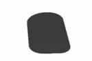
2D shape with filleted corners
When you drew the polygon in the previous example, you were working on a plane in 3D space. By default, this plane is parallel to the scene grid. For an illustration, turn on the scene grid and use the Orbit Camera tool to look at the 2D drawing and the scene grid edgewise.
If you prefer to work while looking directly at the 2D drawing, use the Look At tool and point to the drawing you created.
In addition to drawing polygonal shapes, you can draw circles and half-circles (arcs). This section shows you how.
If your scene already contains 2D shapes, click anywhere in the scene outside their borders to deselect the shapes. If you don't, the new shape will have the same border as the last active shape.
u To draw a circle:
|
|
Select the Circle tool. |
Click the mouse pointer in the scene and then drag to form the circle.
The point where you click becomes the center of the circle. You drag along its radius. The point where you release the mouse becomes the perimeter of the circle.
|
|
To see the circle's handles, choose the Select tool or click the Circle tool again to turn it off. |
Drag one of the square handles to change the diameter of the circle. Drag the other square handle to make the circle an oval.
u To draw an arc:
|
|
Select the Arc tool. |
Click the pointer in the scene and drag to form the arc.
Release the mouse when you finish. A newly created arc is always half a circle. If you want to close the arc shape, use the Line tool to connect its ends.
If you want an arc that is not half a circle, change the arc's radius. See "Editing 2D shapes" later in this chapter. The section also explains splitting a curve and deleting curve segments.
|
|
Use the Bezier tool to create a spline, or a Bezier curve. Splines are lines that contain multiple curves. You'll find splines useful, for example, in creating architectural ornamentation such as cornices and moldings. Later in this chapter, you'll use Bezier curves to help make a 3D plunger and a 3D table leg. |
u To draw a Bezier curve:
Select the Bezier tool.
Click the pointer in the scene to start the line, move to the endpoint of the line, and click again to finish it.
The first line is straight. You can either click the pointer again and define a series of curved, connected lines, or you can stop and add curvature to the first straight line.
|
|
To see the handles for each line you draw, choose the Select tool or click the Bezier tool again to turn it off. |
Each line has round handles at the ends and two square handles between.
Click and drag the square handles to form curves or to adjust the curves you've already created.
Make the curves more severe or subtle by experimenting with the handles. To see illustrations of a Bezier curve before and after dragging the handles, see the "Spinning" section later in this chapter.
Like 3D IntelliShapes, 2D objects have different editing modes. In the 2D realm, the modes are Curve mode and Shape mode.
Curve mode. When you finish drawing a shape or curve and then turn off the drawing tool, you're in Curve mode. To reform the curves of your shape, drag the handles of the curves.
In Curve mode, you can edit shapes in two other ways. Both are available when you right-click a curve and use the pop-up menu.
If you choose
If you select Edit Curve from the pop-up menu, the resulting dialog box lets you specify various dimensions of the curve. Your options depend on the type of curve you choose.
Line: Specify the slope angle and length of the line.
Circle: Specify the major and minor radius and orientation angle.
Arc: Specify the radius, flip its center, and swap its endpoints.
Bezier: Set the slope angle and magnitude of both tangents.
Note: The
Shape mode. After you click elsewhere to cancel the selection of a shape or curve, the first click on a shape or curve puts you in Shape mode. A white sizebox appears around the shape or curve, just like in 3D. You can resize the shape or curve by dragging its square handles, but its aspect ratio remains the same. You can also resize the shape by clicking a sizing handle, selecting Edit Value from the resulting menu, and typing a new size in the dialog box.
Note: If a 2D shape or curve is active when you create another, they are assigned to the same sizebox. Once you're in Shape mode, your commands affect every shape or curve in the sizebox.
To delete all the shapes in a sizebox, right-click on one of the shapes in Shape mode and then select Delete from the menu.
If you're in Curve mode, you can only delete one curve of a shape at a time. Right-click on the curve and select Delete from the menu. If you're in Curve mode and have previously split a curve into two or more segments, you delete only the segment you select. This allows you, for example, to create an arc that is neither a semi-circle or a full circle.
You can also delete a selected shape or curve by pressing the Delete key.
As you've learned by now, TriSpectives treats a 2D shape much like a 3D IntelliShape. When you right-click on a 2D shape, you have access to its shape and style properties, just like in 3D. You can specify the dimensions of the shape's sizebox, make the 2D shape transparent, assign it a color or texture, and so on.
Except for the two differences we describe below, 2D shape and style properties are identical to those for 3D IntelliShapes. For details on these properties, see Chapters 2 and 3 of this user guide and Chapter 3, "Dialog boxes," of the TriSpectives Reference Guide.
You can also use the Camera tools with 2D shapes, although the effect is like moving a piece of paper.
To see numerical values for the outlines of your 2D shapes,
right-click the shape, select 2D Shape Properties from the pop-up menu, and
then click the Outlines tab. The resulting table looks like a spreadsheet. The
first line shows the starting coordinates of the
2D outline. Subsequent rows of the table describe each shape in the outline.
The meaning of the numbers depends on the types of shapes you use.
If you selected a shape that shares a sizebox with other shapes, you can see the outlines for the other shapes using the drop-down list below the table. For more information on this property sheet, see Chapter 3, "Dialog boxes," of the TriSpectives Reference Guide.
Colors in 2D shapes are slightly different than in 3D, because you can assign different colors to the shape's border and its filling.
To assign a fill color, right-click the shape, select Style Properties from the pop-up menu, and then click the Fill Color tab. The resulting property sheet looks and works like the Color property sheet for 3D IntelliShapes. For more details, see "Colors" and "Textures" in Chapter 2, "IntelliShapes."
To assign a color to the shape's border, right-click the shape, select Style Properties from the pop-up menu, and then click the Line Style tab. In the resulting property sheet, you have the following options:
Assign a border color by clicking one of the palette squares.
Assign a border pattern by clicking the Line Pattern box and then choosing a solid or dotted line from the resulting list.
Remove the fill color from the shape by clicking the check box and deleting the mark next to Fill outlines.
If you look through the 3D forms in the Shapes catalog and don't find what you need, you can start creating a new shape in two dimensions and then let TriSpectives take care of the third one for you. Use the custom shape tools on the 3D Shapes toolbar.
If these tools aren't showing, select Toolbars from the View menu. In the resulting dialog box, check the box next to 3D Shapes and then choose OK.
![]()
Custom shape tools
|
Create 2D cross-sections and then let TriSpectives extend them into 3D. |
Although their
results are different, all the custom shape tools operate on the same
principle. You start by drawing a 2D |
TriSpectives has four methods for transforming closed 2D cross-sections into 3D:
Extruding, or creating a 3D shape by simply adding height to a single cross-section you create.
Spinning a single cross-section around the
vertical axis to create a
3D shape.
Sweeping one cross-section along a path to create a 3D shape.
Lofting a series of cross-sections along a path. TriSpectives blends the cross-sections to create the 3D shape.
The following sections describe each method. You'll make a 3D shape in each example.
To extrude a 2D cross-section into three dimensions, TriSpectives pulls it along a third axis to give it height. In this way you can create a cube from a square, or a cylinder from a circle.
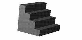
In the following example, you'll create a set of stairs. We used a similar procedure to create the stairs in the Collage catalog.
When you're done, you'll see how convenient extrusion is. Without it, you'd have had to build the stairs using a series of slab shapes, resizing each until they looked right. With extrusion, you draw one shape and then let TriSpectives do the rest.
u To use the extrusion technique to build a set of stairs:
Create a new scene in your WorkBook.
|
|
Select the Extrude Shape tool on the 3D Shapes toolbar. |
Click in the scene.
TriSpectives displays the Extrude Shape Wizard. On page 1, you can choose to extrude the new shape along the surface of another shape, or away from its surface. On page 2, you can add the new 3D shape to the first shape, create a hole in it, or create a stand-alone shape.
Because we're creating a stand-alone shape, you can ignore the wizard in this case. For an example of creating a 2D cross-section on the surface of another shape, see "Sweeping" later in this chapter.
Select Finish on the wizard to close it.
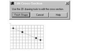
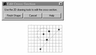
TriSpectives displays a grid and a dialog box called Edit
Cross-Section. You'll use the grid to draw
the stair shape.
|
|
Tip: Drag the dialog box out of the way so it doesn't interfere with your work on the grid. You should also select the Look At tool and then click the grid to view it straight on. |
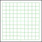
2D grid
|
|
Select the Line tool and move the mouse pointer to the grid. |
The pointer changes to a cross hair.
Draw a continuous polygonal shape that resembles stairs as viewed from the side.
To keep the stairs evenly sized, make each one the width and length of one grid mark. To make sure the lines are connected, use the green dot. If you don't use the green dot, your lines will be discontinuous and TriSpectives will be unable to extend the cross-section into 3D.
If you need help drawing the shape, see "Drawing lines and 2D polygonal shapes" earlier in this chapter. When you're finished, your grid should look like the following illustration.
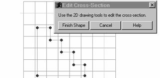
Stair shape in 2D grid
If necessary, edit the cross-section.
If you're not satisfied with the cross-section, you can edit it on the grid. You have a number of options:
Drag the handles on the cross-sections to reform it.
To insert a new line within the cross-section,
right-click on the line at the location you want a new point, and then select
To specify dimensions for a line in the cross-section, right-click on the line and select Edit Curve from the pop-up menu. The resulting dialog box lets you specify various dimensions of the line or shape.
To delete a line or shape, right-click on it and select Delete from the pop-up menu. To cancel the entire operation, select Cancel.
To extrude the 2D cross-section into 3D stairs, select Finish Shape on the Edit Cross-Section dialog box.
You can also right-click the cross-section and select Finish Shape from the pop-up menu. In either case, TriSpectives extends the cross-section into 3D. Your stairs are done.
Stairs extruded from 2D
|
|
If you're still not satisfied with the shape of the cross-section you created, you can edit it even though the shape is in 3D. Select the Edit IntelliShapes tool, right-click on the stairs, and then select Edit Cross-Section from the pop-up menu. Repeat Steps 7 and 8 to revise the cross-section. |
Use the spinning method to create a shape by rotating a 2D profile around its vertical axis. For example, when you create a cross-section of a right triangle (one with a 90 angle at its base), TriSpectives can spin it into a cone.
Because TriSpectives spins the cross-section around its vertical axis, the resulting 3D shape always has a circular nature. In the following example, you'll create the rubber fitting for a drain plunger.
u To create a plunger shape by spinning:
Create a new scene in your WorkBook.
|
|
Select the Spin Shape tool on the 3D Shapes toolbar. |
Click in the scene.
TriSpectives displays the Spin Shape Wizard. On page 1, you can choose to spin the new shape along the surface of another shape, or away from its surface. On page 2, you can choose to add the new 3D shape to the first shape, create a hole in it, or create a stand-alone shape.
Because we're creating a stand-alone shape, you can ignore the wizard in this case. For an example of creating a 2D cross-section on the surface of another shape, see the next section, "Sweeping."
Select Finish on the wizard.
TriSpectives displays a grid and the Edit Cross-Section dialog box. You'll use the grid to draw the plunger shape.
|
|
Tip: Drag the dialog box out of the way so it doesn't interfere with your work on the grid. You should also select the Look At tool and then click the grid to view it straight on. |
|
|
|
Select the Bezier tool and move the mouse pointer to the grid, about two squares right of the vertical axis. |
|
The pointer changes to a cross hair.
Click and drag to draw a line on the grid, and then select the Bezier tool again to turn it off.
Your line should look like this.
Bezier line before curving
Drag the square tangent handles to create the Bezier curve.
Drag the top handle toward the vertical axis and the bottom handle away from it. As you drag, do not pass over the vertical or horizontal axes of the grid. The axes are the thicker white lines.
You can also drag the
endpoints of the line to reposition it.
If you need help drawing the curve, see "Drawing Bezier curves" earlier in this
chapter.
When you're done, the curve should look like this:
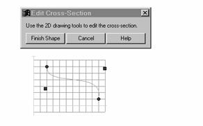
Bezier curve
|
|
Click the Line tool and place the mouse pointer over one of the endpoints of the Bezier curve. |
When a green dot appears, your pointer is directly on the endpoint. You can now enclose the shape. If you don't use the green dot, your lines will be discontinuous and TriSpectives will be unable to extend the cross-section into 3D.
Draw three lines to enclose the shape, as shown below.
If you need help drawing the lines, see "Drawing lines and 2D polygonal shapes" earlier in this chapter. When you're finished, the cross-section should look like the following illustration.
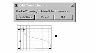
Finished cross-section
Note the space between your cross-section and the vertical axis. When TriSpectives spins the cross-section, it makes this space a hole in the center. If you don't want a hole, the cross-section you create must be flush with the vertical axis.
If necessary, edit the cross-section.
If you're not satisfied with the cross-section, you can edit it on the grid. You have a number of options:
Drag the handles on the cross-sections to reform it.
To insert a new curve within the cross-section,
right-click on the curve at the location you want a new point, and then select
To specify dimensions for a line in the cross-section, right-click on the line and select Edit Curve from the pop-up menu. The resulting dialog box lets you specify various dimensions of the line or shape.
To delete a line or shape, right-click on it and select Delete from the pop-up menu. To cancel the entire operation, select Cancel.
To spin the 2D cross-section into a plunger fitting, select Finish Shape on the Edit Cross-Section dialog box.
You can also right-click on the cross-section and select Finish Shape from the pop-up menu. In either case, TriSpectives extends the cross-section into 3D and creates a plunger fitting. If you wanted, you could add a cylinder shape to the hole and finish the plunger.
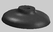
Plunger fitting spinned from 2D
|
|
Select the Edit IntelliShapes tool and then select the shape. |
When you spin a 2D profile, the resulting 3D shape has an extra, square handle. This handle lets you turn the 3D shape around its vertical axis and remove a slice of the shape. For more details, see "The square handle" in Chapter 2, "IntelliShapes."
Right-click on the plunger fitting and select Edit Cross-Section from the pop-up menu.
The cross-section and grid appear again. If you wanted, you could edit the cross-section using the explanations in Step 10. When you view the cross-section against the spinned shape, you get a better idea for how TriSpectives performed the operation.
You can also use the sweeping process to create a 3D shape, just like the extrusion and spinning methods described earlier. In those methods, TriSpectives moved the 2D profile along a set path, and all you had to do was create the cross-section.
With the sweeping method, you determine the path as well as create the cross-section. The path can be a line, a series of lines, a Bezier curve, or an arc.
In this example we'll create a curved table leg. First you'll create a square cross-section, and then you'll sweep it along a path made from a Bezier curve.
u To create a 3D shape through sweeping:
|
|
Create a new scene in your WorkBook and select the Edit IntelliShapes tool. |
Open the Shapes catalog and drag the Slab shape into the scene.
|
|
The slab represents the top of your table. If necessary, use the Orbit Camera tool to view the flat face of the slab. Click the Select tool when you finish with the Orbit Camera tool. |
|
|
|
Select the Sweep Shape tool on the 3D Shapes toolbar. |
|
Move the mouse pointer over the slab and release the mouse when the slab's surface is outlined in green.
This ensures that the table leg is anchored to the flat side of the table. TriSpectives displays the Sweep Shape Wizard.
Make the following selections in the wizard:
On page 1, choose to sweep the new shape away from the table top. Select Next to move to page 2.
On page 2, choose a Bezier curve as your sweep path. Select Next to move to page 3.
On page 3, choose to add material to the table top, and then select Finish on the wizard.
TriSpectives displays the Edit Cross-Section dialog box and places a grid on the slab surface. You'll use the grid to determine the length and width of the table leg.
|
|
Tip: Drag the dialog box out of the way so it doesn't interfere with your work on the grid. You should also select the Look At tool and then click the grid to view it straight on. |
|
|
|
Extend the grid over the full surface of the slab. |
|
|
You can extend the grid over the entire surface of a shape. |
Select the Project Edges to Drawing Grid tool and then click the grid. The grid extends to cover the entire face of the slab. To turn off the Project Edges to Drawing Grid tool, click it again. |
|
Note: If necessary, you can also adjust the size of the squares in the grid. Right-click the grid, select Grid Settings from the pop-up menu, and change the line separation values in the resulting dialog box. Click OK when you finish.
|
|
Select the Line tool, move the mouse pointer to the grid, and draw a square. |
To make the leg a square shape, make each side the length of two grid marks. Use the green dot to help you draw connected lines. If you need help drawing the square, see "Drawing lines and 2D polygonal shapes" earlier in this chapter.
Choose Finish Shape on the Edit Cross-Section dialog box.
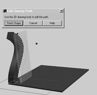
TriSpectives displays a second grid, this time along the path. You also see the Edit Sweep Path dialog box. If necessary, select the Look At tool and then click the grid to view it straight on.
|
|
You can also use the Orbit Camera tool to change your view of the grid. |
Drag the square handle of the Bezier line to the right to create a graceful, curving sweep path.
The sweep path should look like the following illustration. It is shown with the finished leg to illustrate how TriSpectives sweeps the shape into 3D.
![]()

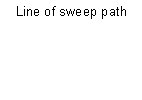
Sweep path of table leg
Choose Finish Shape on the Edit Sweep Path dialog box.
You can also right-click on the cross-section and select Finish Shape from the pop-up menu. In either case, TriSpectives moves the square along your Bezier path to create the table leg.
If necessary, drag the sizebox handles of the leg and the table to make them more proportional.
At this point you could finish the table if you wanted, using the tools explained in Chapter 3 to copy three more legs, position them on the slab, and add wood textures.
You could also edit the cross-section and sweep path, even though the chair leg is now a 3D shape. Right-click the leg and choose the appropriate editing option from the pop-up menu. When the grid appears again, you can drag the handles to edit the cross-section or path.
You've now used three methods to create custom shapes. In each, you created one closed 2D profile and extended it into 3D. In the last of the four methods, lofting, TriSpectives uses multiple profiles, which you edit and resize as necessary. TriSpectives then blends the profiles along a path you define to create the final 3D shape.
As a simple first example of lofting, you'll repeat the creation of a table leg. Not only does the example introduce lofting, it provides a contrast to the extrusion and sweeping methods. In the following example you'll use several cross-sections so the shape of the table leg changes along its path.
u To create a 3D shape by lofting:
|
|
Create a new scene in your WorkBook and select the Edit IntelliShapes tool. |
Open the Shapes catalog and drag the Slab shape into the scene.
|
|
The slab represents the top of your table. If necessary, use the Orbit Camera tool to view the flat face of the slab. Click the Select tool when you finish with the Orbit Camera tool. |
|
|
|
Select the Loft Shape tool on the 3D Shapes toolbar. |
|
Move the mouse pointer over the slab and release the mouse when the slab's surface is outlined in green.
This ensures that the table leg is anchored to the flat side of the table. TriSpectives displays the Loft Shape Wizard.
Make the following selections in the wizard:
On page 1, enter 4 as the number of
cross-sections.
Select Next to move to page 2.
On page 2, choose Custom as the type of cross-section and then select a straight line as your loft path. Select Next to move to page 3.
On page 3, choose to add material to the table top, and then select Finish on the wizard.
TriSpectives displays the Edit Loft Cross-Section dialog box and places a grid on the slab surface. You'll use the grid to determine the length and width of the table leg.
|
|
Tip: Drag the dialog box out of the way so it doesn't interfere with your work on the grid. You should also select the Look At tool and then click the grid to view it straight on. |
|
|
|
Use the Window Zoom tool to zoom in on the origin of the grid - the intersection of the heavier white lines. |
|
Change the grid settings to alter the spacing between grid marks.
Right-click the scene background, select Grid Settings from the pop-up menu, enter 6.0 as the vertical and horizontal grid line separations, and then click OK.
|
|
Click the Line tool and make the first cross-section. Create a square of two grid cells by two grid cells. The center of the square should be the origin of the grid. |
Now create the rest of the cross-sections, as described in the next few steps.
u To create the rest of the cross-sections for the loft shape:
Select Next Section on the Edit Loft Cross-Section dialog box to proceed to cross-section #2.
Change the grid settings for the new cross-section.
Right-click the scene background, select Grid Settings from the pop-up menu, enter 5.0 as the vertical and horizontal grid line separations, and then click OK.
Right-click the scene background again and select Cross-Section Properties from the pop-up menu.
Change the relative distance from the start of the path of this cross-section to 0.1 (in other words, 10% of the total length).
The beginning section of the loft is at 0.0; the end is at 1.0.
|
|
Click the Line tool and make the second cross-section. Create a square of two grid cells by two grid cells. |
Select Next Section on the Edit Loft Cross-Section dialog box to proceed to cross-section #3.
Repeat Steps 2 through 4 for the third cross-section, but make the grid separations 4.0 and the relative starting distance 0.5.
|
|
Select the Circle tool and make the third cross-section. Create a circle whose center is at the origin of the grid. Make the radius about 4.0 (in other words, the size of one grid cell). |
Select Next Section on the Edit Loft Cross-Section dialog box to proceed to cross-section #4.
Repeat Steps 2 through 4 for the fourth cross-section, but make the grid separations 2.0 and the relative starting distance 0.5.
Select the Circle tool again and make the fourth cross-section.
Create another circle whose center is at the origin of the grid. Make the radius about 2.0 (in other words, the size of one grid cell).
Select Finish Shape on the Edit Loft Cross-Section dialog box.
Use the Fit Scene tool, the Orbit Camera tool, and the Window Zoom tool to inspect the results. The leg you created varies from a box at the table top to a more slender, circular shape.
You can use the sizebox handle at the end of the leg to change its length as necessary.
You can also modify the leg design in a number of other ways, as you'll see when you right-click on the leg while in IntelliShape mode. The pop-up menu includes a number of editing options:
Show Cross-Sections.
Edit Path.
Edit Match Points.
IntelliShape Properties.
For example, try the Show Cross-Sections option. This selection displays the cross-sections, each with its own number. If you right-click on a number, another pop-up menu appears. This menu gives you the following options:
Edit the cross-section.
Insert a new cross-section.
Delete the cross-section.
Modify the cross-section's properties, including the relative position of the section along the path and its angular position about the grid origin.
Because the lofting method is so rich in features and possibilities, you'll need to practice with the various options to master the techniques. Consult the TriSpectives Reference Guide for more information.
Our final example is the teapot shown in the following illustration. We provide general instructions for how we created it, if you'd like to duplicate it.
To create the teapot, we used three of the four methods for developing custom shapes.
The main body of the teapot is a cross-section that we brought into 3D using the spinning method. The cross-section, from top to bottom, consisted of a slightly tilted arc, five Bezier curves, and straight lines along the bottom and vertical axis.
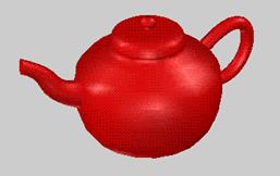
We created the handle of the teapot by sweeping a circular
cross-section along a Bezier-curve path. We used the TriBall tool to orient the
plane of the path into a vertical position, and then adjusted the Bezier curve
so its end and beginning penetrated the surface of the pot. To arrive at the
final handle shape, we revised the Bezier curve and the size of the circular
cross-section until it looked right.
We created the spout by lofting originally circular cross-sections along another Bezier-curve path. First, we positioned the spout opposite the handle. Next, we used the TriBall tool to rotate the plane of the path to a vertical position. Then, we adjusted the circular cross-sections to make them progressively smaller as we moved farther from the body, and gradually more elliptical with a longer vertical axis. To create a more graceful curve, we revised the Bezier-curve path.
While creating each part of the teapot, we visually judged whether the shapes were correct. If you need more precision when creating models, you can use tools such as the TriBall and SmartDimensions. See Chapter 3 for details on using both tools.
Try creating your own teapot or another combination of custom shapes. Extrusion, spinning, sweeping, and lofting are powerful tools that you can master with a little practice.
|
|
Use the Mirror Curve tool to create a duplicate image of a 2D cross-section before extending them both into three dimensions. The following steps show you how to use the tool to create a pair of cylinders. |
u To create identical custom shapes using the Mirror Curve tool:
Create a new scene for this example.
|
|
Select the Extrude Shape tool on the 3D Shapes toolbar and then click Finish on the Wizard dialog box. |
Although we use extrusion for this example, you can mirror curves using any custom shape method.
|
|
Click the Look At tool and then click the grid to view it straight on. |
|
|
Select the Circle tool and then draw a circle on the grid. |
|
|
Click the Line tool and then draw a line on the grid to represent the axis of symmetry (the mirror line). |
TriSpectives will create the duplicate shape on the other side of this line. Your grid might look like the following illustration.
Circle with mirror line
Click the Line tool again to turn it off.
Right-click on the mirror line and select Use Outline for Construction Only from the pop-up menu.
This step eliminates the mirror line from being extended into 3D. You're only using it to construct the 3D shape.
Select all the shapes in the cross-section, including the mirror line.
Click a shape, hold down the Shift key, and click all the other shapes, including the mirror line. If you create a shape using the Line tool, click each line in the shape.
|
|
Select the Mirror Curve tool and then click the mirror line. |
TriSpectives duplicates the circle symmetrically on the other side of the axis.
Choose Finish Shape on the Edit Cross-Section dialog box.
TriSpectives extrudes both circles into 3D cylinders.
If your 2D shapes and cross-sections must conform to certain specifications, you can measure their angles and distances as you create them. By default, these measurement tools are off.
u To show measurements for your 2D shapes and cross-sections:
Select Options from the Tools menu.
Click the 2D Drawing tab in the dialog box that appears.
In the 2D Drawing properties sheet, click the check box next to Show Snap and Measurement Feedback.
Click OK to close the dialog box.
Now when you draw 2D shapes and cross-sections, TriSpectives tells you the distance covered by your drawing.
|
|
For example, select the Line tool
and draw a line. The numbers that appear show the length of the line relative
to the x-axis and the |
|
|
If you want to see measurements for both the distance and angles of your 2D shapes, select the Angle-Distance Drag Mode tool. |
When you select this tool, the method for drawing 2D shapes changes slightly. The next few steps, for example, show you how to draw a line.
u To draw lines when the Angle-Distance Drag Mode tool is selected:
Select the Line tool, move your pointer to the scene, and begin drawing your line.
TriSpectives shows the angle of the line as you drag.
When the angle of the line is correct, click the mouse.
To see the distance measurement for the line, resume dragging.
With the angle now set, TriSpectives shows the current distance of the line as you drag.
When the distance is correct, click the mouse to finish defining the line.
|
|
The Arc and Bezier tools use corresponding drawing methods when the Angle-Distance Drag Mode tool is selected. Try them. |
When you complete a 2D cross-section and extend it into 3D, you can view and revise some of its characteristics with the Cross-Section property sheet.
u To view cross-section properties of a 3D shape you began in 2D:
|
|
Select the Edit IntelliShapes tool. |
Right-click the 3D shape and select IntelliShape Properties from the pop-up menu.
Click the Cross-Sections tab at the top of the resulting dialog box.
The cross-section properties for the selected shape appear. For details on these properties, see Chapter 3, "Dialog boxes," in the TriSpectives Reference Guide.
|
