|
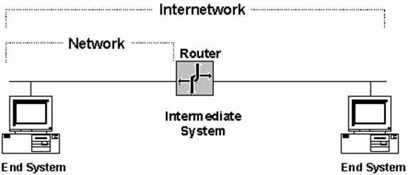
Windows NT Server Abstract With Windows NT Server 4.0, the implementation and configuration of routing has become much easier. Windows NT Server 4.0 is well-suited for branch office deployments, as well as for use in edge routing where a corporate network connects to the Internet or other wide area network (WAN). In these scenarios, the configuration of the router is often left to a network administrator, rather than a network infrastructure specialist. This paper is designed to provide a technical overview of the principles of unicast routing, the routing of packets with a unicast destination address, for those who are expected to design and configure routing for their organizations. The principles in this paper apply to all commonly used internetworking protocols such as Internet Protocol (IP), Internetwork Packet Exchange (IPX), AppleTalk, and others. IntroductionUnicast routing is the process of forwarding unicasted traffic from a source to a destination on an internetwork. Unicasted traffic is destined for a unique address. To understand the details of routing protocols such as Routing Information Protocol (RIP) and Open Shortest Path First (OSPF) and their implementation in Windows NT Server version 4.0 with the Routing and Remote Access Service, it is important to have a solid foundation in the principles of unicast routing. Because Windows NT, with the Routing and Remote Access Service (RRAS), is an open platform that can conceivably host any internetworking protocol and routing protocol, this whitepaper provides an overview of protocol-independent unicast routing principles. The Internet Protocol (IP) and the Internetwork Packet Exchange (IPX) protocol are used as the example protocols where appropriate. This whitepaper is intended for network engineers and support professionals who are already familiar with internetworking protocols such as Transmission Control Protocol/Internet Protocol (TCP/IP) and IPX. Internetwork RoutingThe following terms are essential to your understanding of routing: · &nb 12412c216m sp; &nb 12412c216m sp; End Systems. As defined by the International Standards Organization (ISO), end systems are network devices without the ability to forward packets between portions of a network. End systems are also known as hosts. · &nb 12412c216m sp; &nb 12412c216m sp; Intermediate Systems. Network devices with the ability to forward packets between portions of a network. Bridges, switches, and routers are examples of intermediate systems. · &nb 12412c216m sp; &nb 12412c216m sp; Network. A portion of the networking infrastructure (encompassing repeaters/hubs and bridges/Layer 2 switches) that is bounded by a network layer intermediate system and is associated with the same network layer address. On IP internetworks, a network is also called a subnet. · &nb 12412c216m sp; &nb 12412c216m sp; Router. A network layer intermediate system used to connect networks together based on a common network layer protocol. · &nb 12412c216m sp; &nb 12412c216m sp; Hardware Router. A router that performs routing as a dedicated function and has specific hardware designed and optimized for routing. · &nb 12412c216m sp; &nb 12412c216m sp; Software Router. A router that is not dedicated to performing routing but performs routing as one of multiple processes running on the router computer. A Windows NT Server version 4.0 computer running the Routing and Remote Access Service is an example of a software router. Note that there are some hybrid routers where some routing is done in hardware and where system configuration and routing table management is done in software. A good example of hybrid routers are the exponeNT switches from Berkeley Networks which use optimized hardware for routing and Windows NT for system configuration and management. · &nb 12412c216m sp; &nb 12412c216m sp; Internetwork. At least two networks connected using routers. Figure 1 illustrates an internetwork.
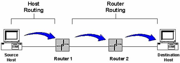
Figure 1 An example of an internetwork. Addressing in an InternetworkThe following internetwork addressing terms are also important to your understanding of routing: · &nb 12412c216m sp; &nb 12412c216m sp; Network address. Also known as a network ID. The number assigned to a single network in an internetwork. Network addresses are used by hosts and routers when routing a packet from a source to a destination in an internetwork. · &nb 12412c216m sp; &nb 12412c216m sp; Host address. Also known as a host ID or a node ID. A host address can either be the host's physical address (the address of the network interface card) or an administratively assigned address that uniquely identifies the host on its network. · &nb 12412c216m sp; &nb 12412c216m sp; Internetwork address. The combination of the network address and the host address that uniquely identifies a host on an internetwork. An example of an internetwork address is an IP address that contains a network ID and a host ID. For detailed information on how IP implements network ID and host ID addressing, see the "Introduction to TCP/IP" whitepaper. When a packet is sent from a source host to a destination host on an internetwork, the network layer header of the packet contains: · &nb 12412c216m sp; &nb 12412c216m sp; The Source Internetwork Address, which contains a source network address and source host address. · &nb 12412c216m sp; &nb 12412c216m sp; The Destination Internetwork Address, which contains a destination network address and destination host address. · &nb 12412c216m sp; &nb 12412c216m sp; A Hop Count, which either starts at 0 and is incremented for each router crossed to a maximum value, or starts at a maximum value and is decremented to zero for each router crossed. The hop count is used to prevent the packet from endlessly circulating on the internetwork. Routing ConceptsRouting is the process of transferring data across an internetwork from a source host to a destination host. Routing can be understood in terms of two processes, host routing and router routing. Host routing occurs when the sending host forwards a packet. Based on the destination network address, the sending host must decide whether to forward the packet to the destination or to a router. In Figure 2, the Source Host forwards the packet destined for the Destination Host to Router 1. Router routing occurs when a router receives a packet that is to be forwarded. The packet is forwarded between routers (when the destination network is not directly attached to the router) or between a router and the destination host (when the destination network is directly attached). In Figure 2, Router 1 forwards the packet to Router 2. Router 2 forwards the packet to the Destination Host. If your browser does not support inline frames, click here to view on a separate page.
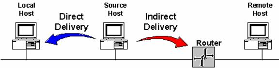
Figure 2 The routing process. Host RoutingWhen a host using a routable protocol wants to send data to another host, it must first obtain the internetwork address of the destination. The destination internetwork address is obtained through an address resolution process whereby the sending host obtains the destination internetwork address by referencing its logical name. For example, TCP/IP hosts use Domain Name System (DNS) name resolution to resolve a DNS domain name to an IP address. Novell NetWare workstations query the bindery (a database stored on a NetWare server) or the NetWare directory tree of their default server to resolve a server name to its IPX internetwork address. Once the destination internetwork address has been obtained, the source network and the destination network addresses are compared. When the source and destination hosts are on the same network, the packets are sent directly to the destination host by the source without the use of a router. The source host sends the packet to the destination by addressing the packet to the destination's physical address. This is known as a direct delivery. In a direct delivery, the destination internetwork address and the destination physical address are for the same end system. Conversely, when the source and destination hosts are on different networks, the packets to the destination cannot be directly delivered by the source. Instead, the source delivers them to an intermediate router by addressing the packet to the router's physical address. This is known as an indirect delivery. In an indirect delivery, the destination internetwork address and the destination physical address are not for the same end system. During an indirect delivery, the sending host forwards the packet to a router on its network by determining the router corresponding to the first hop or by discovering the entire path from the source to the destination.
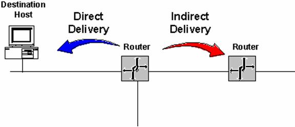
Figure 3 Host routing process. Host Determination of the First HopIP and IPX sending hosts determine the physical address of the first hop router using one of the following processes: Host Routing TableA routing table on the host will yield the forwarding address of the router to be used to reach the desired destination network ID. An example is the IP routing table on a Microsoft TCP/IP host. (See "Routing Tables" later in this whitepaper for a detailed definition of a routing table.) Dynamic Updates of Host Routing TableTCP/IP has a facility to dynamically update the host routing table with better routes as packets are sent to destinations. The Internet Control Message Protocol (ICMP) Redirect Message is a message sent by an IP router to a sending host informing it of a better route to a destination host. The better route becomes a host route in the routing table. EavesdroppingTCP/IP hosts have the ability to listen to the routing protocol traffic used by routers. This is known as eavesdropping or wiretapping. Eavesdropping hosts have the same detailed routing information as the routers. An example of eavesdropping is Silent RIP. Silent RIP is the ability of a TCP/IP host to listen to RIP for IP routing traffic exchanged by RIP routers and update its routing table. Windows NT Server 3.51 and Service Pack 2 and later and Windows NT Workstation 4.0 and Service Pack 4 and later support Silent RIP. Default RouterTo simplify the configuration of hosts and routers and to reduce the overhead associated with each host having routes for all the networks in the internetwork, a sending host is configured with a single default route. The default route and its forwarding address to the default router is used when no other routes to the destination network are found. An example of a default router is the Default Gateway configuration parameter for TCP/IP hosts. Querying the Network for the Best RouteFor hosts without a routing table or a configured default router, the sending host can determine the physical address of the first hop router by querying the routers on the network. A query for the best route to a specified destination network address is sent as a broadcast or multicast packet. The responses from the routers are analyzed by the sending host and the best router is chosen. An example of this querying process is the Routing Information protocol (RIP) GetLocalTarget message sent by an IPX host. The RIP GetLocalTarget message contains a desired destination IPX network ID. IPX routers on the sending host's network that can reach the destination IPX network ID send a response to the sending host. Based on the RIP responses from the local routers, the sending host chooses the best router to forward the IPX packet. Host Determination of the Entire PathWhen using some routable protocols, the sending host does more than determine the first hop. The source host either already knows the path or goes through a route discovery process and determines the path between the sending host and the destination. The list of networks or routers is then included in the network layer header and is used by the routers to forward the packet along the indicated path. This process is known as source routing. In source routing, the routers are only acting as store and forward devices because the routing decisions have already been made by the sending host. Source routing is not typically implemented as a method of routing because the path either needs to be known or discovered. Source route discovery processes tend to be traffic intensive and slow. IP routing is normally done through routing decisions made by sending hosts and IP routers based on local routing tables. However, it is sometimes desired, in network testing and debugging situations, for the network administrator to specify an exact route through the IP internetwork that overrides the path that would normally be taken. This is known as IP source routing. In IP source routing, the entire route is specified by the sending host through the IP addresses of successive IP routers between the source and destination. At each IP router, the IP datagram is addressed to the next router using the Destination IP address field of the IP header. IP supports two types of source routing. The first type is loose source routing, in which the IP address of the next router can be one or more routers away (multiple hops). The second type is strict source routing, in which the next router must be a neighboring router (single hop). Note that Token Ring source routing is a Media Access Control (MAC)-sublayer routing scheme and has no relation to the internetwork-based source routing discussed above. Router RoutingWhen a router is forwarded a packet that is not destined for that router, the router must either deliver it to the destination host or to another router. · &nb 12412c216m sp; &nb 12412c216m sp; If the destination network matches a network to which the router is attached, the router forwards the packet to the destination host by addressing the packet to the destination host's physical address. The router performs a direct delivery to the destination. · &nb 12412c216m sp; &nb 12412c216m sp; Conversely, if the destination network is not directly attached, the router forwards the packet to an intermediate router. The intermediate router chosen is based on the forwarding address of the optimal route in the routing table. The router forwards the packet by addressing the packet to the intermediate router's physical address. The router performs an indirect delivery to the next router in the path to the destination.
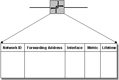
Figure 4 Router routing process. Routing TablesDuring the routing process, the routing decisions of hosts and routers are aided by a database of routes known as the routing table. The routing table is not exclusive to a router. Depending on the routable protocol, hosts may also have a routing table that may be used to decide the best router for the packet to be forwarded. IP hosts have a routing table. IPX hosts do not have a routing table. The types of possible entries in a routing table include: · &nb 12412c216m sp; &nb 12412c216m sp; Network Route. A route to a specific Network ID in the internetwork. · &nb 12412c216m sp; &nb 12412c216m sp; Host Route. A route to a specific internetwork address (Network ID and Host ID). Instead of making a routing decision based on just the network ID, the routing decision is based on the combination of network ID and host ID. Host routes allow intelligent routing decisions to be made for each internetwork address. Host routes are typically used to create custom routes to control or optimize specific types of internetwork traffic. · &nb 12412c216m sp; &nb 12412c216m sp; Default Route. A route that is used when no other routes for the destination are found in the routing table. For example, if a router or host cannot find a network route or host route for the destination, the default route is used. Rather than being configured with routes for all the Network IDs in the internetwork, the default route is used to simplify the configuration of end systems or routers. Routing Table StructureAs illustrated in Figure 5, entries in the routing table usually consist of the following fields: Network IDThe Network ID field contains the network address for a network route or an internetwork address for a host route. Forwarding AddressThe forwarding address field contains the address to which the packet is to be forwarded. The forwarding address can be a physical address or an internetwork address. For network IDs to which the end system or router is directly attached, the Forwarding Address field may be blank. InterfaceThe interface field indicates the network interface that will be used when forwarding packets to the Network ID. This is a port number or other type of logical identifier. For example, the interface for a 3-COM Etherlink III network interface card may be referred to as ELNK3 in the routing table. MetricThe metric field indicates the preference for a route. If multiple routes exist to a given network ID, the metric is used to decide which route is to be taken. The metric is an indication of the cost of the route, therefore the lowest metric is the preferred route. Some routing algorithms only store a single route to any Network ID in the routing table even when multiple routes exist. In this case, the metric is used by the router to decide which route to store in the routing table. Metrics can indicate different ways of expressing a route preference: · &nb 12412c216m sp; &nb 12412c216m sp; Hop Count. A common metric. Indicates the number of routers (hops) in the path to the network ID. · &nb 12412c216m sp; &nb 12412c216m sp; Delay. A measure of time that is required for the packet to reach the network ID. Delay is used to indicate the speed of the path (LAN links have a low delay, WAN links have a high delay) or a congested condition of a path. · &nb 12412c216m sp; &nb 12412c216m sp; Throughput. The effective amount of data that can be sent along the path per second. Throughput is not necessarily a reflection of the bit rate of the link, as a very busy Ethernet link may have a lower throughput than an unutilized 64-Kbps WAN link. · &nb 12412c216m sp; &nb 12412c216m sp; Reliability. A measure of the path constancy. Some types of links are more prone to link failures than others. For example, with WAN links, leased lines are more reliable than dial-up lines. LifetimeThe lifetime field indicates the lifetime that the route is considered valid. When routes are learned through the exchange of information with other routers, this is an additional field that is used. Learned routes have a finite lifetime. To keep a learned route in the routing table, the route must be refreshed through a periodic process. If a learned route's lifetime expires, it is removed from the routing table. The timing out of learned routes provides a way for routers to reconfigure themselves when the topology of an internetwork changes due to a downed link or a downed router. The lifetime field is typically not visible in routing tables.
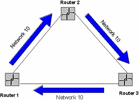
Figure 5 Routing table structure This list of fields is a representative list in the routing tables. Actual fields in the routing tables for different routable protocols may vary. For information on the IP routing table, see the "Introduction to TCP/IP" whitepaper. Locality of the Routing TableAll the routing decisions made by the end system or the router are based on information in a local routing table that physically resides on the system making the routing decision. There is no single, holistic view of the internetwork that is being gathered by a server and downloaded to each end system and router so that all users have the same view of the internetwork and all traffic flows along predictable pathways. Each router in a path between a source and destination makes a local routing decision based on its local routing table. The path taken from the source to the destination may not be the same as the path for response packets from the destination back to the source. If the information in the local routing tables of the end systems or routers is incorrect due to misconfiguration or changing network conditions, then routing problems can result. Troubleshooting routing problems may involve the analysis of the routing tables of the end systems (source and destination) and all the routers forwarding packets between them. Static and Dynamic RoutersFor routing between routers to work efficiently in an internetwork, routers must have knowledge of other network IDs or be configured with a default route. On large internetworks, the routing tables must be maintained so that the traffic always travels along optimal paths. How the routing tables are maintained defines the distinction between static and dynamic routing: Static RoutingA router with manually configured routing tables is known as a static router. A network administrator, with knowledge of the internetwork topology, manually builds and updates the routing table, programming all routes in the routing table. Static routers can work well for small internetworks but do not scale well to large or dynamically changing internetworks due to their manual administration. Static routers are not fault tolerant. The lifetime of a manually configured static route is infinite and, therefore, static routers do not sense and recover from downed routers or downed links. A good example of a static router is a multihomed computer (a computer with multiple network interface cards) running Windows NT. Creating a static IP router with Windows NT is as simple as installing multiple network interface cards, configuring TCP/IP, and enabling IP routing. Dynamic RoutingA router with dynamically configured routing tables is known as a dynamic router. Dynamic routing consists of routing tables that are built and maintained automatically through an ongoing communication between routers. This communication is facilitated by a routing protocol, a series of periodic or on-demand messages containing routing information that is exchanged between routers. Except for their initial configuration, dynamic routers require little ongoing maintenance and, therefore, can scale to larger internetworks. Dynamic routing is fault tolerant. Dynamic routes learned from other routers have a finite lifetime. If a router or link goes down, the routers sense the change in the internetwork topology through the expiration of the lifetime of the learned route in the routing table. This change can then be propagated to other routers so that all the routers on the internetwork become aware of the new internetwork topology. The ability to scale and recover from internetwork faults makes dynamic routing the better choice for medium, large, and very large internetworks. A good example of a dynamic router is a computer with Windows NT Server version 4.0 and the Routing and Remote Access Service running the Routing Information Protocol (RIP) and Open Shortest Path First (OSPF) routing protocols for IP and RIP for IPX. Routing ProblemsRouting problems can occur when either the host or router's routing tables contains information that does not reflect the correct topology of the internetwork. Routing LoopsDuring the router routing process, the packet will be forwarded in the optimal direction according to the information in the local routing table. If the routing table entries on all the routers are correct, the packet takes the optimal path from the source to the destination. However, if any routing table entries are not correct, either though a misconfiguration or through learned routes that do not accurately reflect the topology of the internetwork, then routing loops can form. A routing loop is a path through the internetwork for a network ID that loops back onto itself. Figure 6 illustrates a routing loop in which: · &nb 12412c216m sp; &nb 12412c216m sp; According to the routing table on Router 1, the optimal route to Network 10 is through Router 2. · &nb 12412c216m sp; &nb 12412c216m sp; According to the routing table on Router 2, the optimal route to Network 10 is through Router 3. · &nb 12412c216m sp; &nb 12412c216m sp; According to the routing table on Router 3, the optimal route to Network 10 is through Router 1. The hop count in the network layer header is used to prevent the packet from perpetually looping. Each time a router passes the packet from one network to another, it either increases or decreases the hop count. If the hop count reaches its maximum value (when increasing) or is 0 (when decreasing), the packet is discarded by the router. For example, IPX hosts send IPX packets with a 0 hop count. Each RIP for IPX router increases the hop count by one. When it reaches 16, packet is discarded without notifying the sending host. This is known as a silent discard. When IP hosts send IP packets, they set a maximum hop count in the Time-to-Live (TTL) field in the IP header. Each IP router encountered decreases the TTL by one. When the TTL is 0, the IP router discards the packet and sends an ICMP Time Exceeded message back to the sending host. By default, Windows NT 4.0 TCP/IP hosts set the TTL to 128.
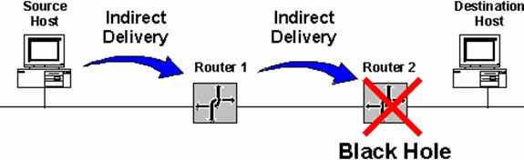
Figure 6 An example of a routing loop. Black HolesCommon internetworking protocols such as IP and IPX are connectionless, datagram-based protocols. They do not guarantee a successful delivery. IP and IPX attempt a best effort, unacknowledged delivery to the next hop or the final destination. This behavior can lead to conditions on the internetwork in which data is lost. If a downstream router goes down and its absence is not detected by the upstream router, the upstream router will still forward the packets to the downed router. Because the failed downstream router does not receive them, the packets forwarded by the upstream router are dropped from the internetwork. The upstream router is sending packets to a black hole, an area of the internetwork in which packets are lost. In Figure 7, Router 1 has not been informed that Router 2 has failed and continues to forward packets to Router 2. The failed Router 2 is a black hole.
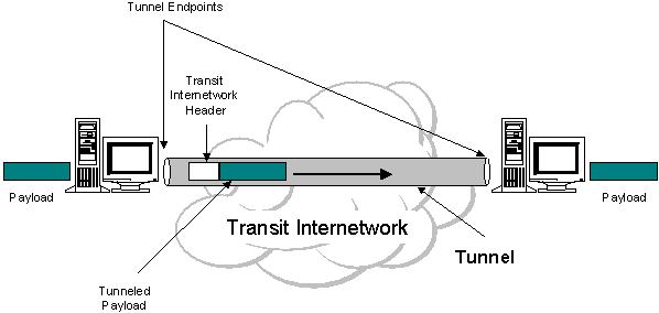
Figure 7 A routing black hole. Black holes form when a link or router fails, and the failure is not yet detected. In a static routing environment, black holes persist until the link or router is brought back up or the static routers are reconfigured by the network administrator. In a dynamic routing environment, routers sense downed links or routers through the expiration of the lifetime of learned routes in their routing tables. Note This section discusses routing black holes in terms of a downed router or a downed link. Black holes can also be created when routers silently discard packets. An example is a black hole Path Maximum Transmit Unit (PMTU) IP router that silently discards IP packets that need to be fragmented when the Don't Fragment bit in the IP header is set. Routers and Broadcast TrafficInternetwork-level broadcasts are MAC-level broadcast frames with a special destination internetwork address that informs the router that the packet is to be forwarded to all other networks except the network on which it was received. A MAC-level broadcast frame is used to reach all the hosts on a network. Routers, unlike bridges, do not forward MAC-level broadcast traffic. However, to reach all the hosts on an internetwork, some routable protocols support the use of internetwork-level broadcasts. Routers must be configured to pass internetwork-level broadcast traffic. The inherent danger of forwarding internetwork-level broadcasts is the possibility of an internetwork-level broadcast storm in which a host malfunctions and continuously sends out the same internetwork-level broadcast packet. If the routers forward this traffic, the result is that all the hosts on the internetwork process each broadcast frame, possibly crippling the entire internetwork. An example of an internetwork-level broadcast is the Network Basic Input-Output System (NetBIOS) over IPX broadcast. NetBIOS applications on an IPX internetwork use a NetBIOS over IPX broadcast to perform name registration, resolution, and release. When the NetBIOS over IPX broadcast packet is received by an IPX router, the router records the network on which the packet was received in the NetBIOS over IPX header. Thus, the internetwork path is recorded in the NetBIOS over IPX header as it traverses the IPX internetwork. Before being forwarded, the IPX router checks the internetwork path information in the NetBIOS over IPX header to prevent the forwarding of the NetBIOS over IPX broadcast onto a network on which it has already traveled. This prevents the broadcast from looping and causing more broadcast traffic. As an additional safeguard, NetBIOS over IPX broadcast packets can only propagate across eight networks using seven routers. At the eighth router, the packet is silently discarded. Note An IPX internetwork path is recorded in a similar fashion to the MAC-sublayer routing information in a Token Ring source routing Explorer frame. However, unlike Token Ring source routing, the IPX internetwork path is not used in the subsequent communication. The IPX internetwork path is only used to prevent the broadcast packet from being forwarded on the same IPX network more than once. TunnelingTunneling, also known as encapsulation, is a method of using an internetwork infrastructure of one protocol to transfer a payload, the frames (or packets) of another protocol (see Figure 8). Instead of sending the frame as it is produced by the originating host, the frame is encapsulated with an additional header. The additional header provides routing information so the encapsulated payload can traverse an intermediate internetwork (also known as a transit internetwork). The encapsulated packets are then routed between tunnel endpoints over the transit internetwork. Once the encapsulated payload packets reach their destination on the transit internetwork, the frame is de-encapsulated and forwarded to its final destination. The entire process of encapsulation, transmission, and de-encapsulation of packets is tunneling. The logical path through which the encapsulated packets travel through the transit internetwork is called a tunnel.
Figure 8 Tunneling. The transit internetwork can be any internetwork. The Internet is a good example as the most widely known public internetwork. There are also many examples of tunnels that are carried over corporate internetworks. Some common types of tunneling: · &nb 12412c216m sp; &nb 12412c216m sp; SNA Tunneling over IP Internetworks. To send System Network Architecture (SNA) traffic across a corporate IP internetwork, the SNA frame is encapsulated with a User Datagram Protocol (UDP) and IP header. This is known as Data Link Switching (DLSw) and is described in RFC 1434. · &nb 12412c216m sp; &nb 12412c216m sp; IP Tunneling for Novell NetWare. IPX packets are sent to a NetWare server or IPX router that wraps the IPX packet with a UDP and IP header and sends them across an IP internetwork. The destination IP router removes the UDP and IP header and forwards them to the appropriate IPX destination. · &nb 12412c216m sp; &nb 12412c216m sp; Point to Point Tunneling Protocol (PPTP). PPTP allows IP, IPX, or NetBIOS Extended User Interface (NetBEUI) traffic to be encrypted and encapsulated in an IP header to be sent across a corporate IP internetwork or public internetworks like the Internet. · &nb 12412c216m sp; &nb 12412c216m sp; Layer 2 Tunneling Protocol (L2TP). L2TP allows IP, IPX, or NetBEUI traffic to be encrypted and then sent over any medium that supports point-to-point datagram delivery such as IP, X.25, Frame Relay, or ATM. · &nb 12412c216m sp; &nb 12412c216m sp; IP Security (IPSec) Encapsulating Security Payload (ESP) Tunnel Mode. IPSec Encapsulating Security Payload (ESP) Tunnel Mode allows IP datagrams to be encrypted and then encapsulated in an IP header to be sent across a corporate IP internetwork or public internetworks like the Internet. Note Windows NT Server version 4.0 only ships with support for the PPTP tunneling discussed above. Microsoft SNA Server provides support for the SNA tunneling described above. Foundations of Routing ProtocolsDynamic routers use routing protocols to facilitate the ongoing communication and dynamic updating of routing tables. Routing protocols represent additional network traffic overhead on the network. This additional traffic can become an important factor in planning WAN link usage. Examples of routing protocols include such protocols as RIP (Routing Information Protocol) and OSPF (Open Shortest Path First) for IP, RIP (Routing Information Protocol) and NLSP (NetWare Link Services Protocol) for IPX. In some cases, such as RIP for IP (version 1) and RIP for IPX, the routing information is exchanged using MAC-level broadcasts. An important element of a routing protocol implementation is its ability to sense and recover from internetwork faults. How quickly it can recover is determined by the type of fault, how it is sensed, and how the routing information is propagated through the internetwork. When all the routers on the internetwork have the correct routing information in their routing tables, the internetwork has converged. When convergence is achieved, the internetwork is in a stable state and all routing occurs along optimal paths. When a link or router fails, the internetwork must reconfigure itself to reflect the new topology. Information in routing tables must be updated. Until the internetwork reconverges, it is in an unstable state in which routing loops and black holes can occur. The time it takes for the internetwork to reconverge is known as the convergence time. The convergence time varies based on the routing protocol and the type of failure (downed link or downed router). Non-Internet backbone routing protocols are based either on a distance vector or link state technology. The main differences between distance vector and link state routing protocols are in: · &nb 12412c216m sp; &nb 12412c216m sp; What routing information is exchanged · &nb 12412c216m sp; &nb 12412c216m sp; How the information is exchanged · &nb 12412c216m sp; &nb 12412c216m sp; How quickly the internetwork can recover from a downed link or a downed router Distance VectorRouters use distance vector-based routing protocols to periodically advertise the routes in their routing tables. The periodic advertisement contains a hop count (the distance) and a direction in which the route is located (the vector). Routing information exchanged between typical distance vector-based routers is unsynchronized and unacknowledged. Table 1 lists some distance vector-based routing protocols: Table 1 Examples of Distance Vector-based Routing Protocols
Windows NT Server version 4.0 provides the provides the RIP (version 1) for IP, RIP for IPX, and RTMP for AppleTalk routing protocols. Windows NT Server version 4.0 with the Routing and Remote Access Service provides the RIP (version 2) for IP routing protocol. Advantages of distance vector-based routing protocols: · &nb 12412c216m sp; &nb 12412c216m sp; Simpler. Distance vector-based routing protocols are simple router advertisement processes that are easy to understand. · &nb 12412c216m sp; &nb 12412c216m sp; Easy to configure. In its simplest incarnation, configuring a distance vector-based routing protocol is as easy as enabling it on the router interfaces. Disadvantages of distance vector-based routing protocols: · &nb 12412c216m sp; &nb 12412c216m sp; Large routing tables. Multiple routes to a given network ID can be reflected as multiple entries in the routing table. In a large internetwork with multiple paths, the routing table can have hundreds or thousands of entries. · &nb 12412c216m sp; &nb 12412c216m sp; High network traffic overhead. Route advertising is done periodically even after the internetwork has converged. · &nb 12412c216m sp; &nb 12412c216m sp; Does not scale. Between the size of the routing table and the high overhead, distance vector-based routing protocols do not scale well to large and very large internetworks. · &nb 12412c216m sp; &nb 12412c216m sp; High convergence time. Due to the unsynchronized and unacknowledged way that distance vector information is exchanged, convergence of the internetwork can take several minutes. While converging, routing loops and black holes can occur. Link StateRouters using link state-based routing protocols exchange link state advertisements (LSAs) which consist of a router's attached network IDs and interface costs. LSAs are advertised upon startup and when changes in the internetwork topology are sensed. LSAs are sent using directed or multicast traffic rather than broadcasting. Link state routers build a database of LSAs and use the database to calculate optimal routes which are added to the routing table. Routing information exchanged between link state-based routers is synchronized and acknowledged. Table 2 lists some link-state routing protocols: Table 2 Examples of Link State-based Routing Protocols
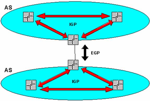
Windows NT Server version 4.0 with the Routing and Remote Access Service provides the OSPF for IP routing protocol. Advantages of link state routing protocols: · &nb 12412c216m sp; &nb 12412c216m sp; Smaller routing tables. Only a single optimal route for each network ID is stored in the routing table. · &nb 12412c216m sp; &nb 12412c216m sp; Low network overhead. Link state-based routers do not exchange any routing information when the internetwork has converged. · &nb 12412c216m sp; &nb 12412c216m sp; Ability to scale. Between the smaller routing tables and low overhead, link state-based routing protocols scale well to large and very large internetworks. · &nb 12412c216m sp; &nb 12412c216m sp; Lower convergence time. Link state-based routing protocols have a much lower convergence time and the internetwork is converged without routing loops. Disadvantages of link state routing protocols: · &nb 12412c216m sp; &nb 12412c216m sp; Complex. Link state-based routing protocols are much more complex and difficult to understand and troubleshoot than distance vector-based routing protocols. · &nb 12412c216m sp; &nb 12412c216m sp; More difficult to configure. A link state-based routing protocol implementation requires additional planning and configuration. Routing InfrastructureThe routing infrastructure is the entire structure of the routed internetwork. The infrastructure has important attributes to consider when you are deciding on which routable protocols and routing protocols to use. Single-path vs. Multi-pathIn a single-path routing infrastructure, only a single path exists between any two networks in the internetwork. While this may simplify the routing tables and the packet flow paths, single-path internetworks are not fault tolerant. A fault can be sensed with a dynamic router, but the networks across the failure are unreachable for the duration of the fault. A downed link or a downed router must be brought back up before packets can be delivered successfully across the downed link or router. In a multi-path routing infrastructure, multiple paths exist between networks in the internetwork. Multi-path internetworks are fault tolerant when dynamic routing is used, and some routing protocols, such as OSPF, can balance the load of network traffic across multiple paths with the same metric value. Multi-path internetworks, however, can be more complex to configure and can have a higher probability of routing loops during convergence when using distance vector-based routing protocols. Flat vs. HierarchicalIn a flat routing infrastructure, each network ID is represented individually in the routing table. The network IDs have no network/subnetwork structure and cannot be summarized. RIP-based IPX internetworks use flat network addressing and have a flat routing infrastructure. In a hierarchical routing infrastructure, groups of network IDs can be represented as a single routing table entry through route summarization. The network IDs in a hierarchical internetwork have a network/subnetwork/sub-subnetwork structure. A routing table entry for the highest level (the network) is also the route used for the subnetworks and sub-subnetworks of the network. Hierarchical routing infrastructures simplify routing tables and lower the amount of routing information that is exchanged, but they require more planning. IP implements hierarchical network addressing, and IP internetworks can have a hierarchical routing structure. In hierarchical routing infrastructures, the internetwork can be divided into routing domains (also known as regions or areas). A routing domain is a collection of contiguous networks connected by routers that share the routing information for the routes within the domain. Routing domains are connected by a common routing domain called the backbone. Intra-domain routing is performed by the routers within the domain. Inter-domain routing is performed by domain routers connected to the backbone. Autonomous SystemsIn very large internetworks, it is necessary to divide the internetwork into separate entities known as autonomous systems. An autonomous system (AS) is a portion of the internetwork under the same administrative authority. The administrative authority can be an institution or corporation but can also be defined by the use of a routing protocol such as OSPF. The contiguous portion of an IP internetwork that is using OSPF to distribute routing information is under OSPF administrative authority and is, therefore, an OSPF AS. The AS may be further divided into domains, regions, or areas that define a hierarchy within the AS.
Figure 9 Autonomous systems, interior gateway protocols, and exterior gateway protocols . The protocols used to distribute routing information within an AS are known as Interior Gateway Protocols (IGPs). The protocols used to distribute routing information between ASs are known as Exterior Gateway Protocols (EGPs). Interior Gateway Protocols (IGPs)IGPs are intra-AS routing protocols. IGPs distribute routes within the AS in either a flat or hierarchical manner. Examples of IGPs for IP internetworks are: · &nb 12412c216m sp; &nb 12412c216m sp; RIP for IP. An RFC-based distance vector IGP. · &nb 12412c216m sp; &nb 12412c216m sp; OSPF. An RFC-based link state IGP. · &nb 12412c216m sp; &nb 12412c216m sp; Interior Gateway Routing Protocol (IGRP). A distance vector IGP developed by Cisco Systems, Inc. Windows NT Server version 4.0 with the Routing and Remote Access Service provides the RIP for IP and OSPF routing protocols. Exterior Gateway Protocols (EGPs)EGPs are inter-AS routing protocols. EGPs define the way that all of the networks within the AS are advertised outside of the AS. This can include a list of network routes in a flat routing infrastructure or a list of summarized network routes in a hierarchical routing infrastructure. EGPs are independent of the IGPs used within the AS. EGPs can facilitate the exchange of routes between ASs that use different IGPs. Examples of EGPs for IP internetworks are: · &nb 12412c216m sp; &nb 12412c216m sp; Exterior Gateway Protocol (EGP). An RFC-based EGP that was developed for use between ASs on the Internet. EGP is no longer used on the Internet due to its lack of support for complex, multi-path environments and Classless Inter-Domain Routing (CIDR). · &nb 12412c216m sp; &nb 12412c216m sp; Border Gateway Protocol (BGP). An RFC-based EGP that is currently used between ASs on the Internet. BGP overcomes the weaknesses of EGP. The current version of BGP being used on Internet backbone routers is BGP4. Windows NT Server version 4.0 with the Routing and Remote Access Service does not provide the EGP and BGP routing protocols. For More InformationFor the latest information on Windows NT Server, check out Microsoft TechNet or our World Wide Web site at https://www.microsoft.com/ntserver the Windows NT Server Forum on the Microsoft Network (GO WORD: MSNTS). For more information on using Windows NT Server as a networking and communications platform, check out https://www.microsoft.com/communications/ . To download the Routing and Remote Access Service, check out https://www.microsoft.com/communications/routing&ras.htm . © 1998 Microsoft Corporation. All rights reserved. The information contained in this document represents the current view of Microsoft Corporation on the issues discussed as of the date of publication. Because Microsoft must respond to changing market conditions, it should not be interpreted to be a commitment on the part of Microsoft, and Microsoft cannot guarantee the accuracy of any information presented after the date of publication. This White Paper is for informational purposes only. MICROSOFT MAKES NO WARRANTIES, EXPRESS OR IMPLIED, IN THIS DOCUMENT. The BackOffice logo, Microsoft, Windows, and Windows NT are registered trademarks of Microsoft Corporation. Other product or company names mentioned herein may be the trademarks of their respective owners. Microsoft Corporation . One Microsoft Way . Redmond, WA 98052-6399 . USA 0X97 Part no. 098-XXXXX |
|
