ALTE DOCUMENTE
|
||||||||||
|
|
|
|
|
|
|
a |
|
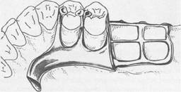
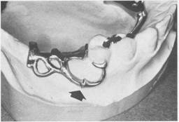
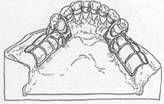
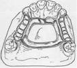
Fig. 5-34 Maxillary Class I partial denture framework with anatomic replica palatal major connector. Although retention is increased by using broad major connector, need for indirect retainers still exists, and they are placed on mesio-occlusal surfaces of first premolars. Direct retention is furnished by bar-type clasps engaging distobuccal undercuts on second premolars. Metal extension from framework contacts prepared guiding planes on distal surfaces of second premolars to complete clasp assembly. |
|
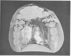
The palatal plate may be used in anyone of three ways. It may be used as a plate of varying width that covers the area between two or more edentulous areas (Fig. 5-34), as a complete or partial cast plate that extends posteriorly to the junction of the hard and soft palates (Figs. 5-35 and 5-36) or in the form of an anterior palatal connector with a provision for extending an acrylic resin denture base posteriorly (Fig. 5-37). The palatal plate should be located anterior to the posterior palatal seal area. Little posterior seal is ever necessary with a metal palate because of the accuracy and stability of the cast metal. This is in contrast to the posterior palatal seal needed with acrylic resin complete denture bases. When the last remaining abutment tooth on either side of a Class I arch is the canine or first premolar tooth, complete palatal coverage is strongly advised, especially when the residual ridges have undergone excessive vertical resorption. This may be accomplished in One of two ways. One method is to use a complete cast plate that |
|
Chapter 5 |
|
Major and minor connectors |
|
|
|
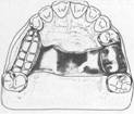
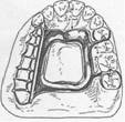
Fig. 5-35 Anatomic replica palatal major connector for a Class II, modification 1, partial denture. Anterior border avoids coverage of anterior rugae; posterior border lies well back on immovable hard palate, crossing midline at a right angle. Total contact provides excellent auxiliary retention without objectionable bulk. |
|
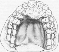
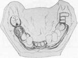
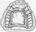
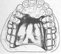
Fig. 5-36 Complete coverage palatal major connector. Posterior border terminates at junction of hard and soft palates. Anterior portion, in the form of palatal linguoplate, is supported by positive lingual rest seats on canines. Location of finishing lines is most important in this type of major connector. Anteroposteriorly, they should be parallel to a line along the center of the ridge crest and located just lingual to an imaginary line contacting lingual surfaces of missing natural teeth. Alteration of natural palatal contour should be anticipated with its attendant detrimental effect on speech if these contours are not followed. |
|
|
|
|
|
|
|
McCracken's removable partial prosthodontics |
|
A |
|
B |
|
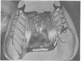
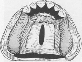
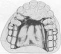
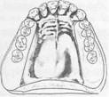
Fig. 5-37 A, Maxillary major connector in the form of palatal linguoplate with provision for attaching fullcoverage acrylic resin denture base. B, Completed removable partial denture with acrylic resin base. Palatal linguoplate is supported by rests occupying lingual rest seats prepared in cast restorations on canines. This type of removable partial denture is particularly applicable where (1) residual ridges have undergone extreme vertical resorption and (2) terminal abutments have suffered some bone loss and splinting cannot be accomplished. |
|
extends to the junction of the hard and soft palates (see Fig. 5-36). The other method is to use a cast major connector anteriorly, with retention posteriorly, for the attachment of a resin denture base that extends posteriorly to the anatomic landmarks previously described (see Fig. 5-37). The several advantages of a cast palate over a |
|
complete resin palate make the complete cast palate sufficiently preferable to offset the slight additional cost. However, when the cost and fee must be held to a minimum, the latter method may be used satisfactorily. The partial metal palate may also be used when later relining is anticipated. In such circumstances the posterior beading can be redone as part of the relining procedure. The complete palatal plate is not a connector that has received universal use. It has, however, become accepted as a satisfactory palatal connector for many maxillary partial dentures. In all circumstances the portion contacting the teeth must have positive support from adequate rest seats. The dentist should be familiar with its use and, at the same time, with its limitations so that it may be used intelligently and to the fullest advantage. |
|
Design of maxillary major connectors In 1953 Blatterfein described a systematic approach to designing maxillary major connectors. His method involves five basic steps and is certainly applicable to most maxillary removable partial denture situations. Using a diagnostic cast and knowledge of the relative displaceability of the palatal tissues, including those covering the median palatal raphe, he recommends the following basic steps: |
|
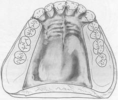
Step 1: Outline of primary bearing areas. The primary bearing areas are those that will be covered by the denture base(s) (Fig. 5-38, A and B). Step 2: Outline of nonbearing areas. The nonbearing areas are the lingual gingival tissues within 5 to 6 mm of the remaining teeth, hard areas of the medial palatal raphe (induding tori), and palatal tissues posterior to the vibrating line (Fig. 5-38, C). Step 3: Outline of connector areas. Steps 1 and 2, when completed, provide an outline or designate areas that are available to place components of major connectors (Fig. 5-38, C). Step 4: Selection of connector type. Selection of the type of connector(s) is based on four factors: mouth comfort, rigidity, location of |
|
|
|
|
|
|
|
|
|
A |
|
c |
|
Chapter 5 |
|
Major and minor connectors |
|
|
|
B |
|
D |
|
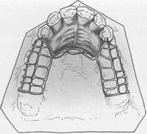
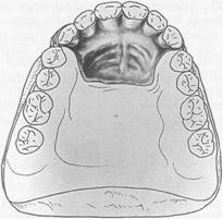
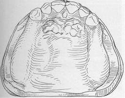
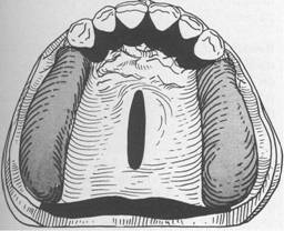
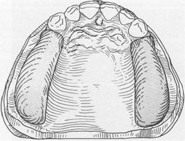
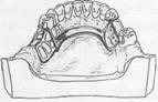
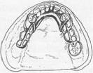
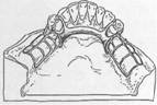
Fig. 5-38 A, Diagnostic cast of partially edentulous maxillary arch. B, Denture base areas are outlined. C, Nonbearing areas outlined in black, which include lingual soft tissue within 5 to 6 mm of teeth, an unyielding median palatal raphe area, and soft palate. The space bounded by bearing and nonbearing area outlines is available for placement of major connector. D, Major connector selected will be rigid and noninterfering with tongue and will cover a minimum of the palate. |
|
denture bases, and indirect retention. Connectors should be of minimum bulk and should be positioned so that interference with the tongue during speech and mastication is not encountered. Connectors must have a maximum of rigidity to distribute stress bilaterally. The double-strap type of major connector provides the maximum rigidity without bulk and total tissue coverage. In many instances the choice of a strap type of major connector is limited by the location of the edentulous ridge areas. When edentulous areas are located |
|
anteriorly, the use of only a posterior strap is not recommended. By the same token, when only posterior edentulous areas are present, the use of only an anterior strap is not recommended. The need for indirect retention influences the outline of the major connector. Provision must be made in the major connector so that indirect retainers may be attached. Step 5: Unification. After selection of the type of major connector based on the considerations in Step 4, the denture base areas and connectors are joined (Fig. 5-38, D). |
|
|
|
|
|
|
|
McCracken's removable partial prosthodontics |
|
A |
|
B |
|
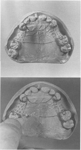
Fig. 5-39 A, Framework design on master cast before preparation for duplication in refractory investment. Shallow groove (0.5 mm) has been scribed on outline of anterior and posterior borders of major connector. Anterior outline follows valleys of rugae. Design calls for cast bases. B, Beading is readily accomplished with cleoid carver. Slightly rounded groove is preferred to V-shaped groove. |
|
The indications for the use of complete palatal coverage have been previously discussed in this chapter. Although there are many variations in palatal major connectors, a thorough comprehension of all factors influencing their |
|
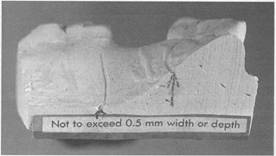
Fig. 5-40 Sagittal view of sectioned cast with width and depth of beading indicated. |
|
design will lead to the best design for each patient. |
|
Beading of the maxillary cast. Beading is a term used to denote the scribing of a shallow groove on the maxillary master cast outlining the palatal major connector exclusive of rugae areas (Fig. 5-39, A and B). The purposes of beading are as follows: 1. To transfer the major connector design to the investment cast (Fig. 5-41, A) 2. To provide a visible finishing line for the casting (Fig. 5-41) 3. To ensure intimate tissue contact of the major 20520o1414u connector with selected palatal tissues Beading is readily accomplished by using an appropriate instrument, such as a cleoid carver. Care must be exercised to create a groove not in excess of 0.5 mm in width or depth (Figs. 5-40 and 5-42, A and B). |
|
MINOR CONNECTORS |
|
Minor connectors are those components that serve as the connecting link between the major connector or base of a removable partial denture and the other components of the prosthesis, such as the clasp assembly, indirect retainers, occlusal rests, or cingulum rests. In many instances a minor connector may be continuous with some other part of the denture. For example, an occlusal rest at one end of a linguoplate is actually the terminus of a minor connector, even though that minor connector is |
|
|
|
|
|
A |
|
B |
|
Fig. 5-41 A, Refractory cast. Note definitive outline of major connector transferred in duplicating master cast. Wax pattern for major connector can be accurately executed by beading. H, Finished casting is returned to master cast. Major connector is confined to previously scribed beading. |
|
continuous with the linguoplate. Similarly, the portion of a denture base frame that supports the clasp and the occlusal rest is a minor connector, joining the major connector with the clasp proper. Those portions of a denture framework by which the denture bases are attached are minor connectors. |
|
Functions In addition to joining denture parts, the minor connector serves two other purposes that are diametrically opposed in function. 1. To transfer functional stress to the abutment teeth. Occlusal forces applied to the artificial teeth are transmitted through the base to the |
|
Chapter 5 |
|
Major and minor connectors |
|
|
|
A |
|
B |
|
Fig. 5-42 A, Tissue side of casting. Note slightly elevated ridges outlining major connector. H, Casting finished to demarcated outline. |
|
underlying ridge tissues if that base is primarily tissue supported. Occlusal forces applied to the artificial teeth are also transferred to abutment teeth through occlusal rests. The minor connectors arising from a rigid major connector make possible this transfer of functional stress throughout the dental arch. This, then, is a prosthesis-toabutment function of the minor connector. 2. To transfer the effect of the retainers, rests, and stabilizing components to the rest of the denture. This is an abutment-to-prosthesis function of the minor connector. The effect of occlusal rests on supporting tooth surfaces, the action of retainers, the effect of stabilizing (reciprocal) clasp arms, the effect of minor connectors, contacting guiding planes, and other stabilizing components are transferred to the remainder of the denture by the minor |
|
|
|
|
|
|
|
McCracken's removable partial prosthodontics |
|
Fig. 5-43 The proposed minor connector variation for a maxillary molar. |
|
connectors and then are transferred throughout the dental arch. T_us forces applied on one portion of the denture may be resisted by other components placed elsewhere in the arch for that purpose. A stabilizing component on one side of the arch may be placed to resist horizontal forces originating on the opposite side. This is possible only because of the transferring effect of the minor connector, which supports that stabilizing component, and the rigidity of the major connector. |
|
Form and location Like the major connector, the minor connector must have sufficient bulk to be rigid; otherwise the transfer of functional stresses to the supporting teeth and tissues will not be effective. At the same time, the bulk of the minor connector must be as unobjectionable as possible. A minor connector contacting the axial surface of an abutment should not be located on a convex surface; instead it should be located in an embrasure where it will be least noticeable to the tongue. It should conform to the interdental embrasure, passing vertically from the major connector so that the gingival crossing is abrupt and covers as little of the gingival tissues as possible. It should be thickest toward the lingual surface tapering toward the contact area. The deepest part of the interdental embrasure should |
|
Fig. 5-44 Undercuts in lingual embrasure between premolars have been blocked out parallel to path of placement. Minor connector is V shaped to avoid bulk, with greatest depth of the V being at junction with occlusal rests. A, Demonstrates taper to tooth surface to accommodate tongue. |
|
have been blocked out to avoid interference during placement and removal and to avoid any wedging effect on the teeth contacted. A modification of the conventional removable partial denture minor connector has been proposed by Radford. He limits the application of this variation in minor connector design to the maxillary arch only. He suggests placing the minor connector in the center of the lingual surface of the maxillary abutment tooth (Fig. 5-43). He rationalizes that this reduces the amount of gingival tissue coverage and provides enhanced guidance for the partial denture during insertion and removal as well as increased stabilization against horizontal and rotational forces. The proposed variation could encroach on the tongue space and provide more obvious borders and a greater potential space between the connector and the abutment for food entrapment. The proposed variation, if used with thoughtful design for form and function, could be an acceptable alternative. When a minor connector contacts tooth surfaces on either side of the embrasure in which it lies, it should be tapered to the teeth so that the tongue encounters a smooth surface (Fig. 5-44). Sharp angles should be avoided, and |
|
|
|
|
|
t I i |
|
Fig.5-45 Minor connectors (arrows) contacting guiding plane surface are as broad as about one half of the distance between tips of adjacent buccal and lingual cusps of the abutment tooth. They extend gingivally, contacting an area of the abutment from the marginal ridge to two thirds the length .9f the enamel crown. Viewed from above, they are triangular; the apex of the triangle being buccally located and the base of the triangle being located lingually. Less interference with arrangement of adjacent artificial tooth is encountered with minor connectors so shaped. |
|
|
|
spaces should not exist for the trapping of food debris. It is a minor connector that contacts the guiding plane surfaces of the abutment teeth, whether as a connected part of a direct retainer assembly or as a separate entity (Fig. 5-45). Here the minor connector must be wide enough to use the guiding plane to the fullest advantage. When it gives rise to a clasp arm, the connector should be tapered to the tooth below the origin of the clasp. If no clasp arm is formed (as when a bar clasp arm originates elsewhere), the connector should be tapered to a knife-edge the full length of its buccal aspect. When an artificial tooth will be placed against a proximal minor connector, the minor connector's greatest bulk should be toward the lingual aspect of the abutment tooth. This way sufficient bulk is ensured with the least interference to placement of the artificial tooth. Ideally the artificial tooth should contact the abutment |
|
Chapter 5 |
|
Major and minor connectors |
|
|
|
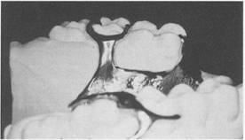
Fig. 5-46 Finishing line at junction of ladderlike minor connector and major connector blends smoothly into minor connector contacting distal guiding plane on second premolar. Framework is feathered toward tissue anterior to finishing line to avoid as much bulk in this area as possible without compromising the strength of the butt-type joint. |
|
tooth with only a thin layer of metal intervening buccally. Lingually the bulk of the minor connector should lie in the interdental embrasure, the same as between two natural teeth. As stated previously, those portions of a denture framework by which acrylic resin denture bases are attached are minor connectors. This type of minor connector should be so designed that it will be completely embedded within the denture base. The junctions of these mandibular minor connectors with the major connectors should be strong butt-type joints but without appreciable bulk (Fig. 5-46). Angles formed at the junctions of the connectors should not be greater than 90 degrees, thus ensuring the most advantageous and strongest mechanical connection between the acrylic resin denture base and the major connector. An open latticework or ladder type of design is preferable and is conveniently made by using preformed I2-gauge half-round and I8-gauge round wax strips. The minor connector for the mandibular distal extension base should extend posteriorly about two thirds the length of the |
|
|
|
|
|
|
|
|
|
McCracken's removable partial prosthodontics |
|
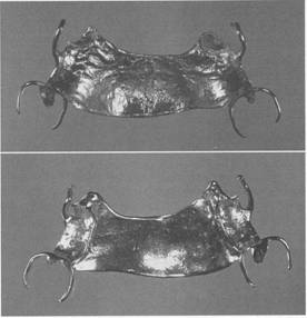
Fig. 5-47 Wax pattern for minor connector by which acrylic resin denture base will be attached. It is extended on both lingual and buccal surfaces of residual ridge (arrow) and is made by using I2-gauge half-round forms and IS-gauge round forms. Note that this minor connector is extended at least two thirds the length of the edentulous span. |
|
edentulous ridge and have elements on both the lingual and buccal surfaces.. Such an arrangement will not only add strength to the denture base but also will in all probability minimize distortion of the cured base from its inherent strains caused by processing. The minor connector must be planned with care so that it will not interfere with the arrangement of artificial teeth (Fig. 5-47). A means to attach acrylic resin individualized trays to the mandibular framework when a corrected impression is planned must be arranged when the framework pattern is being developed. Three nailhead minor connectors fabricated as part of the denture base minor connector serve this purpose well (Fig. 5-48). Unless some similar arrangement is made, the resin trays may become detached or loosened during impression-making procedures. Minor connectors for maxillary distal extension denture bases should extend the entire length of the residual ridge and should be of a ladderlike and loop design (Fig. 5-49). |
|
Tissue stops Tissue stops are integral parts of minor connectors designed for retention of acrylic resin bases. They provide stability to the framework during the stages of transfer and processing. They are |
|
Fig. 5-48 Three small nailhead minor connectors (arrows) by which individualized impression trays may be attached when the corrected impression is used. These nailheads are initially made of IS-gauge round wax strips on framework pattern and can be removed from framework, if desired, after impression for master cast has been made. |
|
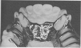
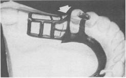
Fig. 5-49 Extension of finishing line to area of pterygomaxillary notch provides butt-type joint for attachment of border portion of acrylic resin base through pterygomaxillary notch (arrows). |
|
particularly useful in preventing distortion of the framework during acrylic resin processing procedures. Tissue stops should engage buccal and lingual slopes of the residual ridge for stability (Fig. 5-50). Altered cast impression procedures often require that tissue stops be augmented subsequent to the development of the altered cast. This can be readily accomplished with |
|
|
|
Chapter 5 |
|
Major and minor connectors |
|
|
|
A |
|
c |
|
F |
|
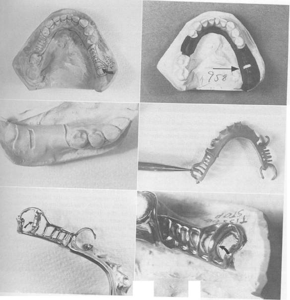
Fig. 5-50 A, Arrow points to location of tissue stop. B, Master cast partially prepared for duplication in refractory investment. Note posteriorly located window cut in relief wax over residual ridge for tissue stop. C, Window in refractory cast that will result in tissue stop when framework is waxed and cast. D, Pencil points to tissue stop as seen from tissue side of recovered cast framework. E, Finished framework. Arrow points to created tissue stop. F, Tissue stop on master cast contacts residual ridge. Remainder of minor connector to attach denture base is elevated from residual ridge that is the thickness of a sheet of baseplate wax. |
|
|
|
|
|
McCracken's removable partial prosthodontics |
|
A |
|
B |
|
Fig. 5-51 A, Lower half of flask in which distal extension denture was invested. Note that terminal portion of minor connector (original tissue stop) is elevated from residual ridge. Framework was developed on cast, with residual ridge recorded in its anatomic form. Residual ridge was later recorded in its functional form by a corrected impression, thus the elevated tissue stop. B, Autopolymerizing acrylic resin is painted on between tissue stop and ridge to maintain position of minor connector during packing and processing procedures for an acrylic resin denture base. |
|
the addition of autopolymerizing acrylic resin (Fig. 5-51). Another integral part of the minor connector designed to retain the acrylic resin denture base is similar to a tissue stop but serves a different purpose. It is located distal to the terminal abutment and is a continuation of the minor connector contacting the guiding plane. Its purpose is to establish a definitive finishing index tissue stop for the acrylic resin base after processing (Fig. 5-52). |
|
FINISHING LINES |
|
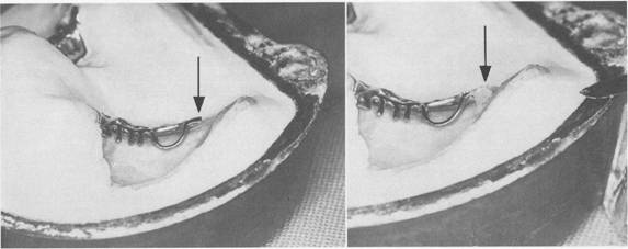
The finishing line junction with the major connector should take the form of an angle not greater than 90 degrees, therefore being somewhat undercut (Fig. 5-53). Of course the medial extent of the minor connector depends on the lateral extent of the major palatal connector. Too little attention is given to this finishing line location in many instances. If the finishing line is located too far medially, the natural contour of the palate will be altered by the thickness of the junction and the acrylic resin supporting the |
|
artificial teeth (Fig. 5-54). If, on the other hand, the finishing line is located too far buccally, it will be most difficult to create a natural contour of the acrylic resin on the lingual surface of the artificial teeth. The location of the finishing line at the junction of the major and minor connector should be based on restoring the natural palatal shape, taking into consideration the location of the replacement teeth. Equal consideration must be given to the junction of minor connectors and bar-type direct retainer arms (Fig. 5-55). These junctions are 90-degree butt-type joints and should follow the guidelines for base contour and clasp length. |
|
REACTION OF TISSUES TO METALLIC COVERAGE |
|
The reaction of tissue to metallic coverage has been the subject of some controversy, particularly in areas at gingival crossings and broad areas of metal contact with tissues. The first of these tissue reactions is pressure resulting from lack of support. If relief over gingival crossings and other areas of contact with |
|
|
|
|
|
Chapter |
|
Major and minor connectors |
|
|
|
c |
|
B |
|
A |
|
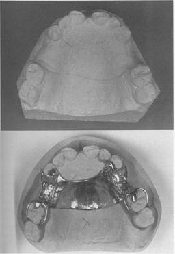
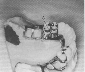
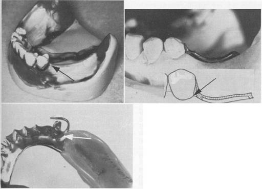
Fig. 5-52 Finishing index tissue stop. A, Blocked out and relieved master cast. Note small window in relief wax over residual ridge just distal to first premolar. Undercut on distal has been blocked out parallel to path of placement, including gingival crevice. Anterior portion of window does not violate parallel blockout. Final casting will fill window space. B, Photograph of cut-away framework casting and schematic of minor connectors for attaching denture base. Note anterior portion of minor connector contacts guiding plane of abutment and residual ridge parallel to path of placement. Processing of acrylic resin bases should not fill gingival undercut area on distal of premolar (arrows). C, View of finishing index tissue stop from tissue side of base. Base was finished to the finishing stop, thereby maintaining planned relationship of anterior portion of denture base to abutment tooth. |
|
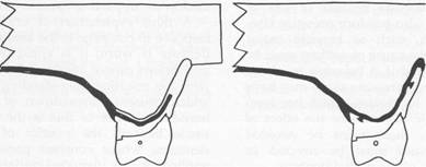
Fig. 5-53 Frontal sections through lingual finishing lines of palatal major connectors. Figure on right is through full cast metal base major connector; figure on left is through acrylic resin denture base. In both situations, location of finishing lines minimizes bulk of acrylic resin attaching the artificial teeth. Palatal contours are restored, enhancing speech and contributing to a natural feeling for the patient. |
|
|
|
|
|
|
|
McCracken's removable partial prosthodontics |
|
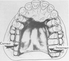
Fig. 5-54 Junction of major connector and minor connector at palatal finishing lines should be located 2 mID medial from an imaginary line that would contact lingual surfaces of missing posterior teeth. Finish line on right is too far toward midline of palate. Natural contours of palate will be altered. |
|
tissues that are incapable 0"£ supporting the prosthesis is inadequate, then impingement on these tissues is inevitable. Impingement will likewise occur if the denture settles because of loss of tooth and/or tissue support. This may be caused by failure of the rest areas as a result of improper design or caries involvement, fracture of the rest itself, or intrusion of abutment teeth under occlusal loading. It is the responsibility of the dentist to provide and maintain adequate relief and adequate tooth support. Settling of the denture because of loss of tissue support may also produce pressure elsewhere in the arch, such as beneath major connectors. Again, the cause of settling must be prevented or corrected if it becomes manifest. Fisher has shown that pressure alone may have a nonspecific effect on tissues, which has been mistaken for allergic response or the effect of coverage. Pressure, then, must be avoided whenever oral tissues must be covered or crossed by elements of the partial denture. The second reason is uncleanliness. It is known that tissues respond unfavorably to an accumulation of food debris and bacteria. Coverage of oral tissues with dentures that are not |
|
Fig. 5-55 Note direct retainer arm tapers from its tip to finishing line. Without a finishing line (arrow) at junction of direct retainer arm and minor connector for denture base, flexing of direct retainer arm could create minute cracks in anterior border of denture base, thus contributing to chipping of borders, as well as unhygienic condition from food particle impaction. |
|
kept clean irritates those tissues, not because they are covered but because of the accumulation of irritating factors. This has led to a misinterpretation of the effect of tissue coverage by prosthetic restorations. An additional factor of the cleanliness issue is the problem of polishing and finishing compounds being embedded in microfissures and cracks that result from the framework casting process. These compounds have caused irritation and inflammation to supporting tissues. A third explanation of unfavorable tissue response to coverage is the amount of time the denture is worn. It is apparent that mucous membranes cannot tolerate this constant contact with the resulting long-standing inflammation, which causes a breakdown of the epithelial barrier. Evidence of this is the appearance of tissue beneath the pontics of fixed partial dentures; where constant pressure has been applied. A raw, denuded surface is visible on removal of the fixed restoration. The same thing can occur beneath removable prostheses if they are allowed to remain against the tissue long enough. |
|
Some patients become so accustomed to wearing a removable restoration that they neglect to remove it often enough to give the tissues any respite from constant contact. This is frequently true when anterior teeth are replaced by the partial denture and the individual does not allow the prosthesis to be out of the mouth at any time except in the privacy of the bathroom during toothbrushing. Living tissue should not be covered all the time or changes in those tissues will occur. Partial dentures should be removed for several hours each day so that the effects of tissue contact can subside and the tissues can return to a normal state. Clinical experience with the use of linguo plates and complete metallic palatal coverage has shown conclusively that when factors of pressure, cleanliness, and time are controlled, tissue coverage is not in itself detrimental to the health of oral tissues. |
|
MAJOR CONNECTORS IN REVIEW* |
|
It is only through the rigidity of the major connector that all other components of the partial denture may be effective. Design of major connectors must be deter mined during diagnostic and treatment planning phases because mouth preparation proce |
|
'A review of factors influencing the choice of design, definitive location, and average pattern specifications 6f various major connectors is now presented in a rather condensed version. It is hoped that such a presentation coming after a general discussion will be a meaning ful guide to student-dentists in their decision-making processes |
|
Chapter 5 |
|
Major and minor connectors |
|
|
|
dures depend in part on the contemplated design of major connectors. Operable tori or other bony exostoses should be removed to avoid compromises in the design and for optimum location of major connectors. Major connectors must be located in favorable relation to moving tissues and, at the same time, must avoid impingement of gingival tissues No component of a removable partial denture framework may engage undercuts other than the terminal portions of retentive direct retainer arms. Adequate but not excessive tissue relief beneath major connectors, when indicated, avoids the need for later adjustments to provide relief after tissue damage has occurred. Suffi cient relief must be provided beneath major connectors to avoid any settling into nonresilient areas such as inoperable tori, other exostoses, or prominent median palatal suture areas. The amount of such relief is determined by ascertaining the difference in displaceability of the tissues to be covered and those of the primary stress-bearing areas of residual ridges. In addi tion, the quality of support anticipated by using other elements of the framework to resist horizontal rotations and displacement toward the tissues is another factor to be considered in the amount of relief to be provided for any type of major connector. Relief of free gingival margins must be provided for any component of the framework, in addition to relief for the denture bases. This support is derived primarily from components terminating in rest seats specifically prepared to receive them. Anatomic replica patterns for palatal major connectors permit the faithful reproduction of palatal contours and may be made thinner without sacrificing rigidity. |
|
|
|
|
|
|
|
McCracken's removable partial prosthodontics |
|
MANDIBULAR LINGUAL BAR |
|
INDICATIONS FOR USE: The lingual bar should be used for mandibular removable partial dentures where sufficient space exists between the slightly elevated alveolar lingual sulcus and the lingual gingival tissues. |
|
CHARACTERISTICS AND LOCATION: (1) Half-pear shaped with bulkiest portion inferiorly located. (2) Superior border tapered to soft tissue. (3) Superior border located at least 4 mm inferior to gingival margins and more if possible. (4) Inferior border located at the ascertained lteight of the alveolar lingual sulcus when the patient's tongue is slightly elevated. |
|
BLOCKOUT AND RELIEF OF MASTER CAST: (1) All tissue undercuts parallel to path of placement. (2) An additional thickness of 32-gauge sheet wax when the lingual surface of the alveolar ridge is either undercut or parallel to the path of placement (see Figs. 11-24 and 11-25). (3) No relief is necessary when the lingual surface of the alveolar ridge slopes inferiorly and posteriorly. (4) One thickness of baseplate wax over basal seat areas (to elevate minor connectors for attaching acrylic resin denture bases). |
|
WAXING SPECIFICATIONS: (1) Six-gauge, half-pearshaped wax form reinforced by 22- to 24-gauge sheet wax or similar plastic pattern adapted to the design width. (2) Long bar requires more bulk than short bar; however, cross-sectional shape is unchanged. |
|
FINISHING LINES: Butt-type joint(s) with minor connec tor(s) for retention of denture base(s). |
|
MANDIBULAR LINGUOPLATE |
|
INDICATIONS fOR USE: (1) Where the alveolar lingual sulcus so closely approximates the lingual gingival crevices that adequate width for a rigid lingual bar does not exist. (2) In those instances in which the residual ridges in Class I arch have undergone such vertical resorption that they will offer only minimal resistance to horizontal rotations of the denture through its bases. (3) For using periodontally weakened teeth in group function to furnish support to the prosthesis and to help resist horizontal (off-vertical) rotation of the distal extension type of denture. (4) When the future replacement of one or more incisor teeth will be facilitated by the addition of retention loops to an existing linguoplate. |
|
CHARACTERISTICS AND LOCATION: (1) Half-pear shaped with bulkiest portion inferiorly located. (2) Thin metal apron extending superiorly to contact cingula of anterior teeth and lingual surfaces of involved posterior teeth at their height of contour. (3) Apron extended interproximally to the height of contact points, that is, closing interproximal spaces. (4) Scalloped contour of apron as dictated by interproximal blockout. (5) Superior border finished to continuous plane with contacted teeth. (6) Inferior border at the ascertained height of the alveolar lingual sulcus when the patient's tongue is slightly elevated. |
|
BLOCKOUT AND RELIEF OF MASTER CAST: (1) All involved undercuts of contacted teeth parallel to the path of placement. (2) All involved gingival crevices. (3) Lingual surface of alveolar ridge and basal seat areas the same as for a lingual bar. |
|
WAXING SPECIFICATIONS: (1) Inferior border-6-gauge, half-pear-shaped wax form reinforced with 24gauge sheet wax or similar plastic pattern. (2) Apron-24-gauge sheet wax. |
|
FINISHING LINES: Butt-type joint(s) with minor connec tor(s) for retention of denture base(s). |
|
|
|
|
|
MANDIBULAR SUBLINGUAL BAR |
|
INDICATIONS FOR USE: (1) The sublingual bar should be used for mandibular removable partial dentures where the height of the floor of the mouth, in relation to the free gingival margins, will be less than 6 mm. It may also be indicated whenever it is desirable to keep the free gingival margins of the remaining anterior teeth exposed and there is inadequate depth of the floor of the mouth to place a lingual bar. |
|
CONTRAINDICATIONS FOR USE: Remaining natural ante rior teeth severely tilted toward the lingual. |
|
CHARACTERISTICS AND LOCATION: The sublingual bar is essentially the same half-pear shape as a lingual bar except that the bulkiest portion is located to the lingual and the tapered portion is toward the labial. The superior border of the bar should be at least 3 mm from the free gingival margin of the teeth. The inferior border is located at the height of the alveolar lingual sulcus when the patient's tongue is slightly elevated. This requires a functional impression of the lingual vestibule to accurately register the height of the vestibule. |
|
BWCKOUT AND RELIEF OF MASTER CAST: (1) All tissue undercuts parallel to path of placement. (2) An additional thickness of 32-gauge sheet wax when the lingual surface of the alveolar ridge is either undercut or parallel to the path of placement. (3) One thickness of baseplate wax over basal seat areas (to elevate minor connectors for attaching acrylic resin denture bases). |
|
WAXING SPECIFICATIONS: (1) Six-gauge, half-pearshaped wax form reinforced by 22- to 24-gauge sheet wax or similar plastic pattern adapted to design width. (2) Long bar bulkier than short bar; however, cross-sectional shape unchanged. |
|
FINISHING LINES: Butt-type joint(s) with minor connec torrs) for retention of denture base(s). |
|
Chapter 5 |
|
Major and minor connectors |
|
|
|
MANDIBULAR LINGUAL BAR WITH CONTINUOUS BAR (CINGULUM BAR) |
|
INDICATIONS FOR USE: (1) When a linguoplate is otherwise indicated but the axial alignment of anterior teeth is such that excessive blockout of interproximal undercuts would be required. (2) When wide diastemata exist between mandibular anterior teeth and a linguoplate would objectionably display metal in a frontal view. |
|
CHARACTERISTICS AND LOCATION: (1) Conventionally shaped and located same as lingual bar major connector component when possible. (2) Thin, narrow (3 mm) metal strap located on cingula of anterior teeth, scalloped to follow interproximal embrasures with inferior and superior borders tapered to tooth surfaces. (3) Originates bilaterally from incisal, lingual, or occlusal rests of adjacent principal abutments. |
|
BLOCKOUT AND RELIEF OF MASTER CAST: (1) Lingual surface of alveolar ridge and basal seat areas same as for lingual bar. (2) No relief for continuous bar except blockout of interproximal spaces parallel to path of placement. |
|
WAXING SPECIFICATIONS: (1) Lingual bar major connector component waxed and shaped same as lingual bar. (2) Continuous bar pattern formed by adapting two strips (3 mm wide) of 28-gauge sheet wax, one at a time, over the cingula and into interproximal embrasures. |
|
FINISHING LINES: Butt-type joint(s) with minor connec torrs) for retention of denture base(s). |
|
|
|
|
|
|
|
McCracken's removable partial prosthodontics |
|
MANDIBULAR CONTINUOUS BAR (CINGULUM BAR) |
|
INDICATIONS FOR USE: When a lingual plate or sublingual bar is otherwise indicated but the axial alignment of the anterior teeth is such that the excessive blockout of interproximal undercuts would be required. |
|
CONTRAINDICATIONS: (1) Anterior teeth severely tilted to the lingual. (2) When wide diastemata exist between the mandibular anterior teeth and the cingulum bar would objectionably display metal in a frontal view. . |
|
CHARACTERISTICS AND LOCATION: (1) Thin, narrow (3 mm) metal strap located on cingula of anterior teeth, scalloped to follow interproximal embrasures with inferior and superior borders tapered to tooth surfaces. (2) Originates bilaterally from incisal, lingual, or occlusal rests of adjacent principal abutments. |
|
BLOCKOUT AND RELIEF OF MASTER CAST: No relief for cingulum bar except blockout of interproximal spaces parallel to the path of placement. |
|
WAXING SPECIFICATIONS: Cingulum bar pattern formed by adapting two strips (3 mm wide) of 28-gauge sheet wax, one at a time, over the cingula and into interproximal embrasures. |
|
FINISHING LINES: Butt-type joint(s) with minor connec tor(s) for retention of denture base(s). |
|
MANDIBULAR LABIAL BAR |
|
INDICATIONS FOR USE: (1) When lingual inclinations of remaining mandibular premolar and incisor teeth cannot be corrected, preventing the placement of a conventional lingual bar connector. (2) When severe lingual tori cannot be removed and prevent the use of a lingual bar or lingual plate major connector. (3) When severe and abrupt lingual tissue undercuts make it impractical to use a lingual bar or lingual plate major connector. |
|
CHARACTERISTICS AND LOCATION: (1) Half-pear shaped with bulkiest portion inferiorly located on the labial and buccal aspects of the mandible. (2) Superior border tapered to soft tissue. (3) Superior border located at least 4 mm inferior to labial and buccal gingival margins and more if possible. (4) Inferior border located in the labial-buccal vestibule at the juncture of attached (immobile) and unattached (mobile) mucosa. |
|
BLOCKOUT AND RELIEF OF MASTER CAST: (1) All tissue undercuts parallel to path of placement, plus an additional thickness of 32-gauge sheet wax when the labial surface is either undercut or parallel to the path of placement. (2) No relief necessary when the labial surface of the alveolar ridge slopes inferiorly to the labial or buccal. (3) Basal seat areas same as for lingual bar major connector. |
|
WAXING SPECIFICATIONS: (1) Six-gauge, half-pearshaped wax form reinforced with 22- to 24-gauge sheet wax or similar plastic pattern. (2) Long bar requires more bulk than short bar; however, cross-sectional shape unchanged. (3) Minor connectors joined with occlusal or other superior components by a labial or buccal approach. (4) Minor connectors for base attachment joined by a labial or buccal approach. |
|
FINISHING LINES: Butt-type joint(s) with minor connec tor(s) for retention of denture base(s). |
|
|
|
|
|
SINGLE PALATAL STRAP-TYPE MAJOR CONNE_TOR |
|
INDICATIONS FOR USE: Bilateral edentulous spaces of short span in a tooth-supported restoration. |
|
CHARACTERISTICS AND LOCATION: (1) Anatomic replica form. (2) Anterior border follows the valleys between rugae as nearly as possible at right angles to median suture line. (3) Posterior border at right angle to median suture line. (4) Strap should be 8 rom wide or approximately as wide as the combined width of a maxillary premolar and first molar. (5) Confined within an area bounded by the four principal rests. |
|
BWCKOUT AND RELIEF OF MASTER CAST: (1) Usually none required except slight relief of elevated medial palatal raphe or any exostosis crossed by the connector. (2) One thickness of baseplate wax over basal seat areas (to elevate minor connectors for attaching acrylic resin denture bases). |
|
BEADING: See Figs. 5-39 to 5-42. |
|
WAXING SPECIFICATIONS: (1) Anatomic replica pattern equivalent to 22- to 24-gauge wax, depending on arch width. |
|
FINISHING LINES: (1) Undercut and slightly elevated. (2) No farther than 2 mm medial from an imaginary line contacting lingual surfaces of principal abutments and teeth to be replaced. (3) Follow curvature of arch. |
|
Chapter 5 |
|
Major and minor connectors |
|
|
|
SINGLE BROAD PALATAL MAJOR CONNECTOR |
|
INDICATIONS FOR USE: (1) Class I partially edentulous arches with residual ridges that have undergone little vertical resorption and will lend excellent support. (2) V- or U-shaped palates. (3) Strong abutments (single or made so by splinting). (4) More teeth in arch than six remaining anterior teeth. (5) Direct retention not a problem. (6) No interfering tori. |
|
CHARACTERISTICS AND LOCATION: (1) Anatomic replica form. (2) Anterior border following valleys of rugae as near right angle to median suture line as possible and not extending anterior to occlusal rests or indirect retainers. (3) Posterior border located at junction of hard and soft palate but not extended onto soft palate; at right angle to the median suture line; extended to pterygomaxillary notches. |
|
BWCKOUT AND RELIEF OF MASTER CAST: (1) Usually none required except relief of elevated median palatal raphe or any small exostoses covered by the connector. (2) One thickness of baseplate wax over basal seat areas (to elevate minor connectors for attaching acrylic resin denture bases). |
|
BEADING: See Figs. 5-39 to 5-42. |
|
WAXING SPECIFICATIONS: Anatomic replica pattern equivalent to 24-gauge sheet wax thickness. |
|
FINISHING LINES: (1) Provision for butt-type joint at pterygomaxillary notches. (2) Undercut and slightly elevated. (3) No farther than 2 mm medial from an imaginary line contacting the lingual surfaces of the missing natural teeth. (4) Following curvature of arch. |
|
|
|
|
|
|
|
|
|
McCracken's removable partial prosthodontics |
|
ANTERIOR-POSTERIOR STRAP-TYPE MAJOR CONNECTOR |
|
INDICATIONS FOR USE: (1) Class I itnd II arches in which excellent abutment and residual ridge support exists, and direct retention can be made adequate without the need for indirect retention. (2) Long edentulous spans in Class II, modification 1 arches. (3) Class IV arches in which anterior teeth must be replaced with a removable partial denture. (4) Inoperable palatal tori that do not extend posteriorly to the junction of the hard and soft palates. |
|
CHARACTERISTICS AND LOCATION: (1) Parallelogram shaped and open in center portion. (2) Relatively narrow (8 to 10 mm) anterior and posterior palatal straps. (3) Lateral palatal straps (7 to 9 mm) broad and parallel to curve of arch; minimum of 6 mm from gingival crevices of remaining teeth. (4) Anterior palatal strap: anterior border not placed farther anteriorly than anterior rests and never closer than 6 mm to lingual gingival crevices; follows the valleys of the rugae at right angles to the median palatal suture. Posterior border, if in rugae area, follows valleys of rugae at right angles to the median palatal suture. (5) Posterior palatal connector: posterior border located at junction of hard and soft palates and at right angles to median palatal suture and extended to hamular notch area(s) on distal extension side(s). (6) Anatomic replica or matte surface. |
|
BWCKOUT AND RELIEF OF MASTER CAST: (1) Usually none required except slight relief of elevated median palatal raphe where anterior or posterior straps cross the palate. (2) One thickness of baseplate wax over basal seat areas (to elevate minor connectors for attaching acrylic resin denture bases). |
|
BEADING: See Figs. 5-39 to 5-42. |
|
WAXING SPECIFICATIONS: (1) Anatomic replica patterns or matte surface forms of 22-gauge thickness. (2) Posterior palatal component-A strap of 22gauge thickness, 8 to 10 mm wide (a half-oval form of approximately 6-gauge thickness and width) may also be used. |
|
FINISHING LINES: Same as for single broad palatal major connector. |
|
|
|
|
|
COMPLETE PALATAL COVERAGE MAJOR CONNECTOR |
|
INDICATIONS FOR USE: (1) In most situations in which only some or all anterior teeth remain. (2) Class II arch with a large posterior modification space and some missing anterior teeth. (3) Class I arch with one to four premolars and some or all anterior teeth remaining, and abutment support is poor and cannot otherwise be enhanced; residual ridges have undergone extreme vertical resorption; direct retention is difficult to obtain. (4) In the absence of a pedunculated torus. . |
|
CHARACTERISTICS AND LOCATION: (1) Anatomic replica form for full palatal metal casting supported anteriorly by positive rest seats. (2) Palatallinguoplate supported anteriorly and designed for the attachment of acrylic resin extension posteriorly. (3) Contacts all or almost all of the teeth remaining in the arch. (4) Posterior border: terminates at the junction of the hard and soft palates; extended to hamular notch area(s) on distal extension siders); at a right angle to median suture line. |
|
BWCKOUT AND RELIEF OF MASTER CAST: (1) Usually none required except relief of elevated median palatal raphe or any small palatal exostosis. (2) One thickness of baseplate wax over basal seat areas (to elevate minor connectors for attaching acrylic resin denture bases). |
|
BEADING: See Figs. 5-39 to 5-42. |
|
WAXING SPECIFICATIONS: (1) Anatomic replica pattern equivalent to 22- to 24-gauge sheet wax thickness. (2) Acrylic resin extension from linguoplate the same as for a complete denture. |
|
FINISHING LINES: As illustrated here and previously discussed. |
|
Chapter 5 |
|
Major and minor connectors |
|
|
|
U-SHAPED PALATAL MAJOR CONNECTOR |
|
This connector should be used only in those situations in which inoperable tori extend to the posterior limit of the hard palate. The U-shaped palatal major connector is the least favorable design of all palatal major connectors because it lacks the rigidity of other types of connectors. Where it must be used, any portion of the connector extending anteriorly from the principal occlusal rests must be supported by indirect retainers. Anterior border areas of this type of connector must be kept at least 6 mm away from adjacent teeth. If for any reason the anterior border must contact the remaining teeth, the connector must again be supported by rests placed in properly prepared rest seats. It should never be supported even temporarily by inclined lingual surfaces of anterior teeth. Waxing specifications, finishing lines, etc., are the same as for full palatal castings or other similar major connectors previously discussed. |
|
|
|
McCracken's removable partial prosthodontics |
|
SELF-ASSESSMENT AIDS 1. A Class I removable partial denture should have seven components. Name the components. 2. Define the term major connector in your own words. 3. Several desirable characteristics of major connectors are listed in the first few pages of Chapter 5. What are five of these characteristics? 4. What purposes are served by rigid major connectors as contrasted with flexible connectors? 5. Major connectors should be located in a favorable relation to moving tissues, gingival tissues, and areas of bony and tissue prominences. What difficulties would the patient encounter if the preceding guidelines are not carried out? 6. Name and draw the cross-sectional form of the basic mandibular major connector. 7. Margins of major connectors adjacent to gingival tissues should be located far enough from those tissues to avoid possible impingement when the denture rotates from functional and parafunctional forces. The superior border of a lingual bar should be located at least - mm from gingival crevices. 8. The inferior border of a lingual bar is located as far inferiorly as possible without encroaching on the movable tissues in the alveolar lingual sulcus. Describe two methods by which the location of the inferior border can be accurately determined. 9. Sufficient relief must be provided beneath a major connector to avoid impingement and! or displacement of soft tissues resulting in an inflammatory response. What is meant by the word relief? Rationalize planned relief for a lingual bar and give quantitative rules of thumb that depend on the contour of the anterior, lingual alveolar ridge. 10. Discuss those clinical observations that indicate the choice of a lingual bar as a major connector. 11. What is the form of a mandibular linguo plate major connector? 12. Give four clinical observations that indicate use of a linguoplate rather than a lingual bar as a major connector. |
|
13. Draw a sagittal section through a cast that shows the basic form of a linguoplate. 14. What is the difference in determining the location of the inferior borders for lingual bars and linguoplates? 15. Describe the superior extent of the apron portion of a linguoplate in relation to the lingual surfaces of teeth contacted by the major connector. 16. What are the indications for use of a lingual bar-continuous bar type of major connector? 17. Interpret in your own words the rationale of this statement made by McCracken: "No component of a partial denture should be added arbitrarily or conventionally. Each component should be added for a good reason and to serve a definite purpose." 18. How may a linguoplate be modified to avoid an overdisplay of metal when used on an arch in which wide diastemata exist between anterior teeth? 19. The dentist alone is responsible for the design of the restoration, which is based on both biologic and mechanical principles. Give the dimensional specifications of the wax patterns of mandibular major connectors. 20. At what point in treating the partially edentulous patient must the choice of maxillary and mandibular major connectors be made? Explain. 21. There are basically four types of maxillary major connectors. Name and describe them. 22. What objections are usually manifested in use of the single palatal bar-type major connector? 23. Which type of palatal major connector is probably the most rigid and at the same time covers the smallest amount of soft tissues? 24. In what situations would one be most likely to use a single palatal strap-type major connector? 25. There are definite rules of thumb for the location of the anterior and posterior borders of all palatal major connectors. Describe the relationship of the borders to rugae, junction of hard and soft palates, gingival crevices, pterygomaxillary notches, and palatal tori. |
|
|
|
|
|
tiC |
|
CL |
|
>_w.v> .H_ ___L5H VL YUHHCU HCC')VL LVUU<::Ltors on a diagnostic cast of a Class I maxillary arch. What is a minor connector? What are the functions of minor connectors? Should minor connectors be structurally rigid or flexible? Why? Describe the shape of a minor connector contacting axial surfaces of adjacent abutments at interproximal areas. TrI"nHt" civ At fho o;_hf _;_A_ _A__A__A__ ;_ |
|
<\That modification in the design of a minor :onnector was suggested by Radford? What Ire the suggested advantages and the disad'antages of this variation in design? What is he limitation of this design? .1inor connectors used to attach acrylic resin lenture bases to major connectors should be _cated on both buccal and lingual sides of he residual ridge. Why? :tate rules of thumb for the form and length ,f minor connectors connecting acrylic resin lenture bases to major connectors. Vhat advantages accrue to the restoration 'y having minor connectors for acrylic resin lenture bases attached to the major connecJr in a butt-type joint? )escribe the best location for palatal finish19 lines at the junction of major and minor nnnor+Arc J-:rAU' riA "An rlo_O__;_A _h;_ |
|
pnmum lOcatIOn on a cast( Why IS It nportant that the natural contour of the ala tal vault be restored with a removable _storation? 1 addition to a more natural feeling con)Ur, what other factors may be achieved by le use of anatomic replica patterns for ala tal major connectors? Ihat are three ways to increase the bond :rength between the minor connectors and le acrylic resin denture bases? How much f],o], ,. .,. . |
|
|
|
|
|
26. Can adequate support be obtained by resting the palatal major connector on tooth inclines? Why? 27. Rationalize this statement: "Either support the connector by definite rests on the teeth contacted, bridging the gingivae with adequate relief, or locate the connector far enough away from the gingivae to avoid any possible restriction of blood supply and entrapment of food debris." 28. Why should all gingival crossings by components of a framework be abrupt and at right angles to the major connector and bridge the gingivae with adequate relief? 29. Describe a continuous bar mandibular major connector and list the indications for its use. 30. Describe a sublingual bar mandibular major connector and list the indications for its use. 31. What clinical and diagnostic observations would lead to the selection of an anterior-posterior palatal strap-type major connector? . 32. Under what circumstances is full palatal coverage by the major connector indicated? 33. Describe a palatallinguoplate major connec tor and explain why such a design would be selected. 34. Describe the five steps outlined by Blatter fein for the design of palatal major connec tors on a diagnostic cast of a Class I maxillary arch. 35. What is a minor connector? 36. What are the functions of minor connectors? 37. Should minor connectors be structurally rigid or flexible? Why? 38. Describe the shape of a minor connector contacting axial surfaces of adjacent abut ments at interproximal areas. 39. Identify six of the eight minor connectors in this drawing. |
|
Chapter 5 |
|
Major and minor connectors |
|
|
|
40. What modification in the design of a minor connector was suggested by Radford? What are the suggested advantages and the disadvantages of this variation in design? What is the limitation of this design? 41. Minor connectors used to attach acrylic resin denture bases to major connectors should be located on both buccal and lingual sides of the residual ridge. Why? 42. State rules of thumb for the form and length of minor connectors connecting acrylic resin denture bases to major connectors. 43. What advantages accrue to the restoration by having minor connectors for acrylic resin denture bases attached to the major connector in a butt-type joint? 44. Describe the best location for palatal finishing lines at the junction of major and minor connectors. How do you determine this optimum location on a cast? Why is it important that the natural contour of the palatal vault be restored with a removable restoration 45. In addition to a more natural feeling contour, what other factors may be achieved by the use of anatomic replica patterns for palatal major connectors? 46. What are three ways to increase the bond strength between the minor connectors and the acrylic resin denture bases? How much is the bond strength increased? |
|