|
|
|
Major and minor connectors |
|
Major Connectors Mandibular major connectors Maxillary major connectors Minor Connectors Functions |
|
Form and location Tissue stops |
|
C |
|
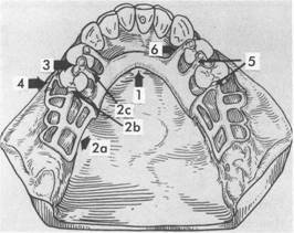
omponents of a typical removable partial denture are illustrated in Fig. 5-1, A. 1. Major connectors 2. Minor connectors 3. Rests 4. Direct retainers 5. Stabilizing or reciprocal components (as parts of a direct retainer assembly) 6. Indirect retainers (if the prosthesis has one or more distal extension bases) 7. One or more bases, each supporting one to several replacement teeth (Fig. 5-1, Band C) In this chapter, major and minor connectors are considered separately as to their function, location, and design criteria, keeping in mind both biologic and mechanical considerations. Other components are presented in designated chapters. |
|
MAJOR CONNECTORS |
|
A major connector is the component of the partial denture that connects the parts of the prosthesis located on one side of the arch with |
|
Finishing Lines Reaction of Tissues to Metallic Coverage Major Connectors in Review Self-Assessment Aids |
|
those on the opposite side. It is that unit of the partial denture to which all other parts are directly or indirectly attached (Fig. 5-2). This component also provides the cross-arch stability to help resist displacement by functional stresses. The major connector may be compared with the frame of an automobile or with the foundation of a building. Major connectors must be rigid so that forces applied to any portion of the denture can be effectively distributed over the entire supporting structures. Rigidity of the major connector resists flexing and torque that could be transmitted to abutment teeth and other structures as destructive forces. It is through the major connector that other components of the partial denture become unified and effective. If they are attached to, or originate from, a flexible connector, the effectiveness of components can jeopardize the supporting oral structures and can be a detriment to the comfort of the patient. Failure of the major connector to provide rigidity may be manifest by traumatic damage to periodontal support of abutment teeth, injury to residual ridges, or |
|
|
|
|
|
|
|
|
|
|
|
|
|
|
|
McCracken's removable partial prosthodontics |
|
A |
|
B |
|
A |
|
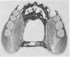
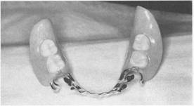
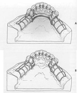
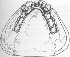
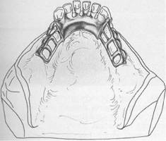
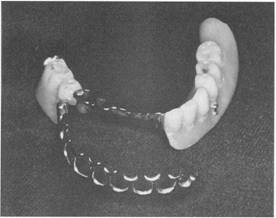
Fig. 5-1 A, Framework for mandibular removable partial denture with the following components: 1, lingual bar major connector; 2a, minor connector by which the acrylic resin denture base will be attached; 2b, minor connector, proximal plate, which is part of clasp assembly; 2c, minor connector used to connect rests to major connectors; 3, occlusal rests; 4, direct retainer arm, which is part of the total clasp assembly; 5, stabilizing or reciprocal components of clasp assembly (two minor connectors and two rests); and 6, an indirect retainer consisting of a minor connector and an occlusal rest. B, Maxillary removable partial denture with acrylic resin denture bases supporting artificial posterior teeth. Bases are attached to metal framework by ladder like minor connectors similar to those seen in 2a. C, Mandibular bilateral distal extension removable partial denture with acrylic resin denture bases supporting artificial posterior teeth. |
|
c |
|
B |
|
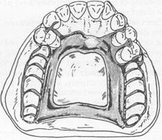
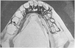
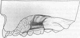
Fig. 5-2 A, Lingual bar major connector for mandibular removable partial denture framework. It rigidly joins cast base on right side to other elements of the framework on left side. D, Anterior-posterior strap-type n"laxillary major connector for a Class I partially edentulous arch. This is a rigid type of major connector and covers only a small portion of palatal tissue. |
|
impingement of underlying tissues. It is the dentist's responsibility to ensure that the appropriate design and fabrication of the major connector are accomplished. Location Major connectors should be designed and located with the following guidelines in mind: 1. Major connectors should be free of movable tissues. 2. Impingement of gingival tissues should be avoided. 3. Bony and soft tissue prominences should be avoided during placement and removaL 4. Relief should be provided beneath a major connector to prevent its settling into areas of possible interference, such as inoperable tori or elevated palatal median sutures. 5. Major connectors should be located and/or relieved to prevent impingement of tissues as the distal extension denture rotates in function. Planned relief beneath the major connector, when indicated, avoids the need for later adjustment to provide relief of the prosthesis after tissue damage has occurred. In addition to being time consuming, grinding to provide relief from impingement may seriously weaken the major connector, result in flexibility, or possibly lead to fracture. Major connectors should be carefully designed for proper shape, thickness, and location. Alteration of these dimensions by grinding can only be detrimentaL Relief is covered at the end of this chapter and expanded in Chapter 11. Margins of major connectors adjacent to gingival tissues should be located far enough from those tissues to avoid any possible impingement. To accomplish this, it is recommended that the superior border of a lingual bar connector be located a minimum of 4 mm below the gingival margin(s) (Fig. 5-3). The limiting factor, inferiorly, is the height of the moving tissues in the floor of the mouth. Because the connector must have sufficient width and bulk to provide rigidity, a linguoplate, a sublingual bar, or a cingulum bar should be used when there is insufficient space for a lingual bar. In the maxillary arch, because there are no moving tissues in the palate as in the floor of the |
|
Chapter 5 |
|
Major and minor connectors |
|
|
|
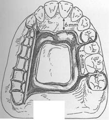
mouth, the borders of the major connector may be placed well away from gingival tissues. Structurally the tissues covering the palate are well suited for placement of the connector because of the presence of firm submucosal connective tissue and an adequate, deep blood supply. However, when soft tissue covering the median portion of the palate is less displaceable than the tissue covering the residual ridge, varying amounts of relief under the connectors must be provided to avoid impingement of tissue with its resulting sequelae. The amount of relief required is directly proportional to the difference in displaceability of tissues covering the medial palatal raphe and tissues covering the residual ridges. The gingival tissues, on the other hand, must have an unrestricted superficial blood supply to remain healthy. To accomplish this, it is recommended that the borders of the palatal connector be placed a minimum of 6 mm away from gingival margins and be located parallel to the mean curve of the free gingival margin. Minor connectors that must cross gingival tissues should do so abruptly, joining the major connector at nearly a right angle (Fig. 5-4). In this way the maximum freedom of gingival tissues is ensured. Except for a palatal torus or prominent median palatal suture area, palatal connectors ordinarily require no relief nor is relief desirable. Intimate contact between the connector and the supporting tissues adds much to the support, stability, and retention of the denture. Except for gingival areas, intimacy of contact elsewhere in the palate is not in itself detrimental to the health of the tissues, if rests are provided on abutment teeth to prevent settling in a tissueward direction. An anterior palatal strap or the anterior border of a palatal plate also should be located as far posteriorly as possible to avoid interference with the tongue in the rugae area. It should be uniformly thin or straplike, rather than half-oval, and should be located so that its anterior border follows the contours between crests of the rugae. The anterior border of such palatal major connectors will therefore be irregular in outline as it follows the contours between the rugae. The tongue may then pass from one ruga prominence to another without |
|
|
|
|
|
|
|
|
|
|
|
|
|
|
|
|
|
McCracken's removable partial prosthodontics |
|
4mm |
|
Half-pear-shaped lingual bar pattern |
|
Path of placement |
|
c |
|
Sublingual bar |
|
L |
|
|
|
Linguoplate pattern |
|
|
|
<; _ ; |
|
Rounded afte being cast in metal |
|
|
|
A |
|
Rounded ake being cast in metal |
|
B |
|
Continuous (cingulum) bar |
|
-\ D |
|
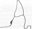
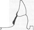
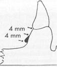
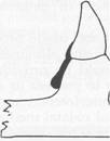
Fig. 5-3 A, Lingual bar major connector should be located at least 4 mm inferior to gingival margins and more if possible. The vertical height of a finished lingual bar should be at least 4 mm for strength and rigidity. If less than 8 mm exists between gingival margins and movable floor of mouth, a linguoplate (B), a sublingual bar (C), or a continuous bar (D) is preferred as a major connector. The inferior border of mandibular major connectors should be gently rounded after being cast to eliminate a sharp edge. |
|
encountering the border of the denture. When a ruga crest must be crossed by the connector border, it should be done abruptly, avoiding the crest as much as possible. The posterior limitation of a maxillary major connector should be just anterior to the vibrating line. A rule to be used throughout partial denture design is as follows: Try to avoid adding any part of the denture framework to an already convex surface. Rather, try to use existing contours and embrasures for the location of component parts of the framework. All compo |
|
nents should be tapered where they join convex surfaces. Characteristics of major connectors contributing to the maintenance of health of the oral environment and the well-being of the patient may be listed as follows: 1. Made from an alloy compatible with oral tissues 2. Rigid and uses the principles of broad distribution of stress Does not interfere with and is not irritating to the tongue |
|
|
|
. __0 |
|
|
|
Fig. 5-4 Palatal major connector should be located at least 6 mm away from gingival margins and parallel to their mean curvature. All adjoining minor connectors should cross gingival tissues abruptly and should join major connectors at nearly a right angle. |
|
4. Does not substantially alter the natural contour of the lingual surface of the mandibular alveolar ridge or of the palatal vault 5. Does not impinge on oral tissues when the restoration is placed, is removed, or rotates in function 6. Covers no more tissue than is absolutely necessary 7. Does not contribute to the retention or trapping of food particles 8. Has support from other elements of the framework to minimize rotation tendencies in function 9. Contributes to the support of the prosthesis |
|
Mandibular major connectors Six types of mandibular major connectors are: 1. Lingual bar (Fig. 5-5, A) 2. Sublingual bar (Fig. 5-5, B) 3. Lingual bar with cingulum bar (continuous bar)(Fig. 5-5, C) 4. Cingulum bar (continuous bar) (Fig. 5-5, D) 5. Linguoplate (Fig. 5-5, E) 6. Labial bar (Fig. 5-5, F) |
|
Chapter 5 |
|
Major and minor connectors |
|
|
|
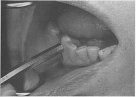
Lingual bar The basic form of a mandibular major connector is a half-pear shape, located above moving tissues but as far below the gingival tissues as possible. It is usually made of reinforced, 6-gauge, half-pear-shaped wax or a similar plastic pattern (Fig. 5-6). The major connector must be contoured so that it does not present sharp margins to the tongue and cause irritation or annoyance by an angular form. The superior border of a lingual bar connector should be tapered toward the gingival tissues superiorly, with its greatest bulk at the inferior border, resulting in a contour that is a half-pear shape. Lingual bar patterns, both wax and plastic, are made in this conventional shape. However, the inferior border of the lingual bar should be slightly rounded when the framework is polished. A rounded border will not impinge on the lingual tissue when the denture bases rotate inferiorly under occlusal loads. Frequently, additional bulk is necessary to provide rigidity, particularly when the bar is long or an alloy of lesser rigidity is used. This is accomplished by underlying the ready-made form with a sheet of 24-gauge casting wax rather than altering the original half-pear shape. The inferior border of a lingual mandibular major connector must be located so that it does not impinge on the tissues in the floor of the mouth as they change elevations during the normal activities of mastication, swallowing, speaking, licking the lips, and so forth. Yet, at the same time it seems logical to locate the inferior border of these connectors as far inferiorly as possible to avoid interference to the resting tongue and trapping of food substances when they are introduced into the mouth. Additionally, the more inferiorly a lingual bar can be located, the farther the superior border of the bar can be placed from the lingual gingival crevices of adjacent teeth, thereby avoiding impingement on the gingival tissues. There are at least two clinically acceptable methods to determine the relative height of the floor of the mouth to locate the inferior border of a lingual mandibular major connector. The first method is to measure the height of the floor of the mouth in relation to the lingual gingival margins of adjacent teeth with a periodontal |
|
|
|
|
|
McCracken's removable partial prosthodontics |
|
A |
|
F |
|
B |
|
c |
|
D |
|
E |
|
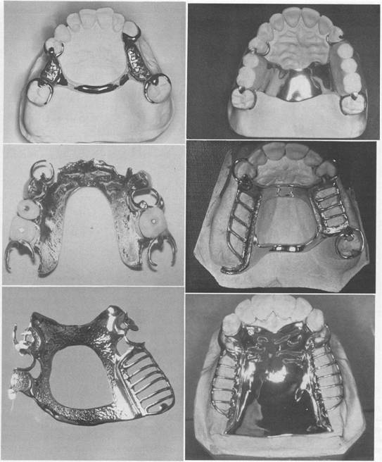
Fig.5-5 A, Lingual bar. B, Sublingual bar. C, Lingual bar with continuous bar (cingulum bar). D, Cingulum bar. E, Linguoplate. F, Labial bar. (C courtesy Dr. Kenneth McHenry SUNY, School of Dental Medicine at Buffalo.) |
|
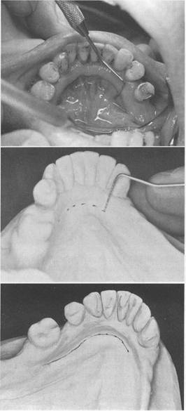
probe (Fig. 5-7). During these measurements the tip of the patient's tongue should be just lightly touching the vermilion border of the upper lip. Recording of these measurements permits their transfer to both diagnostic and master casts, |
|
thus ensuring a rather advantageous location of the inferior border of the major connector. The second method is to use an individualized impression tray having its lingual borders 3 mm short of the elevated floor of the mouth and then to |
|
|
|
|
|
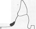
Fig. 5-6 Sagittal section showing half-pear shape of lingual bar. A taper of superior border of the bar to the soft tissues above will minimize interference with tongue and will be more acceptable to the patient than would a dissimilar contour. |
|
use an impression material that will permit the impression to be accurately molded as the patient licks the lips (Fig. 5-8). The inferior border of the planned major connector can then be located at the height of the lingual sulcus of the cast resulting from such an impression. Of the two methods, we have found the measuring of the height of the floor of the mouth to be less variable and more clinically acceptable. A modification of the lingual bar that has been demonstrated to be useful when the height of the floor of the mouth does not allow placement of the superior border of the bar at least 4 mm below the free gingival margin is the sublingual bar. The bar shape remains essentially the same as that of a lingual bar, but placement is inferior and posterior to the usual placement of a lingual bar, lying over and parallel to the anterior floor of the mouth. It is generally accepted that a sublingual bar can be used in lieu of a lingual plate if the lingual frenum does not interfere or in the presence of an anterior lingual undercut that would require considerable blackout for a conventional lingual bar. Contraindications include interfering lingual tori, high attachment of a lingual frenum, and interference to elevation of the floor of the mouth during functional movements. |
|
Cingulum bar (continuous bar) When a linguoplate is the major connector of choice, but the axial alignment of the anterior teeth is such that excessive blockout of interproximal undercuts must be made, a cingulum bar may be considered. A cingulum bar located |
|
Chapter 5 |
|
Major and minor connectors |
|
|
|
A |
|
B |
|
c |
|
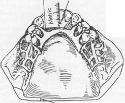
Fig. 5-7 A, Height of floor of mouth (tongue elevated) in relation to lingual gingival sulci measured with a periodontal probe. B, Recorded measurements are transferred to diagnostic cast and then to master cast after mouth preparations are completed. C, Line connecting marks indicates location of inferior border of major connector. If periodontal surgery is performed, line on the cast can be related to incisal edges of teeth and the measurements recorded for subsequent use. |
|
|
|
|
|
42 McCracken's removable partial prosthodontics |
|
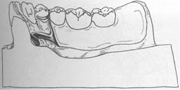
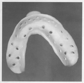
Fig. 5-8 Individualized mandibular acrylic resin impression tray. Lingual flanges should be trimmed so the elevated position of alveolar lingual sulcus can be accurately recorded in impression material when patient touches vermilion border of upper lip with tip of tongue. Tray was fabricated as illustrated in Fig. 15-7. on or slightly above the cingula of the anterior teeth may be added to the lingual bar or can be used independently (Fig. 5-9). Additionally, when wide diastemata exist between the lower anterior teeth, a continuous bar retainer may be more esthetically acceptable than a linguoplate. Linguoplate If the rectangular space bounded by the lingual bar, the continuous bar, and the bordering minor connectors is filled in, a linguoplate results (Figs. 5-10 and 5-11). However, this should only be done for a good reason. The following rule applies: No component of a partial denture should be added arbitrarily or by convention. Each component should be added to serve a definite purpose. The reason for adding a com ponent may be for support, stabilization against |
|
Fig. 5-9 A, Lingual bar and cingulum bar (continuous bar) major connector. Upper portion of this major connector is located on cingula of anterior teeth. Requirement of positive support by rest seats, at least as far anteriorly as the canines, is critical. Note that superior border of lingual bar portion is often placed objectionably close to gingival margins if sufficient bulk for rigidity is to be obtained. This type of major connector is definitely a food trap and is often much more objectionable to patients than a linguoplate from the standpoint of annoyance. B, Cingulum bar (continuous bar) major connector. Although this design may eliminate the possibility of food entrapment, it may not provide adequate rigidity. horizontal rotation, retention, preservation of the health of the tissues, esthetics, patient comfort, or anyone of several other reasons. The dentist alone is responsible for the choice of design used and must have good reasons, both biologic and mechanical, for making these choices. A linguoplate should be made as thin as is technically feasible and should be contoured to follow the contours of the teeth and |
|
|
|
|
|
|
|
|
|
Fig. 5-10 Linguoplate is used when space between bounding connectors is better filled than left open. Such an apron does not serve to replace those connectors but, instead, is added to fundamental denture design to make major connector rigid. |
|
Fig. 5-11 View of mandibular Class II design with contoured linguoplate. Linguoplate is made as thin as possible and follows contours of teeth contacted, resulting in scalloped shape. |
|
embrasures (Fig. 5-12). The patient should be aware of as little added bulk and altered contours as possible. The upper border should follow the natural curvature of the supracingular surfaces of the teeth and should not be located above the middle third of the lingual surface except to cover interproximal spaces to the contact points. The half-pear shape of a lingual bar should still form the inferior border providing the greatest bulk and rigidity. All gingival crevices and deep embrasures must be blocked out parallel to the path of placement to avoid gingival irritation |
|
.Chapter 5 |
|
Major and minor connectors |
|
|
|
Fig.5-12 Apron of linguoplate (tissue side) is closely adapted to teeth extending into nonundercut interproximal embrasures, resulting in scalloped form. This form will use some anterior teeth in group function to help resist horizontal rotational tendencies of the restoration. |
|
Fig. 5-13 If linguoplate major connector was indicated for this patient with overlapped anterior teeth, judicious recontouring of lingual proximal surfaces of right lateral, right central, and left lateral incisors would eliminate excessive undercuts and permit closer adaptation of lingual apron of major connector. |
|
and any wedging effect between the teeth. In many instances the judicious recontouring of lingual proximal surfaces of overlapped anterior teeth permits a closer adaptation of the linguo plate major connector, eliminating otherwise deep interproximal embrasures to be covered (Fig. 5-13). The linguoplate does not in itself serve as an indirect retainer. When indirect retention is required, definite rests must be provided for |
|
|
|
|
|
McCracken's removable partial prosthodontics |
|
this purpose. Both the linguoplate and the cingulum bar should ideally have a terminal rest at each end regardless of the need for indirect retention. However, when indirect retainers are necessary, these rests may also serve as terminal rests for the linguoplate or continuous bar. |
|
Indications for the use of a linguoplate. The indications for the use of a linguoplate may be listed as follows: 1. When the lingual frenum is high or the space available for a lingual bar is limited. In either instance the superior border of a lingual bar would have to be placed too close to the gingival tissues. Irritation could be avoided only by generous relief, which might be annoying to the tongue and create an undesirable food trap. Where a clinical measurement from the free gingival margins to the slightly elevated floor of the mouth is less than 8 mm, a linguopla!e is indicated in lieu of a lingual bar. The use of a linguoplate permits the inferior border to be placed more superiorly without tongue and gingival irritation and without compromise of rigidity. 2. In Class I situations in which the residual ridges have undergone excessive vertical resorption. Flat residual ridges offer little resistance to the horizontal rotational tendencies of a denture. The bracing effect provided by the remaining teeth must be depended on to resist such rotation. A correctly de signed linguoplate will engage the remaining teeth to help resist horizontal rotations (see Fig. 5-10). 3. For stabilizing periodontally weakened teeth. Although not as effective as splinting with restorative materials and not as effective as the addition of a labial bar, splinting with a linguoplate can be of some value when used with definite rests on sound adjacent teeth. A cingulum bar may be used to accomplish the same purpose because it actually represents the superior border of a linguoplate without the gingival apron. The cingulum bar accomplishes stabilization along with the other advantages of a linguoplate; however, it is frequently more objectionable to the patient's tongue and is certainly more of a food |
|
trap than is the contoured apron of a linguoplate. 4. When the future replacement of one or more incisor teeth will be facilitated by the addition of retention loops to an existing linguoplate. Mandibular incisors that are periodontally weak may thus be retained, with provisions for possible loss and future additions. The same reasons for use of a linguoplate anteriorly apply to its use elsewhere in the mandibular arch. If a lingual bar alone is to be used anteriorly, there is no reason for adding an apron elsewhere. However, when auxiliary splinting is used for stabilization of the remaining teeth, for horizontal stabilizing of the prosthesis, or for both, small rectangular spaces sometimes remain. Tissue response to such small spaces is better when bridged with an apron than when it is left open. Generally the apron is used to avoid gingival irritation or entrapment of food debris or to cover generously relieved areas that would be irritating to the tongue (Fig. 5-14). Sometimes a dentist is faced with a clinical situation wherein a linguoplate is indicated as the major connector of choice even though the anterior teeth are quite spaced and the patient strenuously objects to metal showing through the spaces. The linguoplate can then be constructed so that the metal will not apprecia |
|
" |
|
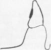
Fig. 5-14 Sagittal section through linguoplate demonstrating basic half-pear-shaped inferior border with metallic apron extending superiorly. Extension of linguoplate to height of contour on premolar was accomplished to enclose a rather large triangular interproximal space inferior to contact point between canine and premolar. Such spaces may often be bridged to eliminate obvious food traps. |
|
|
|
|
|
bly show through the spaced anterior teeth (Fig. 5-15). Ri15idity of the major connector is not greatly altered; however, such a design may be as much of a food trap as the continuous bar type of major connector. |
|
|
|
Fig. 5-15 Interrupted linguoplate in presence of diastemata |
|
A |
|
c |
|
Chapter 5 |
|
Major and minor connectors |
|
|
|
Labial bar |
|
Portunately there are few situations in which extreme lingual inclination of the remaining lower premolar and incisor teeth prevents the use of a lingual bar major connector. By conservative mouth preparations in the form of recontouring and by blockout, a lingual major connector can almost always be used. Lingually inclined teeth may sometimes have to be reshaped by means of crowns. Although the use of a labial major connector may be necessary in rare instances, it should be avoided by resorting to necessary mouth preparations, rather than by accepting a condition that is otherwise correctable (Fig. 5-16). The same applies to the use of a labial bar when a mandibular torus interferes with the placement of a lingual bar. Unless surgery is definitely contraindicated, interfering mandibular tori should be removed so that the use of a labial bar connector may be avoided. A modification to the linguoplate is the hinged continuous labial bar. This concept is |
|
B |
|
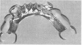
Fig. 5-16 A, Severe lingual inclinations of patient's canines and premolars preclude use of lingual bar. Advanced age of patient and economic status ruled out either orthodontic treatment or fixed restorations. B, Labial bar major connector was used in treatment. C, Retention was obtained on terminal abutments. Support and stabilization were gained by using rests, minor connectors arising from labial bar, and well-fitting denture bases. |
|
|
|
|
|
|
|
|
|
McCracken's removable partial prosthodontics |
|
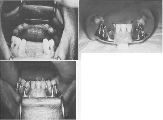
Fig. 5-17 The hinge for this continuous labial bar connector is located at the buccal aspect of left second premolar. Latching mechanism can be seen on buccal flange of the denture, between the right canine and first premolar. |
|
incorporated in the Swing-Lock* design, which consists of a labial or buccal bar that is connected to the major connector by a hinge on one end and a latch at the other end (Fig. 5-17). Support is provided by multiple rests on the remaining natural teeth. Stabilization and reciprocation are provided by a linguoplate contacting the remaining teeth and are supplemented by the labial bar with its retentive struts. Retention is provided by bar-type retentive clasp arms projecting from the labial or buccal bar and contacting the infrabulge areas on the labial surfaces of the teeth. Use of the Swing-Lock concept would seem primarily indicated when the following conditions are present: 1. Missing key abutments. By using all the remaining teeth for retention and stability, the absence of a key abutment (such as a canine) may not present as serious a treatment problem with this concept as with more conventional designs (Fig. 5-18). 2. Unfavorable tooth contours. When existing tooth contours (uncorrectable by recontouring with appropriate restorations) or excessive labial inclinations of anterior teeth prevent conventional clasp designs, the basic |
|
*Swing-Lock, Idea Development Company, Dallas, Tex. |
|
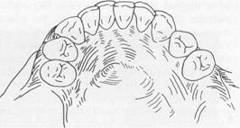
Fig. 5-18 Absence of right canine and lateral incisor (mirror image) requires that all remaining anterior teeth be used for stabilization and retention of replacement restoration. Swing-Lock concept can be used to ensure group function of these remaining mandibular teeth. |
|
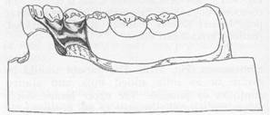
Fig. 5-19 Excessive labial inclinations of anterior teeth cannot be satisfactorily corrected with restorations so that the patient can be provided with a conventional removable partial denture. |
|
principles of removable partial design may be better implemented with the Swing-Lock concept (Fig. 5-19). 3. Unfavorable soft tissue contours. Extensive soft tissue undercuts may prevent proper location of component parts of a conventional removable partial denture or an overdenture |
|
|
|
|
|
|
|
|
|
Fig. 5.20 Excessive labial soft tissue undercuts prevent use of conventional clasping of terminal abutments. One could consider the Swing-Lock design to use all remaining anterior teeth for support, stabilization, and retention. |
|
Fig. 5.21 Mobility of right canine suggests guarded prognosis for its use as terminal abutment. If splinting carmot be accomplished, the patient might be better served with a hinged continuous labial bar in conjunction with a linguoplate major connector. |
|
(Fig. 5-20). The hinged continuous labial bar concept may provide an adjunctive modality to accommodate such unfavorable soft tissue contours. 4. Teeth with questionable prognoses. The possibility of losing a key abutment tooth |
|
Chapter 5 |
|
Major and minor connectors |
|
|
|
Fig. 5-22 Poor oral hygiene and lack of motivation for oral health certainly contribute to limited success of any dental treatment. |
|
with a guarded prognosis seriously affects the stability and retention of a conventional prosthesis (Fig. 5-21). Because all of the remaining teeth function as abutments in the Swing-Lock denture, the loss of a tooth would seemingly not compromise retention and stability to such a degree. The hinged labial bar type of restoration can be used satisfactorily for certain clinically compromised situations. As is true with any type of removable restoration, good oral hygiene, maintenance, and regular recall, as well as close attention to details of design, are paramount to successful implementation of this treatment concept. Obvious contraindications to the use of this hinged labial bar concept are apparent. The most obvious is poor oral hygiene or lack of motivation for plaque control by the patient (Fig. 5-22). Other contraindications are the presence of a shallow buccal or labial vestibule or a high frenal attachment (Fig. 5-23). Any of these factors would prevent the proper placement of components of the Swing-Lock partial denture. Design of mandibular major connectors The following systematic approach to designing mandibular lingual bar and linguoplate major connectors can be readily used with the diagnostic casts after considering the diagnostic data |
|
|
|
McCracken's removable partial prosthodonti, |
|
far enough above the gingival attachment to provide for bridging the gingival crevice with blackout. At the same time, they should be low enough on the tooth to avoid unfavorable leverage and low enough on the maxillary incisors and canine teeth to avoid incisal interference of the opposing dentition. Major connector components resting on unprepared tooth surfaces can lead to slippage of the denture along inclines, to orthodontic movement of the tooth, or to both. In either situation, settling into gingival tissues is inevitable. In the absence of the required vertical support, the health of the surrounding tissues is usually impaired. Similarly, interproximal projections of the major connector that rest on the gingival third of the tooth and on gingiva] tissues that are structurally unable to render support can cause impingement to the detrimenl of the health of those tissues. A cardinal rule for the location of the majOi connector in relation to the remaining teetl1 and to their surrounding gingivae is: Eithel support the major connector by definite rest_ on the teeth contacted, bridging the gingivaE with adequate relief, or locate the connector fal enough away from the gingivae to avoid an) possible restriction of blood supply and en. trapment of food debris. All gingival crossing_ should be abrupt and at right angles to the majOJ connector, and these should bridge the gingiva_ with adequate relief. Creating a sharp, angulaJ form on any portion of a palatal connectOJ should be avoided, and all borders should b_ tapered toward the tissues. Single palatal bar To differentiate between a palatal bar and ( palatal strap, a palatal connector component 0 less than 8 mm in width is referred to as a bar ir this textbook. The single palatal bar is perhap: the most widely used and yet the least logical 0 all palatal major connectors (Fig. 5-26). It i: difficult to say whether the bar or the U-shapec palatal connector is the more objectionable palatal connectors. For a single palatal bar to have the necess, rigidity for cross-arch distribution of stress, must have concentrated bulk, which, unfor natelv. is all too often ignored. For a sin! |
|
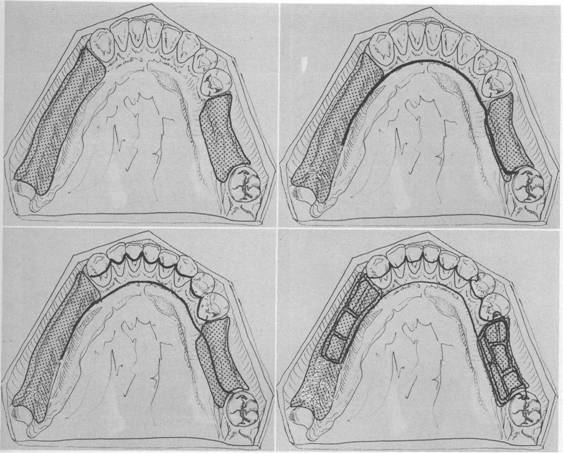
Fig. 5-23 If otherwise indicated, a hinged labial bar could not be optimally located because of shallow labial vestibule. Vestibular depth could be increased by surgical intervention. and relating them to the basic principles of major connector design: Step 1 Outline the basa1 seat areas on the diag nostic cast (Fig. 5-24, A) Step 2 Outline the inferior border of the major connector (Fig. 5-24, B) Step 3 Outline the superior border of the major connector (Fig. 5-24, C) Step 4 Connect the basal seat area to the inferior and superior borders of the major connector, and add minor connectors to retain the acrylic resin denture base material (Fig. 5-24, D) Maxillary major connectors Six basic types of maxillary major connectors are considered: 1. Single palatal bar (Fig. 5-25, A) 2. Single palatal strap (Fig. 5-25, B) 3. U-shaped palatal connector (Fig. 5-25, C) 4. Anterior-posterior palatal bars (Fig. 5-25, D) 5. Combination anterior and posterior palatal strap-type connector (Fig. 5-25, E) 6. Palatal plate-type connector (Fig. 5-25, F) Whenever it is necessary for the palatal connector to make contact with the teeth for reasons of support, definite tooth support must be provided. This is best accomplished by establishing definite rest seats on the predetermined abutment teeth. These should be located |
|
" |
|
|
|
|
|
A |
|
c |
|
Chapter 5 |
|
Major and minor connectors |
|
B |
|
D |
|
Fig. 5-24 A, Diagnostic cast with basal seat areas outlined. H, Inferior border of major COimector is outlined. Location of inferior border was determined as suggested in Fig. 5-7. C, Superior border of major connector is outlined. Limited space for lingual bar requires use of linguoplate major connector. Linguoplate requires that rest seats be used on canines and first premolar for positive support. Lingual space between right canine and premolars is bridged by major connector to enhance its rigidity. D, Rest seat areas on posterior teeth are outlined, and minor connectors for retention of acrylic resin denture bases are sketched. |
|
palatal bar to be effective, it must be rigid enough to provide support and cross-arch stabilization and must be centrally located between the two halves of the denture. Mechanically this practice may be sound enough; however, from the standpoint of patient comfort and alteration of palatal contours, it is highly objectionable. A partial denture made with a single palatal bar is often either too thin and flexible or too |
|
bulky and objectionable to the patient's tongue. The decision to use a single palatal bar instead of a strap should be based on the size of the denture-bearing areas that are connected and on whether a single connector located between them would be rigid without objectionable bulk. Single palatal strap Bilateral tooth-supported restorations, even those with short edentulous spaces, are more |
|
|
|
|
|
McCracken's removable partial prosthodontics |
|
E |
|
B |
|
I II |
|
A |
|
c |
|
D |
|
F |
|
Fig. 5-25 Maxillary major connectors: A, Single palatal bar. B, Single palatal strap-type. C, U-shaped. D, Anterior-posterior palatal bars. E, Anterior-posterior palatal strap-type. F, Palatal plate-type major connector. |
|
|
|
|
|
|
|
Fig. 5-26 Half-round single palatal bar must be bulky to obtain rigidity required for cross-arch distribution of stress. Its bulk may make it objectionable to patient's tongue. |
|
effectively connected with a single, broad palatal strap connector, particularly when the edentulous areas are located posteriorly (Fig. 5-27). Such a connector can be made rigid, without objectionable bulk and interference to the tongue, provided the cast framework material is distributed in three planes. Suitable rigidity, without excessive bulk, may be obtained for a single palatal strap by the laboratory technician casting a 22-gauge matte plastic pattern. For reasons of torque and leverage, a single bar or strap palatal major connector should not be used to connect anterior replacements with distal extension bases. To be rigid enough to resist torque and to provide adequate vertical support and horizontal stabilization, a single bar or strap would have to be objectiombly bulky. When placed anteriorly, this bulk would become even more objectionable to the patient because it could interfere with speech. |
|
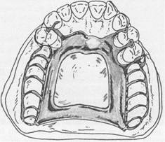
U-shaped palatal connector From both the patient's standpoint and a mechanical standpoint, the U-shaped palatal connector is the least desirable of maxillary major connectors. It should never be used arbitrarily. When a large inoperable palatal torus exists, and occasionally when several anterior teeth are to be replaced, the U-shaped palatal |
|
Chapter 5 |
|
Major and minor connectors |
|
|
|
A |
|
B |
|
Fig. 5-27 A, This single palatal strap-type major connector is better suited for the restoration of short span tooth-supported bilateral edentulous areas. It may also be used in tooth-supported unilateral edentulous situation with provision for cross-arch attachment by either extracoronal retainers or internal attachments. Width of palatal strap should be confined within the boundaries of supporting rests. B, Sagittal section. Midportion of major connector demonstrates slight elevation to provide rigidity. Such thickness of major connector does not appreciably alter palatal contours. |
|
connector may have to be used (Fig. 5-28). In most instances, however, other designs will serve more effectively. The following are the principal objections to use of the U-shaped connector: 1. Its lack of rigidity (compared with other designs) can allow lateral flexure under occlusal forces, which may induce torque or direct lateral force to abutment teeth. 2. The design fails to provide good support characteristics and may permit impingement of underlying tissues when subjected to occlusal loading. |
|
|
|
|
|
|
|
McCracken's removable partial prosthodontics |
|
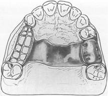
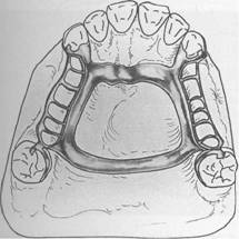
Fig. 5-28 U-shaped palatal connector is probably the least rigid type of maxillary major connector and should be used only when large inoperable palatal torus prevents use of palatal coverage or combination anterior-posterior palatal strap-type designed framework. |
|
3. Bulk to enhance rigidity results in increased thickness in areas that are a hindrance to the tongue. Many maxillary partial dentures have failed for no other reason than the flexibility of a U-shaped major connector (Fig. 5-29). To be rigid, the U-shaped palatal connector must have bulk where the tongue needs the most freedom, which is the rugae area. Without sufficient bulk the U-shaped design leads to increased flexibility and movement at the open ends. In distal extension partial dentures, when tooth support posterior to the edentulous area is nonexistent, movement is particularly noticeable and is traumatic to the residual ridge. No matter how well the extension base is supported or how harmonious the occlusion, without a rigid major connector, the residual ridge suffers. The wider the coverage of a U-shaped major connector, the more it resembles a palatal plate-type connector, with its several advantages. But when used as a narrow U design, the necessary rigidity is usually lacking. AU-shaped connector may be made more rigid by providing multiple tooth support through definite rests. A common error in thc design of aU-shaped connector, however, is its proximity to, or actual |
|
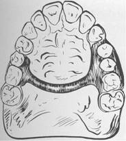
Fig. 5-29 Partial denture design that uses an objectionable U-shaped palatal major connector. Such a connector lacks necessary rigidity, places bulk where it is most objectionable to patient, and impinges on gingival tissue lingual to remaining teeth. This denture failed primarily because it lacked rigidity (in the major connector) and did not provide for indirect retention, occlusal support, and consideration of gingival health in location of anterior border of major connector. |
|
contact with, gingival tissues. The principle that the borders of major connectors should either be supported by rests in prepared rest seats or be located well away from gingival tissues has been stated previously. The majority of U-shaped connectors fail to do either, with resulting gingival irritation and periodontal damage to the tissues adjacent to the remaining teeth. Combination anterior and posterior palatal bar-type connectors Structurally, this combination of major connectors exhibits many of the same disadvantages as the single palatal bar (Fig. 5-30). To be sufficiently rigid and to provide the needed support and stability, these connectors could be too bulky and could interfere with tongue function. |
|
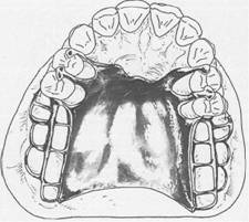
Combination anterior and posterior palatal strap-type connector Structurally, this is a rigid palatal major connector. The anterior and posterior palatal strap combination may be used in almost |
|
|
|
|
|
|
|
a |
|
Fig. 5-30 Combination anterior-posterior palatal bar. To be sufficiently rigid to provide required support and stability, these major connectors must be excessively bulky, which often interferes with the tongue. |
|
any maxillary partial denture design (Figs. 5-31 and 5-32). A posterior palatal strap should be flat and a minimum of 8 mm wide. Posterior palatal connectors should be located as far posteriorly as possible to avoid interference with the tongue, but they should never be placed on moving tissues. The connectors should be located on the hard palate anterior to the line of flexure formed by the junction of the hard and soft palates. The only condition preventing their use is when there is an inoperable maxillary torus that extends posteriorly to the soft palate. In this situation a broad U-shaped major connector may be used. The strength of this major connector design lies in the fact that the anterior and posterior components are joined together by longitudinal connectors on either side, forming a square or rectangular frame. Each component braces the others against possible torque and flexure. Flexure is practically nonexistent in such a design. The anterior connector may be extended anteriorly to support anterior tooth replacements (see Fig. 5-32). In this form aU-shaped connector is made rigid because of the added horizontal strap posteriorly. If a maxillary torus |
|
Chapter 5 |
|
Major and minor connectors |
|
|
|
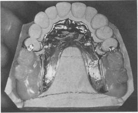
Fig. 5-31 Anterior-posterior palatal strap-type major connector. Anterior component is a flat strap located as far posteriorly as possible to avoid rugae coverage and tongue interference. Anterior border of this strap should be located just posterior to a rugae crest or in the valley between two crests. Posterior strap is thin, a minimum of 8 mm wide, and is located as far posteriorly as possible, yet entirely on hard palate. It should be located at right angles to midline rather than diagonally. |
|
Fig. 5-32 Anterior-posterior component major connector for a Class IV partially edentulous arch. Positive support for anterior portion of major connector is furnished by splint bar joining the four crowned premolars. Notice that the lateral portions of the major connector are placed at least 6 mm from the lingual gingival crevices. |
|
|
|
|
|
|
|
McCracken's removable partial prosthodontics |
|
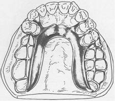
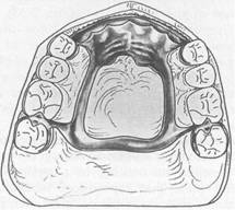
exists, it may be encircled by this type of major strap-type connector without sacrificing rigidity. The combination anterior-posterior connector design may be used with any Kennedy class of partially edentulous arch. It is used most frequently in Classes II and IV, whereas the single wide palatal strap is more frequently used in Class III situations. The palatal plate-type or complete coverage connector is used most frequently in Class I situations for reasons to be explained subsequently. Both anterior and posterior palatal bar and palatal strap connectors, and the anterior and posterior borders of a palatal plate, should cross the midline at a right angle rather than on a diagonal. This is for reasons of symmetry. The tongue, being a bilateral organ, will accept symmetrically placed components far more readily than those placed without regard for bilateral symmetry. Therefore any irregularities in the connector should be placed to one side of the midline so that the connector may pass from one side to the other at -right angles to the sagittal plane. Palatal plate-type connector For the lack of better terminology, the words palatal plate are used to designate any thin, broad, contoured palatal coverage used as a maxillary major connector and covering one half or more of the hard palate (Fig. 5-33). Ana tomic replica palatal castings have uniform thickness and strength by reason of their corrugated contours. Through the use of electrolytic polishing, uniformity of thickness can be maintained, and the anatomic contours of the palate are faithfully reproduced in the finished denture. The anatomic replica palatal major connector has the following several advantages: 1. It permits the making of a uniformly thin metal plate that reproduces faithfully the anatomic contours of the patient's own palate. Its uniform thinness and the thermal conductivity of the metal are designed to make the palatal plate more readily acceptable to the tongue and underlying tissues. 2. The corrugation in the anatomic replica adds strength to the casting; thus a thinner casting with adequate rigidity can be made. |
|
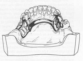
Fig. 5-33 Palatal major connector covering two thirds of palate. Anterior border follows valleys between rugae and does not extend anterior to indirect retainers on first premolars. Posterior border is located at junction of hard and soft palates but does not extend onto soft palate. In bilateral distal extension situation illustrated, indirect retainers are a must to aid in resisting horizontal rotation of the restoration. Note that provisions have been made for a butt-type joint joining the denture bases and framework as denture base on each side passes through pterygomaxillary notch. |
|
3. Surface irregularities are intentional rather than accidental; therefore electrolytic polishing is all that is needed. The original uni form thickness of the plastic pattern is thus maintained. 4. By virtue of intimate contact, interfacial surface tension between metal and tissues provides the prosthesis with greater retention. Retention must be adequate to resist the pull of sticky foods, the action of moving border tissues against the denture, the forces of gravity, and the more violent forces of coughing and sneezing. These are all resisted to some extent by the retention of the base itself, which is proportional to the total area of denture base contact to the supporting tissues. The required amount of both direct and indirect retention will depend on the amount of retention provided by the denture base. |
|