WHY WIND ENERGY?
Wind energy is one of the most promising energy technologies for today, for the 21st century, and beyond.
Wind turbines emit no pollutants.
A modern 600 kW wind turbine in an average location will annually displace 1,200 tones of carbon dioxide from other electricity sources, i.e. usually coal fired power stations. The energy produced by a wind turbine throughout its 20 year life-time (in an average location) is eighty times larger than the amount of energy used to build, maintain, operate, dismantle, and scrapping it again. In other words, on average it takes only two to three months for a wind turbine to recover all the energy required to build and operate it.
The energy in the wind is a truly sustainable resource. Wind will not run out.
Already, wind energy is covering 7 per cent of Danish electricity consumption, a figure that will increase to at least 10 per cent by 2005.
The wind resources above the shallow waters in the seas
around Europe could theoretically provide all of
Wind Turbines have grown dramatically in size and power output.
A typical Danish wind turbine of 1980 vintage had a 26 kW generator and a rotor diameter of 10.5metres. A modern wind turbine has a rotor diameter of 43 meters and a 600 kW generator. It will produce between 1 and 2 million kilowatt hours in a year. This is equivalent to the annual electricity consumption of 300 to 500 European households. The latest generation of wind turbines has a 1,000-1,500 kW generator and a 50-64 meter rotor diameter.
Europe's largest
wind park in Carno,
Wind energy has become the least expensive renewable energy technology in existence.
Today, according to the Danish electrical power companies, the energy cost per kilowatthour of electricity from wind is the same as for new goal fired power stations fitted with smoke scrubbing equipment, i.e. around 0.05 USD per kWh for an average European site.
Wind energy leaves no harmful emissions or residue in the environment. Wind Energy has a proven safety record. Fatal accidents in the wind industry have been related to construction and maintenance work only.
Manufacturers and wind farm developers have by now substantial experience in minimizing the ecological impact of construction work in sensitive areas such as moors, or when building wind farms in offshore locations. Restoring the surrounding landscape to its original state after construction has become a routine task for developers. After the useful life of a wind farm has elapsed, foundations can be reused or removed completely. The scrap value of a wind turbine can normally cover the costs of restoring its site to its initial state. of the year.
WIND TURBINES WHISPER QUIETLY, NOW
Noise is no longer a major problem with advanced wind turbine technology. Modern turbines have far better aerodynamic and mechanical engineering than designs from 10 or 15 years ago, and two-speed generators with slow moving rotors at low wind speeds have done away with the problem of noise at low wind speeds.
At distances above 200 meters, the swishing sound of rotor blades is usually masked completely by wind noise in the leaves of trees or shrubs. The perception of noise is interestingly an extremely subjective phenomenon, and it depends to a large extent on the attitude of the listener:
A Danish scientific survey shows that people who find the sight of wind turbines unpleasant, also perceive that turbines are noisy, regardless of the actual sound level.
WIND ENERGY FITS WELL INTO THE ELECTRICAL GRID
The major drawback of wind power is variability.
In large electrical grids, however, consumers' demand also varies, and electricity generating companies have to keep spare capacity running idle in case a major generating unit breaks down.
If a power company can handle varying consumer demand, it can technically also handle the »negative consumption« from wind turbines. The more wind turbines on the grid, the more short-term fluctuations from one turbine will cancel out the fluctuations from another.
In the Western part of Den-mark, more than 25 per cent of the electricity supply today comes from wind during windy winter nights.
WIND ENERGY IS A SCALEABLE TECHNOLOGY
Wind energy can be used in all sorts of applications - from small battery chargers in lighthouses or remote dwellings to industrial scale turbines capable of supplying the equivalent of the electricity consumption of one thousand families.
Other interesting
and highly economic applications include wind energy combination used in with
diesel powered backup generators in several small, isolated electrical grids
throughout the world. Desalination plants in island communities in the Atlantic
and the
History of windturbines
Poul la Cour (1846-1908) who was originally trained as a meteorologist was the pioneer of modern electricity generating wind turbines.
La Cour was one of the pioneers of modern aerodynamics, and built his own wind tunnel for experiments. La Cour was concerned with the storage of energy, and used the electricity from his wind turbines for electrolysis in order to produce hydrogen for the gas light in his school. One basic drawback of this scheme was the fact that he had to replace the windows of several school buildings several times, as the hydrogen exploded due to small amounts of oxygen in the hydrogen
Two of his test wind turbines in 1897 at
Charles F. Brush (1849-1929) is one of the founders of the American electrical industry.
He invented e.g. a very
efficient DC dynamo used in the public electrical grid, the first commercial
electrical arc light, and an efficient method for manufacturing lead-acid
batteries. His company, Brush Electric in
During the winter of 1887-88 Brush built what is today believed to be
the first automatically operating wind turbine for electricity generation. It was a giant - the
World's largest - with a rotor diameter of 17 m (50 ft.) and 144 rotor blades
made of cedar wood.. ![]() The
turbine ran for 20 years and charged the batteries in the cellar of his
mansion.
The
turbine ran for 20 years and charged the batteries in the cellar of his
mansion. ![]()
Despite the size of the turbine, the generator was only a 12 kW model. This is due to the fact that slowly rotating wind turbines of the American wind rose type do not have a particularly high average efficiency. Brush windmill is particularly noted for its fully automated electrical control system.
Its principles using solenoids does not change very much with future generations of wind turbines - until about 1980 when the wind turbine controllers become equipped with computers.
During World War II the Danish engineering company F.L. Smidth built a number of two- and three-bladed wind turbines.
Danish wind turbine manufacturers have
actually made two-bladed wind turbines, although the so-called "Danish
concept" is a three bladed machine. ![]() All of these machines (like their predecessors) generated DC (direct
current)
All of these machines (like their predecessors) generated DC (direct
current)
Three-bladed F.L. Smidth machine from the
The innovative 200 kW Gedser wind turbine was built in 1956-57 by J. Juul
for the electricity company SEAS at Gedser coast in the Southern part of
The three-bladed upwind turbine with electromechanical yawing and an asynchronous generator was a pioneering design for modern wind turbines, although its rotor with guy wires looks a bit old fashioned today.
The turbine was stall
controlled , and
J. Juul invented the emergency aerodynamic
tip brakes which were released by the centrifugal force in case of over
speed. Basically the same system is used today on modern stall controlled
turbines.![]()
The turbine, which for many years was the world's largest, was incredibly durable. It ran for 11 years without maintenance.
After the first oil crisis
in 1973, interest in wind energy rekindled in several countries. In
In 1979 they built two 630 kW wind turbines, one pitch controlled, and one stall controlled. In many ways they suffered the same fate as their even larger colleagues abroad: The turbines became extremely expensive, and the high energy price subsequently became a key argument against wind energy.
A carpenter, Christian Riisager, however, built a small 22 kW wind turbine in his own back yard using the Gedser Wind Turbine design as a point of departure.
He used inexpensive standard components (e.g. an electric motor as generator, and car parts for gear and mechanical brake) wherever possible.
Riisager's turbine became a
success with many private households around
One important exception to the rule of small machines was the Tvind 2 MW machine, a fairly revolutionary machine. The machine is a downwind machine with 54 m rotor diameter running at variable speed with a synchronous generator, and indirect grid connection using power electronics. The machine is still running nicely.
The Bonus 30 kW machine manufactured from 1980 is an example of one of the early models from present day manufacturers
Nordtank 55 kW![]()
The 55 kW generation of wind turbines, which were developed in-1980 - 1981, became the industrial and technological breakthrough for modern wind turbines.
The cost per kilowatt-hour (kWh) of electricity dropped by about 50 per cent with the appearance of this generation of wind turbines. The wind industry became much more professionalism, and the parallel development of the European Wind Atlas Method by Risoe National Laboratory was extremely important in lowering kWh costs.
![]()
Thousands of machines were delivered
to the wind programme in
Having started series manufacturing of wind turbines about 5 years
earlier, Danish manufacturers had much more of a track record than companies
from other countries. About half of the wind turbines placed in
The market for wind energy
in the
1.3 Offshore Wind Turbines
The Vindeby
windfarm in the Baltic Sea off the coast of
The wind farm consists of 11
Bonus 450 kW stall
controlled wind turbines, and is located between 1.5 and 3 kilometers North
of the coast of the
The turbines were modified to allow room for high voltage transformers inside the turbine towers, and entrance doors are located at a higher level than normally. These same modifications were carried over to the subsequent Tunø Knob project.
Two anemometer masts were placed at the site to study wind conditions, and turbulence, in particular. A number of interesting results on offshore wind conditions have been obtained through these studies which were carried out by Risø National Laboratory
The park has been performing flawlessly. ![]() Electricity production is about 20 per cent higher than on comparable
land sites, although production is somewhat diminished by the wind shade from
the
Electricity production is about 20 per cent higher than on comparable
land sites, although production is somewhat diminished by the wind shade from
the
The Tunø Knob offshore wind farm in
the ![]() The Wind farm consists of 10 Vestas 500 kW pitch controlled wind turbines.
The Wind farm consists of 10 Vestas 500 kW pitch controlled wind turbines.
The turbines were modified for the marine environment, each turbine
being equipped with an electrical crane to be able to replace major parts such
as generators without the need for a floating crane. ![]() In addition, the gearboxes were modified to allow a 10 per cent higher
rotational speed than on the onshore version of the turbine. This will give an additional
electricity production of some 5 per cent. This modification could be carried
out because noise emissions are not a concern with a wind park located 3 kilometers
offshore from the
In addition, the gearboxes were modified to allow a 10 per cent higher
rotational speed than on the onshore version of the turbine. This will give an additional
electricity production of some 5 per cent. This modification could be carried
out because noise emissions are not a concern with a wind park located 3 kilometers
offshore from the
The park has been performing extremely well, and production results have been substantially higher than expected, cf. the page on offshore wind conditions.
The Future of Offshore Wind Energy
Offshore wind energy is an extremely promising application of wind power, particularly in countries with high population density, and thus difficulties in finding suitable sites on land. Construction costs are much higher at sea, but energy production is also much higher
The Danish electricity companies have announced major plans for installation of up to 4 000 megawatts of wind energy offshore in the years after the year 2000. The 4 000 MW of wind power is expected to produce some 13.5 TWh of electricity per year, equivalent to 40 per cent of Danish electricity consumption.
Megawatt-Sized Wind Turbines
The prototype of the NEG Micon 1500 kW Turbine (35K JPEG) was commissioned in September 1995.![]() The original model had a 60 metre rotor diameter and two 750 kW
generators operating in parallel.
The original model had a 60 metre rotor diameter and two 750 kW
generators operating in parallel.
The most recent version is a 1,500/750 kW model (with two 750 kW
generators) with a 64 metre rotor diameter. ![]()
The prototype of the Vestas 1500 kW Turbine) was commissioned in 1996. ![]() The original model had a 63 metre rotor diameter and a 1,500 kW
generator.
The original model had a 63 metre rotor diameter and a 1,500 kW
generator. ![]() The most recent version has a 68 metre rotor diameter and a dual
1650/300 kW generator.
The most recent version has a 68 metre rotor diameter and a dual
1650/300 kW generator.
The Future for Megawatt-Sized Turbines
600 and 750 kW machines continue to be the "working horses" of the industry at present, but the megawatt-market took off in 1998.
Megawatt-sized machines will be ideal for offshore applications, and for areas where space for siting is scarce, so that a megawatt machine will exploit the local wind resources better.
Multi-Megawatt Wind Turbines
NEG Micon 2 MW
The prototype of the NEG Micon 2 MW turbine (1024 x 768 pixels, 132K JPEG) was commissioned in August 1999. It has a 72 m (236 ft.) rotor diameter. In this case it is mounted on a 68-m tower. The turbine is intended for offshore applications.
The difference to 1500 kW NEG Micon machine: The rotor blades are pitchable, since the machine has active stall power control, whereas its 1500 kW cousin has passive stall power control
The prototype of the Bonus 2 MW turbine (88 K) was commissioned in the fall of 1998. It has a 72 m (236 ft.) rotor diameter. The turbine is intended for offshore applications, and has Combi Stall® power control (Bonus trademark for active stall power control). The machine resembles the Bonus 1 MW and 1.3 MW machines considerably
The prototype of the Nordex 2,5 MW turbine (132 K) was commissioned in the spring of 2000. The rotor diameter of the wind turbine is 80 m. which has a 80 m tower. The turbine has pitch power control
Wind Energy Resources
![]()
All renewable energy (except tidal and geothermal power), and even the energy in fossil fuels, ultimately comes from the sun. The sun radiates 174,423,000,000,000-kilowatt hours of energy to the earth per hour. In other words, the earth receives 1.74 x 10¹⁷ watts of power
The power emission from the sun is 1.37 kW/m2 on the surface of the sphere, which has the sun as its centre and the average radius of the earth trajectory. The power hits a circular disc with an area of of 1.27 x 10¹⁴ m2. The power emitted to the earth is thus 1.74 x 10¹⁷W
About 1 to 2 per cent of the energy coming from the sun is converted into wind energy. That is about 50 to 100 times more than the energy converted into biomass by all plants on earth.
On average, plant net primary production is about 4.95 x 10⁶ calories per square metre per year. This is global NPP, Global net primary production, i.e. the amount of energy avai 858q162i lable to all subsequent links in the food/energy chain. The earth's surface area is 5.09 x 10¹⁴ m2. The net power output stored by plants is thus 1.91 x 10¹³W, or 0.011% of the power emitted to earth.
Temperature Differences Drive Air Circulation

The regions around equator, at 0° latitude are heated more by the sun than the rest of the globe. These hot areas are indicated in the warm colours, red, orange and yellow in this infrared picture of sea surface temperatures (taken from a NASA satellite, NOAA-7 in July 1984).
Hot air is lighter than cold air and will rise into the sky until it reaches approximately 10-km (6 miles) altitude and will spread to the North and the South. If the globe did not rotate, the air would simply arrive at the North Pole and the South Pole, sink down, and return to the equator.
The Coriolis Force
Since the globe is rotating, any movement on the Northern hemisphere is diverted to the right, if we look at it from our own position on the ground. (In the southern hemisphere it is bent to the left). This apparent bending force is known as the Coriolis force. (Named after the French mathematician Gustave Gaspard Coriolis 1792-1843).
The Coriolis force to an object's mass (m), its velocity in a rotating frame (vr) and the angular velocity of the rotating frame of reference :
FCoriolis = -2 m (w x vr)
The Coriolis force is a visible phenomenon. Railroad tracks wear out faster on one side than the other. River beds are dug deeper on one side than the other. (Which side depends on which hemisphere we are in: In the Northern hemisphere moving particles are bent towards the right).
In the Northern hemisphere the wind tends to rotate counterclockwise (as seen from above) as it approaches a low pressure area. In the Southern hemisphere the wind rotates clockwise around low pressure areas
How the Coriolis Force Affects Global Winds
The wind rises from the equator and moves north and south in the higher
layers of the atmosphere. Around 30° latitude in both
hemispheres the Coriolis force prevents the air from moving much farther. At this latitude there is a
high pressure area, as the air begins sinking down again. ![]() As the wind rises from the equator there will be a low pressure area
close to ground level attracting winds from the North and South.
As the wind rises from the equator there will be a low pressure area
close to ground level attracting winds from the North and South. ![]() At the Poles, there will be high pressure due to the cooling of the air.
At the Poles, there will be high pressure due to the cooling of the air. ![]() Keeping in mind the bending force of the Coriolis force, we thus have
the following general results for the prevailing wind direction:
Keeping in mind the bending force of the Coriolis force, we thus have
the following general results for the prevailing wind direction:
Prevailing Wind Directions
|
Latitude |
90-60°N |
60-30°N |
30-0°N |
0-30°S |
30-60°S |
60-90°S |
|
Direction |
NE |
SW |
NE |
SE |
NW |
SE |
The size of the atmosphere is grossly exaggerated in the picture above (which was made on a photograph from the NASA GOES-8 satellite). In reality the atmosphere is only 10 km thick, i.e. 1/1200 of the diameter of the globe. That part of the atmosphere is more accurately known as the troposphere. This is where all of our weather (and the greenhouse effect) occurs.
The prevailing wind directions are important when siting wind turbines, since we obviously want to place them in the areas with least obstacles from the prevailing wind directions. Local geography, however, may influence the general results in the table above, cf. the following pages.
Wind
The Atmosphere (Troposphere
The atmosphere around the globe is a very thin layer. The globe has a diameter of 12,000 km. The troposphere, which extends to about 11 km (36,000 ft.) altitude, is where all of our weather, and the greenhouse effect occurs. On the picture you can see at stretch of islands 300 km (200 miles) across, and the approximate height of the troposphere. To look at it at a different scale: If the globe were a ball with a diameter of 1.2 metres (4 ft.), the atmosphere would only be 1 mm (1/25") thick
2.4.2 The Geostrophic Wind
The winds we have
been considering on the previous pages on global winds are
actually the geostrophic winds. The
geostrophic winds are largely driven by temperature differences, and thus
pressure differences, and are not very much influenced by the surface of the
earth. The geostrophic wind is found at altitudes above 1000 metres (3300 ft.)
above ground level. ![]() The
geostrophic wind speed may be measured using weather balloons
The
geostrophic wind speed may be measured using weather balloons
Surface Winds
Winds are very much influenced by the ground surface at altitudes up to
100 metres. The wind will be slowed down by the earth's surface roughness and
obstacles, as
we will learn in a moment. Wind directions near the surface will be slightly
different from the direction of the geostrophic wind because of the earth's
rotation (cf. the Coriolis force ![]() When dealing with wind energy, we are concerned with surface winds, and
how to calculate the usable energy content of the wind
When dealing with wind energy, we are concerned with surface winds, and
how to calculate the usable energy content of the wind
2.4.4 Local Winds: Sea Breezes
Although global winds are
important in determining the prevailing winds in a given area, local climatic
conditions may wield an influence on the most common wind directions. ![]() Local winds are always superimposed upon the larger scale wind systems,
i.e. the wind direction is influenced by the sum of global and local effects.
When larger scale winds are light, local winds may dominate the wind patterns
Local winds are always superimposed upon the larger scale wind systems,
i.e. the wind direction is influenced by the sum of global and local effects.
When larger scale winds are light, local winds may dominate the wind patterns
Land masses are heated by the sun more quickly than the sea in the
daytime. The air rises, flows out to the sea, and creates a low pressure at
ground level which attracts the cool air from the sea. This is called a sea breeze. At nightfall there is often
a period of calm when land and sea temperatures are equal. ![]() At night the wind blows in the opposite direction. The land breeze at night generally has
lower wind speeds, because the temperature difference between land and sea is
smaller at night.
At night the wind blows in the opposite direction. The land breeze at night generally has
lower wind speeds, because the temperature difference between land and sea is
smaller at night.
The monsoon known from South-East Asia is in reality a large-scale form of the sea breeze and land breeze, varying in its direction between seasons, because land masses are heated or cooled more quickly than the sea.
Local Winds: Mountin Winds
Mountain regions display many interesting weather patterns. ![]()
One example is the valley wind
which originates on south-facing slopes (north-facing in the southern
hemisphere). When the slopes and the neighbouring air are heated the density of
the air decreases, and the air ascends towards the top following the surface of
the slope. At night the wind direction is reversed, and turns into a downslope
wind. ![]() If the valley floor is sloped, the air may move down or up the valley,
as a canyon wind.
If the valley floor is sloped, the air may move down or up the valley,
as a canyon wind. ![]() Winds flowing down the leeward sides of mountains can be quite powerful:
Examples are the Foehn in the Alps in Europe, the Chinook in the Rocky
Mountains, and the Zonda in the Andes.
Winds flowing down the leeward sides of mountains can be quite powerful:
Examples are the Foehn in the Alps in Europe, the Chinook in the Rocky
Mountains, and the Zonda in the Andes.
The Energy in the Wind: Air Density and Rotor Area
Density of Air
The kinetic energy of a moving body is proportional to its mass (or weight).
The kinetic energy in the wind thus depends on the density of
the air, i.e. its mass per unit of volume. ![]() In other words, the "heavier" the air, the more energy is
received by the turbine.
In other words, the "heavier" the air, the more energy is
received by the turbine. ![]()
At normal atmospheric pressure and at 15° Celsius air weighs some 1.225 kilogrammes per cubic metre, but the density decreases slightly with increasing humidity. Also, the air is denser when it is cold than when it is warm. At high altitudes, (in mountains) the air pressure is lower, and the air is less dense.
The Ke kinetic energy of an object with total mass M and velocity V:
Ke = ½ *M*V
For determinating the Ke of wind we take a large air parcel this has the geometry of a collection of air molecules passing throught the plane of a wind turbine`s blades.
A- corss sectional area
D- thickness
T- time that is needed for the parcel to pass trough the plane of the wind energy turbine's baldes
Vol- volume of the parcel
Vol = A*D
desity of air in this parcel
ρ = M/Vol
M =.ρ*Vol
V- velocity of the air parcel
T- time required for the parcel to move trought the plane of the wind turbine blades.
V = D/T
D = V*T
Ke = ½ *M*V2
Vol = A*D D = V*T M = *Vol
Ke = ½ * *A*V*T*V2
Ke = ½ * *V3*A*T
Pwr- .power from the air parcel
Pwr = Ke/T = (½ * *V3*A*T)/T
= ½ * *V3*A*
Rotor Area
A typical 600 kW wind turbine has a rotor diameter of 43-44 metres, i.e. a rotor area of some 1,500 square metres. The rotor area determines how much energy a wind turbine is able to harvest from the wind.
Since the rotor area increases with the square of the rotor diameter, a turbine which is twice as large will receive 22 = 2 x 2 = four times as much energy.
A wind turbine rotor converts part of the available wind power into mechanical power and then into electrical power according to:
where
Cp - is the power coefficient,
l is the tip-speed ratio,
w s the wind speed, wr is the rotor speed,
r s the rotor plane radius,
r is the air density,
A is the area swept by the rotor and h(wr ) is the efficiency
of the generator and gear-box.
Pmec is the mechanical power on the
main shaft and
Pel is the electrical power.
The wind turbine rotor, gear-box and generator.
The mechanical power derived from the wind can be described, according to Eq. 1, as a function of the wind speed, w, or as a function of the rotor speed, wr, divided by the tip-speed ratio, l. The measured wind speed is not directly correlated to the mechanical power and therefore averaging procedures have to be used to find the correlation between them [9].
The rotor efficiency curve, Cp(l), is a non-linear function of the tip-speed ratio, l. It is determined by the blade design and the pitch angle and it is sensitive to dirt etc. on the blade surface.
The efficiency of the generator and the gear-box, h(wr), is different for different rotor speeds. At 32 Rpm Eq. 4 becomes
Pmec =Pel*1.12+1.5*1000 (5)
The output power does not only origin from the wind, there will also be an extra power contribution (power from the moment of inertia, Pi) from the system during a deceleration or acceleration of the rotor speed, wr, due to the change of rotational energy Wr, in the rotor.

where J is the rotor inertia, 12500 kgm 2 , Dt is the sample interval
3.3 Wind Turbines Deflect the Wind
Wind turbine will deflect the wind, even before the wind reaches the rotor plane. This means that we will never be able to capture all of the energy in the wind using a wind turbine.
Wind Turbines are limited by what is called the Betz law. If you capture 100% of the energy available in the wind, you stop the wind. The wind will stop flowing through such a turbine. The opposite of that is that if you don't capture any energy in the wind, you don't need a turbine. The wind is able to flow around any major obstruction.
The Betz limit says that essentially, if you capture 59.6% of the energy in the wind, that is the best compromise between stopping the air and forcing it to go around your machine. You need to maintain the flow of air, that's the compromise any wind machine must make whether it is a horizontal axis (traditional style turbine) or vertical axis turbine, with many blades or few, or any such combination. It's covered by the Betz limit.
In the image we have the wind coming from the right, and we use a device to capture part of the kinetic energy in the wind. (In this case we use a three bladed rotor, but it could be some other mechanical device
The Stream Tube
The wind turbine rotor must obviously slow down the wind as it captures its kinetic energy and converts it into rotational energy. This means that the wind will be moving more slowly to the left of the rotor than to the right of the rotor.
Since the amount of air entering through the swept rotor area from the right (every second) must be the same as the amount of air leaving the rotor area to the left, the air will have to occupy a larger cross section (diameter) behind the rotor plane.
In the image above is shown an imaginary tube, a so called stream tube around the wind turbine rotor. The stream tube shows how the slow moving wind to the left in the picture will occupy a large volume behind the rotor.
The wind will not be slowed down to its final speed immediately behind the rotor plane. The slowdown will happen gradually behind the rotor, until the speed becomes almost constant.
As the wind approaches the rotor from the right, the air pressure increases gradually, since the rotor acts as a barrier to the wind. The air pressure will drop immediately behind the rotor plane (to the left). It then gradually increases to the normal air pressure level in the area.
Farther downstream the turbulence in the wind will cause the slow wind behind the rotor to mix with the faster moving wind from the surrounding area. The wind shade behind the rotor will therefore gradually diminish as we move away from the turbine. It is the so called park effect.
Why not a Cylindrical Stream Tube? The wind to the left of the rotor moves with a lower speed than the wind to the right of the rotor. But at the same time we know that the volume of air entering the tube from the right eachsecond must be the same as the volume of air leaving the tube to the left. We can therefore deduce that if we have some obstacle to the wind (in this case our rotor) within the tube, then some of the air coming from the right must be deflected from entering the tube (due to the high air pressure in the right ende of the tube).
The Power of the Wind: Cube of Wind Speed
The wind speed is extremely important for the amount of energy a wind turbine can convert to electricity:
The energy content of the wind varies with the cube (the third power) of the average wind speed, e.g. if the wind speed is twice as high it contains
23 = 2 x 2 x 2 = eight times as much energy.
The acceleration of an object as produced by a net force is directly proportional to the magnitude of the net force, in the same direction as the net force, and inversely proportional to the mass of the object
Fnet = m * a
In the case of the wind turbine we use the energy from braking the wind,
and if we double the wind speed, we
get twice as many slices of wind
moving through the rotor every second, and each of those slices contains four times as much energy, as we
learned from the example of braking a car. The graph shows that at a wind speed
of 8 metres per second we get a power (amount of energy per second) of 314 Watts per square metre exposed to
the wind (the wind is coming from a direction perpendicular to the swept rotor
area). ![]() At 16 m/s we get eight times as much power, i.e. 2509 W/m2.
At 16 m/s we get eight times as much power, i.e. 2509 W/m2.
3.4.1 Power of the Wind Formula
The power of the wind passing perpendicularly through a circular area is:
P= ½ ![]() *v3*
*v3*![]() *r2
*r2
Where
P = the power of the wind measured in W (Watt).
![]() = (rho) = the density of dry air = 1.225 measured in kg/m3
(kilogrammes per cubic metre, at average atmospheric pressure at sea level at
15° C).
= (rho) = the density of dry air = 1.225 measured in kg/m3
(kilogrammes per cubic metre, at average atmospheric pressure at sea level at
15° C).
v = the velocity of the wind measured in m/s (metres per second).
![]() = (pi) = 3.1415926535...
= (pi) = 3.1415926535...
r = the radius (i.e. half the diameter) of the rotor measured in m (metres).
The measurement of wind speeds is usually done using a cup anemometer,
The cup anemometer has a vertical axis and three cups which capture the wind.
The number of revolutions per minute is registered electronically. ![]() Normally, the anemometer is fitted with a wind vane to detect the wind
direction.
Normally, the anemometer is fitted with a wind vane to detect the wind
direction. ![]() Instead of cups, anemometers may be fitted with propellers, although
this is not common.
Instead of cups, anemometers may be fitted with propellers, although
this is not common. ![]() Other anemometer types include ultrasonic or laser anemometers which
detect the phase shifting of sound or coherent light reflected from the air
molecules. Hot wire anemometers detect the wind speed through minute
temperature differences between wires placed in the wind and in the wind shade
(the lee side).
Other anemometer types include ultrasonic or laser anemometers which
detect the phase shifting of sound or coherent light reflected from the air
molecules. Hot wire anemometers detect the wind speed through minute
temperature differences between wires placed in the wind and in the wind shade
(the lee side). ![]() The advantage of non-mechanical anemometers may be that they are less
sensitive to icing. In practice, however, cup anemometers tend to be used everywhere, and
special models with electrically heated shafts and cups may be used in arctic
areas
The advantage of non-mechanical anemometers may be that they are less
sensitive to icing. In practice, however, cup anemometers tend to be used everywhere, and
special models with electrically heated shafts and cups may be used in arctic
areas
Quality Anemometers are a Necessity for Wind Energy Measurement
For
wind speed measurement in the wind energy industry quality of anemometers is
very important. A poorly calibrated anemometer, with measurement errors of
maybe 5 per cent or even 10 per cent.: ![]() if you have an anemometer which
measures wind speeds with a 10% error, you may risk counting on an energy
content of the wind which is 1.13 - 1 = 33% higher than than it is
in reality. If you have to recalculate your measurements to a different wind
turbine hub height (say, from 10 to 50 m height), you may even multiply that
error with a factor of 1.3, thus you end up with a 75% error on your energy
calculation.
if you have an anemometer which
measures wind speeds with a 10% error, you may risk counting on an energy
content of the wind which is 1.13 - 1 = 33% higher than than it is
in reality. If you have to recalculate your measurements to a different wind
turbine hub height (say, from 10 to 50 m height), you may even multiply that
error with a factor of 1.3, thus you end up with a 75% error on your energy
calculation.
![]() The
best way of measuring wind speeds at a prospective wind turbine site is to fit
an anemometer to the top of a mast which has the same height as the expected
hub height of the wind turbine to be used. This way one avoids the uncertainty
involved in recalculating the wind speeds to a different height.
The
best way of measuring wind speeds at a prospective wind turbine site is to fit
an anemometer to the top of a mast which has the same height as the expected
hub height of the wind turbine to be used. This way one avoids the uncertainty
involved in recalculating the wind speeds to a different height.
![]()
![]()
![]() By fitting the anemometer to the top
of the mast one minimises the disturbances of airflows from the mast itself. If
anemometers are placed on the side of the mast it is essential to place them in
the prevailing wind direction in order to minimise the wind shade from the tower.
By fitting the anemometer to the top
of the mast one minimises the disturbances of airflows from the mast itself. If
anemometers are placed on the side of the mast it is essential to place them in
the prevailing wind direction in order to minimise the wind shade from the tower.
Roughness and Wind Shear
High above ground level, at a height of about 1 kilometre, the wind is hardly influenced by the surface of the earth at all. In the lower layers of the atmosphere, however, wind speeds are affected by the friction against the surface of the earth. In the wind industry one distinguishes between the roughness of the terrain, the influence from obstacles, and the influence from the terrain contours, which is also called the orography of the area. We shall be dealing with orography, when we investigate so called speed up effects, i.e. tunnel effects and hill effects, later
Roughness
In general, the more pronounced the roughness of the earth's surface,
the more the wind will be slowed down. ![]() Forests and large cities obviously slow the wind down considerably,
while concrete runways in airports will only slow the wind down a little. Water
surfaces are even smoother than concrete runways, and will have even less
influence on the wind, while long grass and shrubs and bushes will slow the
wind down considerably.
Forests and large cities obviously slow the wind down considerably,
while concrete runways in airports will only slow the wind down a little. Water
surfaces are even smoother than concrete runways, and will have even less
influence on the wind, while long grass and shrubs and bushes will slow the
wind down considerably.
In the wind industry, people usually refer to roughness classes or roughness lengths, when they evaluate wind conditions in a landscape. A high roughness class of 3 to 4 refers to landscapes with many trees and buildings, while a sea surface is in roughness class 0.
Concrete runways in airports are in roughness class 0.5. The same applies to the flat, open landscape to the left which has been grazed by sheep.
The term roughness length is really the distance above ground level where the wind speed theoretically should be zero.
Wind Shear
Wind speeds vary in roughness class 2 (agricultural land with some
houses and sheltering hedgerows with some 500 m intervals), if we assume that
the wind is blowing at 10 m/s at a height of 100 metres. ![]() The fact that the wind profile is twisted towards a lower speed as we
move closer to ground level, is usually called wind shear. Wind shear may also be important when designing wind
turbines. If considered a wind turbine
with a hub height of 40 metres and a rotor diameter of 40 metres, you will
notice that the wind is blowing at 9.3 m/s when the tip of the blade is in its
uppermost position, and only 7.7 m/s when the tip is in the bottom position.
This means that the forces acting on the rotor blade when it is in its top
position are far larger than when it is in its bottom position
The fact that the wind profile is twisted towards a lower speed as we
move closer to ground level, is usually called wind shear. Wind shear may also be important when designing wind
turbines. If considered a wind turbine
with a hub height of 40 metres and a rotor diameter of 40 metres, you will
notice that the wind is blowing at 9.3 m/s when the tip of the blade is in its
uppermost position, and only 7.7 m/s when the tip is in the bottom position.
This means that the forces acting on the rotor blade when it is in its top
position are far larger than when it is in its bottom position
Wind Shear Formula
The wind speed at a certain height above ground level is:
v = vref ln(z/z0) / ln(zref/z0)
v = wind speed at height z above ground level.
vref = reference speed, i.e. a wind speed we already know at height zref.
ln(...) is the natural logarithm function.
z = height above ground level for the desired velocity, v.
z0 = roughness length in the current wind direction. Roughness lengths may be found in the Reference Manual
zref = reference height, i.e. the height where we know the exact wind speed vref.
The formula assumes so-called neutral atmospheric stability conditions, i.e. that the ground surface is neither heated nor cooled compared to the air temperature.
Average wind speeds are often available from meteorological observations
measured at a height of 10 metres. Hub heights of modern 600 to 1,500 kW wind
turbines are usually 40 to 80 metres, however. The spreadsheet will calculate
average wind speeds at different heights and roughness classes. Just enter a
wind speed measured at a certain height for a given roughness class and click
the Submit button. ![]() Please note, that the results are not strictly valid if there are obstacles
close to the wind turbine (or the point of meteorological measurement) at or
above the specified hub height. ["close" means anything up to one
kilometre].
Please note, that the results are not strictly valid if there are obstacles
close to the wind turbine (or the point of meteorological measurement) at or
above the specified hub height. ["close" means anything up to one
kilometre].
That there may be inverse wind
shear on hilltops because of the hill effect,
i.e. the wind speed may actually decline with increasing height during a
certain height interval above the hilltop. You should consult the European Wind
Atlas mentioned in the bibliography in
the Reference Manual for further information on this phenomenon. ![]()
Wind Speed Variability
The wind speed is
always fluctuating, and thus the energy content of the wind is always changing. ![]()
Exactly how large the variation is depends both
on the weather and on local surface conditions and obstacles. ![]()
Energy output from a wind turbine will vary as the wind varies, although the most rapid variations will to some extent be compensated for by the inertia of the wind turbine rotor.
You have probably experienced how hailstorms or thunderstorms in particular, are associated with frequent gusts of wind which both change speed and direction.
In areas with a very uneven terrain surface, and behind obstacles
such as buildings there is similarly created a lot of turbulence, with very irregular wind flows, often in whirls or
vortexes in the neighbourhood. ![]() You can see an example of how turbulence increases the fluctuations in
the wind speed in the image, which you may compare with the image on the
previous page. Turbulence decreases the possibility of using
the energy in the wind effectively for a wind turbine. It also imposes more
tear and wear on the wind turbine, as explained in the section on fatigue loads. Towers for wind turbines are usually made tall enough to avoid
turbulence from the wind close to ground level.
You can see an example of how turbulence increases the fluctuations in
the wind speed in the image, which you may compare with the image on the
previous page. Turbulence decreases the possibility of using
the energy in the wind effectively for a wind turbine. It also imposes more
tear and wear on the wind turbine, as explained in the section on fatigue loads. Towers for wind turbines are usually made tall enough to avoid
turbulence from the wind close to ground level.
4.4 Wind Obstacles
Obstacles to the wind such as buildings, trees, rock formations etc. can decrease wind speeds significantly, and they often create turbulence in their neighborhood. The turbulent zone may extend to some three time the height of the obstacle. The turbulence is more pronounced behind the obstacle than in front of it. Therefore, it is best to avoid major obstacles close to wind turbines, particularly if they are upwind in the prevailing wind direction, i.e. "in front of" the turbine.
4.5 Shelter Behind Obstacles
Obstacles will decrease the wind speed downstream from the obstacle. The decrease in wind speed depends on the porosity of the obstacle, i.e. how "open" the obstacle is. (Porosity is defined as the open area divided by the total area of the object facing the wind).
A building is obviously solid, and has no porosity, whereas a fairly open tree in winter (with no leaves) may let more than half of the wind through. In summer, however, the foliage may be very dense, so as to make the porosity less than, say one third. The slowdown effect on the wind from an obstacle increases with the height and length of the obstacle. The effect is obviously more pronounced close to the obstacle, and close to the ground.
When manufacturers or developers calculate the energy production for wind turbines, they always take obstacles into account if they are close to the turbine - say, less than 1 kilometer away in one of the more important wind directions.
4.6 Turbine Hub Height
The higher you are above the top of the obstacle, the less wind shade. The wind shade, however, may extend to up to five times the height of the obstacle at a certain distance.
If the obstacle is taller than half the hub height, the results are more uncertain, because the detailed geometry of the obstacle,
4.7 Distance Between Obstacle and Turbine
The distance between the obstacle and the turbine is very important for the shelter effect. In general, the shelter effect will decrease as you move away from the obstacle, just like a smoke plume becomes diluted as you move away from a smokestack. In terrain with very low roughness (e.g. water surfaces) the effect of obstacles (e.g. an island) may be measurable up to 20 km away from the obstacle.
If the turbine is closer to the obstacle than five times the obstacle height, the results will be more uncertain, because they will depend on the exact geometry of the obstacle..
4.7 Roughness Length or Roughness Class
The roughness of the terrain between the obstacle and the wind turbine has an important influence on how much the shelter effect is felt. Terrain with low roughness will allow the wind passin outside the obstacle to mix more easily in the wake behind the obstacle, so that it makes the wind shade relatively less important.
4.8 Wake Effec
Since a wind turbine generates electricity from the energy in the wind, the wind leaving the turbine must have a lower energy content than the wind arriving in front of the turbine. This follows directly from the fact that energy can neither be created nor consumed.
Laboratory, Denmark
A wind turbine will always cast a wind shade in the downwind direction. In fact, there will be a wake behind the turbine, i.e. a long trail of wind which is quite turbulent and slowed down, when compared to the wind arriving in front of the turbine. (The expression wake is obviously derived from the wake behind a ship).
You can actually see the wake trailing behind a wind turbine, if you add smoke to the air passing through the turbine, as was done in the picture. (This particular turbine was designed to rotate in a counterclockwis direction which is somewhat unusual for modern wind turbines). Wind turbines in parks are usually spaced at least three rotor diameters from one another in order to avoid too much turbulence around the turbines downstream. In the prevailing wind direction turbines are usually spaced even farther apart.
4.9 Park Effect
Each wind turbine will slow down the wind behind it as it pulls energy out of the wind and converts it to electricity. Ideally, we would therefore like to space turbines as far apart as possible in the prevailing wind direction. On the other hand, land use and the cost of connecting wind turbines to the electrical grid would tell us to space them closer together.
4.10 Speed Up Effects: Tunnel Effect
The air becomes compressed on the windy side of the buildings or mountains, and its speed increases considerably between th obstacles to the wind. This is known as a "tunnel effect". So, even if the general wind speed in open terrain may be, say, 6 metres per second, it can easily reach 9 metres per second in a natural "tunnel".
Placing a wind turbine in such a tunnel is one clever way of obtaining higher wind speeds than in the surrounding areas. To obtain a good tunnel effect the tunnel should be "softly" embedded in the landscape. In case the hills are very rough and uneven, there may be lots of turbulence in the area, i.e. the wind will be whirling in a lot of different (and rapidly changing)
directions.
4.11. Speed Up Effects: Hill Effect
A common way of siting wind turbines is to place them on hills or ridges overlooking the surrounding landscape. In particular, it is always an advantage to have as wide a view as possible in the prevailing wind direction in the area. On hills, one may also experience that wind speeds are higher
than in the surrounding area. Once again, this is due to the fact that the wind becomes compressed on the windy side of the hill, and once the air reaches the ridge it can expand again as its soars down into the low pressure area on the lee side of the hill.
You may notice that the wind in the picture starts bending some time before it reaches the hill, because the high pressure area actually extends quite some distance out in front of the hill. Also, you may notice that the wind becomes very irregular, once it passes through the wind turbine rotor. As before, if the hill is steep or has an uneven surface, one may get significant amounts of turbulence, which may negate the advantage of higher wind speeds.
The General Pattern of Wind Speed Variations
It is very important for the wind industry to be able to describe the variation of wind speeds. Turbine designers need the information to optimise the design of their turbines, so as to minimise generating costs. Turbine investors need the information to estimate their income from electricity.
If you measure wind speeds throughout a year, you will notice that in
most areas strong gale force winds are rare, while moderate and fresh winds are
quite common. ![]() The wind variation for a typical site is usually described using the
so-called Weibull distribution, as
shown in the image. This particular site has a mean wind speed of 7 metres per
second, and the shape of the curve is determined by a so called shape parameter of 2.
The wind variation for a typical site is usually described using the
so-called Weibull distribution, as
shown in the image. This particular site has a mean wind speed of 7 metres per
second, and the shape of the curve is determined by a so called shape parameter of 2.
The Weibull distribution is one of the most commonly
used distributions in reliability engineering because of the many shapes it
attains for various values of ![]() (slope). It can
therefore model a great variety of data and life characteristics [
(slope). It can
therefore model a great variety of data and life characteristics [
The 2-parameter Weibull pdf is given by:
where,
![]()
and,
![]() = scale parameter
= scale parameter
![]() = shape parameter
(or slope).
= shape parameter
(or slope).
5.2 Weibull Statistical Properties Summary
The Mean or MTTF
The
mean ![]() of the 2-parameter
Weibull pdf is given by
of the 2-parameter
Weibull pdf is given by
where ![]() is the gamma function
evaluated at the value of
is the gamma function
evaluated at the value of ![]()
The Median
The
median ![]() of the 2-parameter Weibull
is given by:
of the 2-parameter Weibull
is given by:
![]()
The Mode
The
mode ![]() of the 2-parameter Weibull is given by:
of the 2-parameter Weibull is given by:

The Standard Deviation
The
standard deviation, ![]() of the 2-parameter Weibull is given by
of the 2-parameter Weibull is given by
The cdf and the Reliability Function
The cdf of the 2-parameter Weibull distribution is given by:
The Weibull reliability function is given by:

The Conditional Reliability Function
The Weibull conditional reliability function is given by:
 (8)
(8)
or,
Equation (8) gives the reliability for a new mission of t duration, having already accumulated T hours of operation up to the start of this new mission, and the units are checked out to assure that they will start the next mission successfully. (It is called conditional because you can calculate the reliability of a new mission based on the fact that the unit(s) already accumulated T hours of operation successfully).
The Reliable Life
For the 2-parameter Weibull distribution, the
reliable life, ![]() , of a unit for a
specified reliability, starting the mission at age zero, is given by:
, of a unit for a
specified reliability, starting the mission at age zero, is given by:
![]()
This
is the life for which the unit will function successfully with a reliability of
![]() . If
. If ![]() = 0.50 then
= 0.50 then ![]()
![]() , the median life, or the life by which half of the units will survive.
, the median life, or the life by which half of the units will survive.
The Failure Rate Function
The
2-parameter Weibull failure rate function, ![]() (T), is given by:
(T), is given by:
This subchapter includes the following topics:
Statistical Description of Wind Speeds
The distribution of wind speeds is skewed,
i.e. it is not symmetrical. Sometimes you will have very high wind speeds, but
they are very rare. Wind speeds of 5.5 metres per second, on the other hand,
are the most common ones. 5.5 metres is called the modal value of the distribution. If we multiply each tiny wind
speed interval by the probability of getting that particular wind speed, and
add it all up, we get the mean wind
speed. ![]() The statistical distribution of wind speeds varies from place to place
around the globe, depending upon local climate conditions, the landscape, and
its surface. The Weibull distribution may thus vary, both in its shape, and in
its mean value.
The statistical distribution of wind speeds varies from place to place
around the globe, depending upon local climate conditions, the landscape, and
its surface. The Weibull distribution may thus vary, both in its shape, and in
its mean value. ![]() If the shape parameter is exactly 2, as in the graph on this page, the
distribution is known as a Rayleigh
distribution. Wind turbine manufacturers often give standard performance
figures for their machines using the Rayleigh distribution.
If the shape parameter is exactly 2, as in the graph on this page, the
distribution is known as a Rayleigh
distribution. Wind turbine manufacturers often give standard performance
figures for their machines using the Rayleigh distribution.
Balancing the Weibull Distribution
Another way of finding the mean
wind speed is to balance the pile of blue bricks to the right, which shows
exactly the same as the graph above. Each brick represents the probability that
the wind will be blowing at that speed during 1 per cent of the time during the
year. 1 m/s wind speeds are in the pile to the far left, 17 m/s is to the far
right. ![]() The point at which the whole pile will balance exactly will be at the
7th pile, i.e. the mean wind speed is 7 m/s
The point at which the whole pile will balance exactly will be at the
7th pile, i.e. the mean wind speed is 7 m/s
Mean (Average) Power of the Wind
6.1 Balancing the Power Distribution
The reason why we care about wind speeds is their energy content, just like with the bottles on the previous page: We cared about their content in terms of volume. Now, the volume of a bottle varies with the cube of the size, just like wind power varies with the cube of the wind speed.
6.2 The Ideal Braking of the Wind
Betz' Law
The more kinetic energy a wind turbine pulls out of the wind, the more the wind will be slowed down as it leaves the left side of the turbine in the picture.
If we tried to extract all the energy from the wind, the air would move away with the speed zero, i.e. the air could not leave the turbine. In that case we would not extract any energy at all, since all of the air would obviously also be prevented from entering the rotor of the turbine.
In the other extreme case, the wind could pass though our tube above without being hindered at all. In this case we would likewise not have extracted any energy from the wind.
We can therefore assume that there must be some way of braking the wind, which is in between these two extremes, and is more efficient in converting the energy in the wind to useful mechanical energy. It turns out that there is a surprisingly simple answer to this: An ideal wind turbine would slow down the wind by 2/3 of its original speed.
Models of wind tubines
The possibilities of designing a wind turbine vary from choosing the axis and to the number of blades and orientation of the rotor.
Horizontal Axis Wind Turbines
Most of the technology described on these pages is related to horizontal axis wind turbines (HAWTs, as some people like to call them).
The reason is simple: All grid-connected commercial wind turbines today are built with a propeller-type rotor on a horizontal axis (i.e. a horizontal main shaft). The purpose of the rotor is to convert the linear motion of the wind into rotational energy that can be used to drive a generator. The same basic principle is used in a modern water turbine, where the flow of water is parallel to the rotational axis of the turbine blades.
We distinguish:
Even Number Of Blades ( Wind Rose)
Three-Bladed Concept
Two-Bladed (Teetering) Concept
One-Bladed Concept
1.1. Even Number of Blades
Modern wind turbine engineers avoid building large machines with an even number of rotor blades. The most important reason is the stability of the turbine. A rotor with an odd number of rotor blades (and at least three blades) can be considered to be similar to a disc when calculating the dynamic properties of the machine.
A rotor with an even number of blades will give stability problems for a machine with a stiff structure. The reason is that at the very moment when the uppermost blade bends backwards, because it gets the maximum power from the wind, the lowermost blade passes into the wind shade in front of the tower.
The Danish Three-Bladed Concept
Most modern wind turbines are three-bladed designs with the rotor position maintained upwind (on the windy side of the tower) using electrical motors in their yaw mechanism. This design is usually called the classical Danish concept, and tends to be a standard against which other concepts are evaluated. The vast majority of the turbines sold in world markets have this design. The basic design was first introduced with the renowned Gedser wind turbine. Another characteristic is the use of an asynchronous generator.
7.1.3 Two-Bladed (Teetering) Concept
Two-bladed wind turbine designs have the advantage of saving the cost of one rotor blade and its weight, of course. However, they tend to have difficulty in penetrating the market, partly because they require higher rotational speed to yield the same energy output. This is a disadvantage both in regard to noise and visual intrusion. Lately, several traditional manufacturers of two-bladed machines have switched to three-bladed designs.
Two- and one-bladed machines require a more complex design with a hinged (teetering hub) rotor as shown in the picture, i.e. the rotor has to be able to tilt in order to avoid too heavy shocks to the turbine when a rotor blades passes the tower. The rotor is therefore fitted onto a shaft which is perpendicular to the main shaft, and which rotates along with the main shaft. This arrangement may require additional shock absorbers to prevent the rotor blade from hitting the tower.
7.1.4. One-Bladed Concept
Yes, one-bladed wind turbines do exist, and indeed, they save the cost of another rotor blade! If anything can be built, engineers will do it. One-bladed wind turbines are not very widespread commercially, however, because the same problems that are mentioned under the two-bladed design apply to an even larger extent to one-bladed machines. In addition to higher rotational speed, and the noise and visual intrusion problems, they require a counterweight to be placed on the other side of the hub from the rotor blade in order to balance the rotor. This obviously negates the savings on weight compared to a two-bladed design.
7.1.5. Upwind Machines
Upwind machines have the rotor facing the wind. The basic advantage of upwind designs is that one avoids the wind shade behind the tower. By far the vast majority of wind turbines have this design.
On the other hand, there is also some wind shade in front of the tower, i.e. the wind starts bending away from the tower before it reaches the tower itself, even if the tower is round and smooth.
Therefore, each time the rotor passes the tower, the power from the wind turbine drops slightly. The basic drawback of upwind designs is that the rotor needs to be made rather inflexible, and placed at some distance from the tower (as some manufacturers have found out to their cost). In addition an upwind machine needs a yaw mechanism to keep the rotor facing the wind.
7.1.6. Downwind Machines
Downwind machines have the rotor placed on the lee side of the tower. They have the theoretical advantage that they may be built without a yaw mechanism, if the rotor and nacelle have a suitable design that makes the nacelle follow the wind passively. For large wind turbines this is a somewhat doubtful advantage, however, since you do need cables to lead the current away from the generator. How do you untwist the cables, when the machine has been yawing passively in the same direction for a long period of time, if you do not have a yaw mechanism? (Slip rings or mechanical collectors are not a very good idea if you are working with 1000 ampere currents).
A more important advantage is that the rotor may be made more flexible. This is an advantage both in regard to weight, and the structural dynamics of the machine, i.e. the blades will bend at high wind speeds, thus taking part of the load off the tower.
The basic advantage of the downwind machine is thus, that it may bebuilt somewhat lighter than an upwind machine.
The basic drawback is the fluctuation in the wind power due to the rotor passing through the wind shade of the tower. This may give more fatigue loads on the turbine than with an upwind design.
7.2. Vertical Axes
This category includes wind turbines where the axis direction is at a right angle to the wind direction. In practical terms, this virtually always involves a vertical axis. There is a wonderful bonus from this situation. It works identically well, no matter what direction the wind comes from. So no provision for aiming the mechanism is necessary.
We distinguish:
Savonius Rotor
Darrieus Rotor
7.2.1. Savonius Rotor
An early style is generally called a Savonius Rotor. The spinning part of a weatherman's windspeed device (anemometer) is a Savonius Rotor. Sideways mounted cups catch the wind and cause the vertical shaft to spin. A Savonius Rotor has an advantage over the farm windmill in that it does not have to be pointed into the wind. It works equally well with wind from any direction. However, a Savonius Rotor has a rather low maximum efficiency, around 14%. That efficiency does not drop off as rapidly as most other designs (only the propeller style has a wider range of windspeeds for high efficiency). In addition, the Savonius Rotor has tremendous starting torque where most other designs have very little torque at low rotational velocity.
This design is technically called a low-tip-speed (or slow speed) cross-wind-axis turbine. No airfoil shape is involved, which is part of the explanation for the very low efficiency.
However, the Savonius design is by far the simplest of these various mechanisms. Nearly all of the others involve advanced airfoil shapes and complicated structures. The economy and simplicity of a Savonius Rotor cannot be matched.
7.2.2. Darrieus Rotor
A very sophisticated cross-wind-axis turbine is the Darrieus Rotor. This design looks something like an egg-beater, with usually either two or three curved airfoils.
This design is technically called a high-tip-speed cross-wind-axis turbine. The airfoils and the high airfoil velocities allows this style to have efficiencies as high as about 32%, over a fairly wide range of wind speeds.
The Darrieus machine is characterised by its C-shaped rotor blades which make it look a bit like an eggbeater. It is normally built with two or three blades. The basic theoretical advantages of a vertical axis machine are
1) you may place the generator, gearbox etc. on the ground, and you may not need a tower for the machine.
2) you do not need a yaw mechanism to turn the rotor against the wind.
The basic disadvantages are:
1) Wind speeds are very low close to ground level, so although you may save a tower, your wind speeds will be very low on the lower part of your rotor.
2) The overall efficiency of the vertical axis machines is not impressive.
3) The machine is not self-starting (e.g. a Darrieus machine will need a "push" before it starts. This is only a minor inconvenience for a grid connected turbine, however, since you may use the generator as a motor drawing current from the grid to to start the machine).
4) The machine may need guy wires to hold it up, but guy wires are impractical in heavily farmed areas.
5) Replacing the main bearing for the rotor necessitates removing the rotor on both a horizontal and a vertical axis machine. In the case of the latter, it means tearing the whole machine down. (That is why EOLE 4 in the picture is standing idle).
POWER OUTPUT FROM AN IDEAL TURBINE
The kinetic energy in a parcel of air of mass m ,.owing at speed u in the x direction is:

where A is the cross-sectional area in m2 ,ρ is the air density in kg/m3 ,and x is the thickness of the parcel in m.
If we visualize the parcel as in Fig.1 with side x moving with speed u and the opposite side .xed at the origin, we see the kinetic energy increasing uniformly with x , because the mass is increasing uniformly.
The power in the wind, P w is the time derivative of the kinetic energy:

This can be viewed as the power being supplied at the origin to cause the energy of the parcel to increase according to Eq.1.A wind turbine will extract power from side x ,withEq.2 representing the total power available at this surface for possible extraction.
Figure 1:Packet of air moving with speed u
An expression for air density is given in Chapter 2 and is repeated here for convenience:
In this equation,p is the pressure in kPa and T is the temperature in kelvin.The power in the wind is then:
where A is area in square meters and u is wind speed in meters per second.For air at standard conditions,101.3 kPa and 273 K,this reduces to:
The more general Eq.4 should be used whenever the wind turbine elevation is more than a few hundred meters above sea level or the temperature is signi .cantly above 0 o C.
At standard conditions,the power in 1 m 2 of wind with a speed of 5 m/s is 0.647(5)3 =81 W.The power in the same 1 m 2 of area when the wind speed is 10 m/s is 647 W.
This illustrates two basic features of wind power.One is that wind power is rather di .use.It requires a substantial area of wind turbine to capture a signi .cant amount of power.The other feature is that wind power varies rapidly with wind speed.Overspeed protection devices are therefore required to protect both the turbine and the load at high wind speeds.
The physical presence of a wind turbine in a large moving air mass modi .es the local air speed and pressure.The picture is drawn for a conventional horizontal axis
propeller type turbine.
Consider a tube of moving air with initial or undisturbed diameter d1 speed u1 and pressure p1 as it approaches the turbine. The speed of the air decreases as the turbine is approached, causing the tube of air to enlarge to the turbine diameter d2 The air pressure will rise to a maximum just in front of the turbine and will drop below atmospheric pressure behind the turbine. Part of the kinetic energy in the air is converted to potential energy in order to produce this increase in pressure. Still more kinetic energy will be converted to potential energy after the turbine, in order to raise the air pressure back to atmospheric. This causes the wind speed to continue to decrease until the pressure is in equilibrium. Once the low point of wind speed is reached, the speed of the tube of air will increase back to u4 =u1 as it receives kinetic energy from the surrounding air [3 ].
It can be shown [2 ]that under optimum conditions, when maximum power is being transferred from the tube of air to the turbine, the following relationships hold:
The mechanical power extracted is then the diference between the input and output powerin the wind:
This state that 8/9 of the power in the original tube of air is extracted by an ideal turbine. This tube is smaller than the turbine, however, and this can lead to confusing results. The normal method of expressing this extracted power is in terms of the undisturbed wind speed u1 and the turbine area A2 This method yields
The factor 16/27 =0.593 is sometimes called the Betz coefficient. It shows that an actual turbine cannot extract more than 59.3 percent of the power in an undisturbed tube of air of the same area. In practice, the fraction of power extracted will always be less because of mechanical imperfections. A good fraction is 35-40 percent of the power in the wind under optimum conditions, although fractions as high as 50 percent have been claimed. A turbine which extracts 40 percent of the power in the wind is extracting about two-thirds of the amount that would be extracted by an ideal turbine. This is rather good, considering the aerodynamic problems of constantly changing wind speed and direction as well as the frictional loss due to blade surface roughness.
It is interesting to note that the total pressure difference across the turbine is rather small. For a 6 m/s wind speed, p2 will be about 12.6 Pa greater than p1 while p3 will be about 7.6 Pa less. The pressure difference is then about 0.02 percent of the ambient pressure. Small pressure differences are therefore able to provide rather substantial turbine power outputs
8.1. The Cut In Wind Speed
Usually, wind turbines are designed to start running at wind speeds somewhere around 3 to 5 metres per second. This is called the cut in wind speed. The blue area to the left shows the small amount of power we lose due to the fact the turbine only cuts in after, say 5 m/s.
The Cut Out Wind Speed
The wind turbine will be programmed to stop at high wind speeds above, say 25 metres per second, in order to avoid damaging the turbine or its surroundings. The stop wind speed is called the cut out wind speed. The tiny blue area to the right represents that loss of power
8.3. AERODYNAMICS
Air flow over a stationary airfoil produces two forces, a lift force perpendicular to the air flow and a drag force in the direction of air flow, as shown in Fig.3. The existence of the lift force depends upon laminar flow over the airfoil, which means that the air flows smoothly over both sides of the airfoil. If turbulent flow exists rather than laminar flow, there will be little or no lift force. The air flowing over the top of the airfoil has to speed up because of a greater distance to travel, and this increase in speed causes a slight decrease in pressure. This pressure difference across the airfoil yields the lift force, which is perpendicular to the direction of air flow. The air moving over the airfoil also produces a drag force in the direction of the air flow.
This is a loss term and is minimized as much as possible in high performance wind turbines.
Figure 3:Lift and drag on a stationary airfoil.
Both the lift and the drag are proportional to the air density, the area of the airfoil, and the square of the wind speed.
Suppose now that we allow the airfoil to move in the direction of the lift force. This motion or translation will combine with the motion of the air to produce a relative wind direction shown in Fig.4.The airfoil has been reoriented to maintain a good lift to drag ratio.
The lift is perpendicular to the relative wind but is not in the direction of airfoil translation.
Figure 4:Lift and drag on a translating airfoil.
The lift and drag forces can be split into components parallel and perpendicular to the direction of the undisturbed wind, and these components combined to form the net force F1 in the direction of translation and the net force F2 in the direction of the undisturbed wind. The force F1 is available to do useful work. The force F2 must be used in the design of the airfoil supports to assure structural integrity.
A practical way of using F1 is to connect two such airfoils or blades to a central hub and allow them to rotate around a horizontal axis, as shown in Fig.5. The force F1 causes a torque which drives some load connected to the propeller. The tower must be strong enough to withstand the force F2.
Figure 5:Aerodynamic forces on a turbine blade.
These forces and the overall performance of a wind turbine depend on the construction and orientation of the blades. One important parameter of a blade is the pitch angle, which is the angle between the chord line of the blade and the plane of rotation, as shown in Fig.6. The chord line is the straight line connecting the leading and trailing edges of an airfoil. The plane of rotation is the plane in which the blade tips lie as they rotate. The blade tips actually trace out a circle which lies on the plane of rotation. Full power output would normally be obtained when the wind direction is perpendicular to the plane of rotation. The pitch angle is a static angle, depending only on the orientation of the blade.
Figure 6:Definition of pitch angle β and angle of attack γ
Another important blade parameter is the angle of attack, which is the angle γ between the chord line of the blade and the relative wind or the effective direction of air flow. It is a dynamic angle, depending on both the speed of the blade and the speed of the wind. The blade speed at a distance r from the hub and an angular velocity ωm is rωm A blade with twist will have a variation in angle of attack from hub to tip because of the variation of rωm with distance from the hub. The lift and drag have optimum values for a single angle of attack so a blade without twist is less efficient than a blade with the proper twist to maintain a nearly constant angle of attack from hub to tip. Even the blades of the old Dutch windmills were twisted to improve the efficiency. Most modern blades are twisted, but some are not for cost reasons. A straight blade is easier and cheaper to build and the cost reduction may more than offset the loss in performance.
When the blade is twisted, the pitch angle will change from hub to tip. In this situation, the pitch angle measured three fourths of the distance out from the hub is selected as the refference.
8.4. Annual Energy Output from a Wind Turbine
To calculate the relationship between average wind speeds and annual
energy output from a wind turbine. We will use the default example 600 kW wind
turbine. We have used a standard atmosphere with an air density of 1.225 kg/m3. ![]() For each of the Weibull parameters 1.5, 2.0, and 2.5 we have calculated the annual energy
output for different average wind speeds at turbine hub height.
For each of the Weibull parameters 1.5, 2.0, and 2.5 we have calculated the annual energy
output for different average wind speeds at turbine hub height. ![]() Output may vary up to 50 per cent
depending on the shape parameter at a low average wind speed of 4.5 m/s, while it may vary some 30 per
cent at a very high average wind speed of 10 m/s at hub height
Output may vary up to 50 per cent
depending on the shape parameter at a low average wind speed of 4.5 m/s, while it may vary some 30 per
cent at a very high average wind speed of 10 m/s at hub height
Output varies almost with the
cube of the wind speed. Now, let us look at the red curve with k=2, which is
the curve normally shown by manufacturers: ![]() With an average wind speed of 4.5 m/s at hub height the machine will
generate about 0.5 GWh per year, i.e. 500,000 kWh per year. With an average
wind speed of 9 metres per second it will generate 2.4 GWh/year = 2,400,000 kWh
per year. Thus, doubling the average wind speed has increased energy output 4.8
times.
With an average wind speed of 4.5 m/s at hub height the machine will
generate about 0.5 GWh per year, i.e. 500,000 kWh per year. With an average
wind speed of 9 metres per second it will generate 2.4 GWh/year = 2,400,000 kWh
per year. Thus, doubling the average wind speed has increased energy output 4.8
times. ![]() If we had compared 5 and 10 metres per second instead, we would have
obtained almost exactly 4 times as much energy output.
If we had compared 5 and 10 metres per second instead, we would have
obtained almost exactly 4 times as much energy output. ![]() The reason why we do not obtain exactly the same results in the two
cases, is that the efficiency of the wind turbine varies with the wind speeds.
The reason why we do not obtain exactly the same results in the two
cases, is that the efficiency of the wind turbine varies with the wind speeds.
8.5. The Capacity Factor
Another way of stating the annual energy output from a wind turbine is
to look at the capacity factor for the turbine in its particular location. By
capacity factor we mean its actual annual energy output divided by the
theoretical maximum output, if the machine were running at its rated (maximum)
power during all of the 8766 hours of the year. ![]()
Example: If a 600 kW turbine produces 1.5 million kWh in a year, its capacity factor is = 1500000 : ( 365.25 * 24 * 600 ) = 1500000 : 5259600 = 0.285 = 28.5 per cent. Capacity factors may theoretically vary from 0 to 100 per cent, but in practice they will usually range from 20 to 70 per cent, and mostly be around 25-30 per cent
. Design and Aerodynamic Performance Analysis of 10 kW Horizontal Axis Wind Turbine Rotor Blades
The rotor blades
9.1. The general components of a horizontal axis windturbine are:
nacelle, rotor blades, hub, low speed shaft, gearbox, high speed shaft with its mechanical brake, electrical generator, yaw mechanism, electronic controller, hydraulics system, cooling unit, tower, anemometer and wind vane.
The nacelle contains the key components of the wind turbine, including the gearbox, and the electrical generator. Service personnel may enter the nacelle from the tower of the turbine. To the left of the nacelle we have the wind turbine rotor, i.e. the rotor blades and the hub. It is thought to cover all the mechanisms in order to provide an aerodynamic form outside and to concentrate the wind inside.
The rotor blades capture the wind and transfer its power to the rotor hub. On a modern 600 kW wind turbine each rotor blade measures about 20 meters (66 ft.) in length and is designed much like a wing of an aeroplane.
The hub of the rotor is attached to the low speed shaft of the wind turbine.
The low speed shaft of the wind turbine connects the rotor
hub to the gearbox.
On a modern 600 kW wind turbine the rotor rotates relatively slowly, about 19 to 30.revolutions per minute (RPM). The shaft contains pipes for the hydraulics system to enable the aerodynamic brakes to operate.
The gearbox has the low speed shaft to the left. It makes the high-speed shaft to the right turn approximately 50 times faster than the The high speed shaft rotates with approximately. 1,500 revolutions per minute (RPM) and drives the electrical generator. It is equipped with an emergency mechanical disc brake. The mechanical brake is used in case of failure of the aerodynamic brake, or when the turbine is being serviced.
The electrical generator is usually a so-called induction generator or asynchronous generator. On a modern wind turbine the maximum electric power is usually between 500 and 1,500 kilowatts (kW).
The electronic controller contains a computer, which continuously monitors the condition of the wind turbine and controls the yaw mechanism. In case of any malfunction, (e.g. overheating of the gearbox or the generator), it automatically stops the wind turbine and calls the turbine operator's computer via a telephone modem link.
The hydraulics system is used to reset the aerodynamic brakes of the wind turbine. The cooling unit contains an electric fan, which is used to cool the electrical generator. In addition, it contains an oil-cooling unit, which is used to cool the oil in the gearbox. Some turbines have water-cooled generators.
The tower of the wind turbine carries the nacelle and the rotor. Generally, it is an advantage to have a high tower, since wind speeds increase farther away from the ground. A typical modern 600 kW turbine will have a tower of 40 to 60 metros (132 to 198 ft.) (The height of a 13-20 story building).
Towers may be either tubular towers (such as the one in the picture) or lattice towers. Tubular towers are safer for the personnel that have to maintain the turbines, as they may use an inside ladder to get to the top of the turbine. The advantage of lattice towers is primarily that they are cheaper.
The yaw mechanism uses electrical motors to turn the nacelle with the rotor against the wind. The yaw mechanism is operated by the electronic controller which senses the wind direction using the wind vane. Normally, a turbine will yaw only a few degrees at a time, when the wind changes its direction.
The anemometer and the wind wane are used to measure the speed and the direction of the wind. The electronic signals from the anemometer are used by the wind turbine's electronic controller to start the wind turbine when the wind speed reaches approximately 5 meters per second (10 knots). The computers stop the wind turbine automatically if the wind speed exceeds25 metres per second (50 knots) in order to protect the turbine and its surroundings.
The wind vane signals are used by the wind turbine's electronic controller to turn the wind turbine against the wind, using the yaw mechanism.
9.2. Design and Aerodynamic Performance Analysis of 10 kW Horizontal Axis Wind Turbine Rotor Blades
Design and aerodynamic performance analysis of 10 KW horizontal axis wind turbine (HAWT) rotor blades are carried out. The blade geometry is calculated under consideration that the drag is equal to zero to obtain the optimal blade geometry. Drag effect is included in theoretical performance calculation. The theoretical performance results showed that the maximum power coefficient was 0.46 at tip speed ratio equal to 5.5. This value compared well with available research data. The validation of the theoretical results has been conducted at single low tip speed ratio. The study between theoretical result and experimental measured performance in the torque and power coefficient region for one value of tip speed ratio resulted in good agreement.
A Rotor Area
B Number of Blades
CF Thrust coefficient
CP Power coefficient
CQ Torque coefficient
C Chord
Cl Lift coefficient
Cd Drag Coefficient
h Rotational interference factor
Ma Mach number
k Axial interference factor
P Power
R Rotor radius
R Local blade radius
Re Reynolds number
Rpm Revelation per minuet
VR Rated wind speed (VR = 1.4 - 1.6average wind speed)
Greeks
a Angle of attack
b Twist angle
f Pitch angle
e Drag to lift ratio
l Tip speed ratio
ld Design tip speed ratio
r Density
h Efficiency
d Yaw angle
9.2.1 THEORETICAL ANALYSIS
9.2.1.1 Blade Geometry
Design input data
To design a 10 kW, three-blades fast turning wind turbine rotor, the rated wind speed (VR ) at the site was assumed to be 9 m/s. Three blades ( b ) was used due to its better aerodynamics, structural stability and lower noise emission [5]. The maximum power coefficient and design tip speed ration can be obtained from the fast turning machine Cp -l curve, which can be found in Ref. [7]. The maximum power coefficient (Cp )max was found equal to 0.44 at design tip speed ratio equal to 5.5. The value of CP will vary with change of tip speed ratio ( l
2 Rotor Diameter
The rotor diameter that is required depends upon the power output needed, the wind regime in which it must operate, and the tip speed ratio chosen. Allowance must be made for losses in the generating machine, the transmission system, and all other parts of the drive train. The rotor must therefore develop a good deal more power than outputs of the generator.
Preliminary rotor sizing can be predicated using the elementary actuator disc momentum theory. With drive train efficiency, hd, and a generator efficiency, hg, the actual power output would be
Pout= r ACp hd hg VR 3
Where this expression solved the rotor swept area, A, as
A = p R = 2Pout/r Cp hd hgVR3
Assuming that the wind turbine used has a height of 10m, where the density r=1.224kg/m3 and the generator and train efficiency (hd h g , ) are assumed to be equal to 0.9. The rotor Radius ( R ) is calculated from Eq. (2) and found to be equal to 4.376 m.
3. Selection of the Airfoil
A new airfoil (MEL 002) was selected for the blade rotor. This airfoil was designed by Hikaru Matsumiya for wind power application, since it has the following characteristics:
relatively smooth stall phenomena
higher performance in low Re region
it has the suitable characteristics in the wide Re range from 105 to 106
4 Design steps
Only the equations for the rotor in optimal case (C d = 0) with the
Cl -a curves of the chosen airfoil [8] are required for the calculation of the blade geometry. Glauert presented a blade element analysis to find the ideal blade geometry based on neglecting the airfoil drag but includes wake rotation or swirl.
The equations used in the Glauert idea are the same as those of modified blade element theory [5-7] but with the above assumptions. Therefore the geometry relations can be written as
where c is the local chord, f is the local setting angle, and the values of constants k and h can be obtained from equations except that drag coefficient (C d ) is assumed zero. Those equations are given in a later section.
For the calculation of the blade geometry, a certain number of stations must be taken along the blade and for each station, the chord (c) and setting angle ( f ) have to be calculated. It is assumed that the blade starts at about 0.2R and a good first choice is to take nine stations. The blade design steps are as follows:
Start with r/R = 0.2
Calculate l from Eq. (5)
Calculate k and h from Eqs. (14) and (15)
4. Calculate f from Eq. (3)
5. Obtain a and Cl from MEL002 airfoil graph at (Cl/Cd)max
6. Calculate local b from the velocity diagram [5-7], where b f a
Calculate local chord (C) from Eq. (4)
Select another value of r/R and work again from
step 2 to 8 (r/R = 0.2 to 1.0).
If the chord changes there will be a change in lift coefficient and therefore in a and b . Using linearized chords, these parameters have been calculated again. The new lift coefficient Cl is calculated from Eq. (4).
Theoretical Performance
A frequently used and accurate method for performance calculation for wind turbine rotors is to assume that the flow through the rotor occurs in non-interacting circular stream tubes. This method, when used with the induced velocities, has been called by a variety of names, including modified blade element theory, blade element theory, vortex theory and strip theory. In this method, the locally 2-D flow at each radial station was assumed [5-7], which leads to the following equations:
Where:

The coefficients of performance (power, torque, force coefficients and efficiency ( h )), are not a constant. They varies with the wind speed, the rotation speed of the turbine, turbine blade parameters such as angle of attack, rotor diameter and pitch angle. The rotor geometry has already been determined. One often wants to know what kind of QC vs.l, PC vs. l and h vs.l curves that can be expected from this rotor. The calculation steps using the above equations are as follow:
Start with R/r = 0.2
2. Assume that the value of f is positive value (start with a small value)
Obtain the value of b from Table
4. Calculate the value of a a = f b
At know a , the values of C l and C d can be obtained from the airfoil curves [8]
6. Calculate h , k and E using Eqs. (10), (12) and (13)
7. Calculate a from Eq. (15)
8. Change the value of f , and again work with steps 2 to7.
9. Take other value of r /R , and work again with steps 2 to 8.
A Fortran program based on the above steps had been written and used along with graphical
integration method to obtain the performance parameters,
Maximum power coefficient (CP ) is found to be equal to 0.46 at design tip speed ratio (ad =5.5). Figure (2) showed that the Maximum torque coefficient (CQ ) is found to be equal 0.09 at l equal to 4.8.
3 Rotor in Yaw
The rotor performance parameters as obtained in above section are only valid for the rotor perpendicular to the wind. If the rotor yaws due to the fluctuating of wind direction or to the safety system turning the rotor out of the wind, the rotor performances change.
To predict how they change as a function of the yaw angle, the effective component of the wind must be determined. Using the formula from the section 2.2, the performance parameters can be calculated using the following relations
The results in Fig showed the relationship between yaw angle and maximum power coefficient (CP). The value of CP dropped from 0.46 to 0.41 at yaw angle of 15 deg. and to 0.295 at yaw angle equal to 30 deg.
9.2.3 Experimental Work
3.1 The Rotor Model
The rotor model scale ratio (S.R) depends on the wind tunnel test section, which was used for the test. Scale of 1:12 was chosen to suit the wind tunnel test simulations , which were available in the Mechanical laboratory, University of Heilbronn. The model rotor radius is calculated and found to be equal to 37.5 cm, and all the calculated results which are need to build the model were obtained.
The design of a model rotor presents some difficulties not encountered with the usual wind-tunnel model of an airplane. To begin with, the hub and hinge design and construction can usually be worked out in a satisfactory manner, but some difficulties arise with the rotor blade representation. For most model sizes the built-up blade is not practical, because both of the small size of the skin and twist angle, and also because of the exaggerated effected of the skin wrinkles due to the scale of the model [10].
3.2 Similarity Parameters
According to the similitude theory normally introduced in fluid mechanics [12], all model tests must be conducted under geometric, kinematic, and dynamic similarities [10]. Geometrical similarity requires that the shape of the model must be the same as that of the prototype. Accordingly during the building of the model, great attempt were made to ensure that the model would be similar to the prototype .
Kinematic similarity means the streamline pattern must be similar. According to this condition the wind speed must be as similar for the model as for the prototype. To achieve this condition during the experiment wind speed ranging from 4 to 15m/s at Re range 10 5 - 10 6 (natural Re range) was used. Dynamic similarity means the pressure distribution and the forces
generated by the wind must be similar. Ref. [11] showed that pressure coefficient can be defined by the following relation,
C p y (Re, Ma),
Where y is an arbitrary function.
The above relation shows that the pressure coefficient at any location on a stationary structure is a function of the Re and Ma. However, for a Mach number less than approximately one-third (i.e. for incompressible flow), the effect of Mach number is negligible, and equationreduces to .
Cp = Const*
. RESULTS AND DISCUSSION
The Horizontal Wind Axis Wind Turbine (HWAT) was investigated theoretically and experimentally. The rotor has a radius of R = 4.376 m and was linearly twisted.
The airfoil MEL 002 type was used.
Blade Geometry: The result showed that the rotor have a maximum chord of 0.87 m at r/R of to 0.2 and minimum chord of 0.26 m at the tip with a maximum twist of 19.3
Torque Coefficient (C Q ): maximum CQ of 0.09 was obtained at l of 4.8. The experimental data showed that the torque coefficient of 0.0484 at l of 2.3142 for the rotor.
Power Coefficient (C P ): maximum C P of 0.46 was obtained at l of 5.5. The experimental data showed that the power coefficient of
0.1121 at l of 2.3142 for the rotor.
Efficiency: theoretical efficiency for the rotor was 0.84 at l of 1. It is clear from this result, as the wind speed increases the efficiency decreases, because the energy from wind is proportional with the wind speed. Therefore the ratio of energy extract from the wind to the available energy will decrease, which leads to decreasing of the efficiency.
Effect of Yawing Angle ( d ): The theory and experimental results showed the power and torque coefficients are affected by yawing the rotor The theory showed Cp drop from 0.46 to 0.41 at yaw angle of 15.0 degree and to 0.295 at yaw angle of 30 degree. The maximum C Q , also dropped from 0.09 to 0.084 at yaw angle of 15 degree and to 0.068 at yaw angle of 30 degree. A good agreement was achieved between the theory and experiment at yaw angle of 0,15 and 30 for single low tip speed ratio (l ) value.
9.3. Rotor Aerodynamics
To study how the wind moves relative to the rotor blades of a wind turbine, we have fixed red ribbons to the tip of the rotor blades of our model wind turbine, and yellow ribbons some 1/4 out the length of the blade from the hub. We then let the ribbons float freely in the air (in the cartoon we abstract from the air currents created by the blades themselves, and the centrifugal force).
The two images give you one view from the side of the turbine, and another view from the front of the turbine. Since most wind turbines have constant rotational speed, the speed with which the tip of the rotor blade moves through the air (the tip speed) is typically some 64 m/s, while at the centre of the hub it is zero. 1/4 out the length of the blade, the speed will then be some 16 m/s. The yellow ribbons close to the hub of the rotor will be blown more towards the back of the turbine than the red ribbons at the tips of the blades. This is obviously because at the tip of the blades the speed is some 8 times higher than the speed of thewind hitting the front of the turbine.
Why are Rotor Blades Twisted?
Rotor blades for large wind turbines are always twisted. Seen from the rotor blade, the wind will be coming from a much steeper angle (more from the general wind direction in the landscape), as you move towards the root of the blade, and the centre of the rotor. As you learned on the page on stall, a rotor blade will stop giving lift, if the blade is hit at an angle of attack which is too steep.
Therefore, the rotor blade has to be twisted, so as to acheive anoptimal angle of attack throughout the length of the blade. However, in the case of stall controlled wind turbines in particular, it is important that the blade is built so that it will stall gradually from the blade root and outwards at high wind speeds.
Changing the Wind Speed Changes Wind Direction Relative to the Rotor Blade
In this next picture we have taken one rotor blade from the previous page off its hub, and we look from the hub towards the tip, at the back side (the lee side) of the rotor blade.
The wind in the landscape blows between, say 8 m/s and 16 m/s (from the bottom of the picture), while the tip of the blade rotates towards the left side of the picture. In the picture you can see how the angle of attack of the wind changes much more dramatically at the root of the blade (yellow line) than at the tip of the blade (red line), as the wind changes. If the wind becomes powerful enough to make the blade stall, it will start stalling at the root of the blade.
Lift Direction
Now, let us cut the rotor blade at the point with the yellow line. In the next picture the grey arrow shows the direction of the lift at this point.
The lift is perpendicular to the direction of the wind. As you can see, the lift pulls the blade partly in the direction we want, i.e. to the left. It also bends the rotor blade somewhat, however.
Rotor Blade Profiles (Cross Sections)
As you can see, wind turbine rotor blades look a lot like the wings of an aircraft. In fact, rotor blade designers often use classical aircraft wing profiles as cross sections in the outermost part of the blade. The thick profiles in the innermost part of the blade, however, are usually designed specifically for wind turbines. Choosing profiles for rotor blades involves a number of compromises including reliable lift and stall characteristics, and the profile's ability to perform well even if there is some dirt on the surface (which may be a problem in areas where there is little rain).
Rotor Blade Materials
Most modern rotor blades on large wind turbines are made of glass fibre reinforced plastics, (GRP), i.e. glass fibre reinforced polyester or epoxy.
Using carbon fibre or aramid (Kevlar) as reinforcing material is another possibility, but usually such blades are uneconomic for large turbines. Wood, wood-epoxy, or wood-fibre-epoxy composites have not penetrated the market for rotor blades, although there is still development going on in this area. Steel and aluminium alloys have problems of weight and metal fatigue respectively. They are currently only used for very small wind turbines.
9.4. The Hub
The hub must be large enought to pick up where the blades are no longer able to carry the load. As the radius is reduced and the center of the hub approached, the reduction in the speed of the blade section reduces the potential work which may be accomplished by the blade and increases the mean blade angle. Blade with will begin to increase abnormally and the blade angle will rise sharply until additional with and angle, are no longer practical. At this point the hub must begin..
The hub serves two major aerodinamic purposes. It allows termination of the blades at a point where they would cease to function efficiently and it prevents back flow of air through the center.
If the hub is too large for the required performance, the result will be an increase in velocity pressure, due to the smaller net opening and subsequent waste of power. If the hub is too small the result will be deteriorating of the flow near the hub, possibly even reversal of flow in this area.
The hub must serve also a structural function in connecting the blades and imparting rotation to them.
The nominal power of the wind turbine is directly related to the driving torque, which is determined by the speed and amount of air that passes the rotor. So increasing the size of the turbines has a direct impact on the performance of the wind turbines.
· Increased hub heights brings the rotor in air layers with higher wind speeds
· Increased rotor diameters catch more wind
However not only the torque increases, all loads on all components, from blade tip to tower foundation, increase and many of these components are entering a critical range of allowable stresses and deformations. The hub is one of the most critical components of a wind turbine, especially for larger sizes.
Current design techniques do not suffice anymore for the multi-MW range. Simply up-scaling of the existing designs and adjusting them to meet the specifications leads to designs that are too heavy for production and operation (see ref. [8]). The design of these components is far from optimal. Having non optimised components also has an impact on other components. These will also be heavier than actually required.
Traditional ways of designing and optimizing components will result in solutions that are more or less a parametrical variant of the existing designs. These methods are therefore unable to find solutions, which deviate from the state of the art designs. In order to come to new designs methods should be used which are based on the concept of 'form follows function'. One of these methods is topological optimization. Mecal has used this new approach to develop a hub concept for multi-MW wind turbines.
9.4.1. Designing a hub
According to compared studies and the dimensions of the hub have to be at about 15 % of the rotor diameter. Considering the rotor diameter calculate above D = 8.5 m this results a hub diameter of 1.2 m .
Boundary conditions and loads
In the optimization boundary conditions and loads have to be used, which are similar to those that will be used in a real hub calculation. the size of the blade bearings and main shaft is determined using extrapolation of existing data. In Table 1 the equivalent loads for the flap and edge moment at the blade root as used are listed.
Table 1: Equivalent loads [kNm], N = 5e6
Some geometrical data of attached components are listed in Table 2.
Table 2: Geometrical data of 10 kW hub

Optimisation
In order to allow as much solutions as possible, the definition of the starting volume for the hub is chosen as a solid prism. Since a very large reduction (>95%) has to be achieved, in subsequent runs the starting volume is adjusted in accordance to the optimization results. Decreasing the starting volume increases the accuracy level that can be achieved with a similar effort.
In Figure 3 the final starting volume of the optimization process are displayed
Figure 3: Starting volume for final run
In order to simplify the calculation, the optimization is executed using only the dominant loads, being the tilt and torque moment (Mx and My). Two separate optimization runs are performed for Mx and My, each resulting in a compliance. Additionally an optimization run is performed with both loads applied to the hub, weighted with their compliance, according to
With:
wI Weight factor for load case i [-]
CI Compliance for load case i [N*m]
The result of this combined optimization run is displayed in Figure 4.
Figure 4: Optimization result (elements with h
These results are then translated into a real model.
Real model
The definition of the real model is mainly based on reduced volume that is obtained in the topological optimization. However, geometrical details like fillets and thickness cannot be obtained directly from a shape optimization. Therefore engineering skills are required taking into account other aspects of concern like:
· Castability (small wall thickness are preferred in order to keep cooling time within limits).
· Cast quality that can be achieved at specific locations.
· Accessibility (installation and maintenance).
Strength assessment
Finally a strength assessment is performed on the real model. Stress Reserve Factors for fatigue (SRFf) are calculated. Assuming a low cast quality for the whole hub. This means that no extensive and therefore expensive inspections have to be performed.
Results
In this chapter the results from the optimization and strength assessment are described.
Using the topological optimization a hub is developed. The hub is unlike any other hub that is currently available from any wind turbine manufacturer. The hub basically consists of four main parts
· Inner tube
· Large conical plates at blade bearings
· Connection blade bearings to rear end of tube
· Connection blade bearings to front end of tube
In order to avoid stress peaks at the transitions of each of these components the geometry is smoothened. The final geometry of the optimised hub is displayed in Figure 5.
View at main shaft side View at 'man hole side'
Figure 5: Optimised hub shape
Concept hub vs. traditional hubs
The differences with a traditional hub are obvious:
· The inner tube connects the front and rear part of the hub, in addition to the existing outer shell
· There is no direct connection between the blades
· Large conical plates bring support to the blade bearings
Due to these differences with the traditional hub types the stress distribution due to the dominant loads is improved significantly. The inner tube brings additional stiffness. The large plates suppress local deformations at the blade bearings as well as ovalising of the bearings. This is not only beneficial for the hub but also for the blade connection.
Pitch plates
Traditional hubs using an electrical pitching system tend to have the most critical spots near the pitch motor connection plates. Without these plates, traditional hubs could be less heavy. The multi-MW concept hub uses large conical plates, which not only suppress deformations of the bearings and the hub, but also allow for the connection of pitch motors and other components
Strength assessment
The Stress Reserve Factors for fatigue have been calculated according to the Germanischer Lloyd's 'Rules and regulations' (ref. [1]). The assessment is executed for the whole hub using a hot spot selection routine (see ref. [5]). The results of this routine (a plot of the Stress Reserve Factors for fatigue) are displayed in Figure 6
View at main shaft side View at 'man hole side'
Figure 6: SRF's for fatigue strength
9.5. Wind Turbine Tower
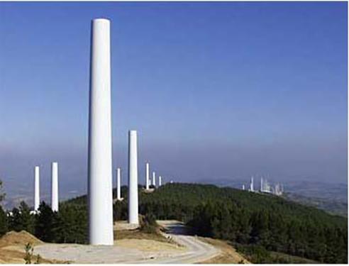
The tower of the wind turbine carries the nacelle and the rotor. Towers for large wind turbines may be either tubular steel towers, lattice towers, or concrete towers. Guyed tubular towers are only used for small wind turbines (battery chargers etc.)
Tubular Steel Towers
Most large wind turbines are delivered with tubular steel towers, which are manufactured in sections of 20-30 meters with flanges at either end, and bolted together on the site. The towers are conical (i.e. with their diameter increasing towards the base) in order to increase their strength and to save materials at the same time.
Lattice Towers
Lattice towers are manufactured using welded steel profiles. The basic advantage of lattice towers is cost, since a lattice tower requires only half as much material as a freely standing tubular tower with a similar stiffness. The basic disadvantage of lattice towers is their visual appearance, (although that issue is clearly debatable). Be that as it may, for aesthetic reasons lattice towers have almost disappeared from use for large, modern wind turbines.
Guyed Pole Towers
Many small wind turbines are built with narrow pole towers supported
by guy wires. The advantage is weight savings, and thus cost. The disadvantages are difficult access around the towers which make them less suitable in farm areas. Finally, this type of tower is more prone to vandalism, thus compromising overall safety.
Hybrid Tower Solutions
Some towers are made in different combinations of the techniques mentioned above. One example is the three-legged Bonus 95 kW tower which you see in the photograph, which may be said to be a hybrid between a lattice tower and a guyed tower.
Aerodynamic Considerations
Generally, it is an advantage to have a tall tower in areas with high terrain roughness, since the wind speeds increases farther away from the ground, as we learned on the page about wind shear.
Lattice towers and guyed pole towers have the advantage of giving less wind shade than a massive tower.
Structural Dynamic Considerations
The rotor blades on turbines with relatively short towers will be subject to very different wind speeds (and thus different bending) when a rotor blade is in its top and in its bottom position, which will increase the fatigue loads on the turbine
Choosing the Tower
Tower height : 14m. This value was choosen after a comparasion study of already builded wind turbines taking in consideration all the aspects mentioned above.
9.6. Power Control of Wind Turbines
Wind turbines are designed to produce electrical energy as cheaply as possible. Wind turbines are therefore generally designed so that they yield maximum output at wind speeds around 15 meters per second. (30 knots or 33 mph). Its does not pay to design turbines that maximize their output at stronger winds, because such strong winds are rare. In case of stronger winds it is necessary to waste part of the excess energy of the wind in order to avoid damaging the wind turbine. All wind turbines are therefore designed with some sort of power control. There are two different ways of doing this safely on modern wind turbines.
9.6.1. Pitch Controlled Wind Turbines
On a pitch controlled wind turbine the turbine's electronic controller checks the power output of the turbine several times per second. When the power output becomes too high, it sends an order to the blade pitch mechanism, which immediately pitches (turns), the rotor blades slightly out of the wind. Conversely, the blades are turned back into the wind whenever the wind drops again.
The rotor blades thus have to be able to turn around their longitudinal axis (to pitch) as shown in the picture.
Note, that the picture is exaggerated:
During normal operation the blades will pitch a fraction of a degree at a time - and the rotor will be turning at the same time. Designing a pitch controlled wind turbine requires some clever engineering to make sure that the rotor blades pitch exactly the amount required. On a pitch controlled wind turbine, the computer will generally pitch the blades a few degrees every time the wind changes in order to keep the rotor blades at the optimum angle in order to maximise output for all wind speeds. The pitch mechanism is usually operated using hydraulics.
![]()
When the wind speed is to fast, to protect the generator the rotor will pitch back and take the rotor area out of the wind. When the excessive wind subsides a spring will pull the rotor back down to normal operating position.
9.6.2. Stall Controlled Wind Turbines
(Passive) stall controlled wind turbines have the rotor blades bolted onto the hub at a fixed angle. The geometry of the rotor blade profile, however has been aerodynamically designed to ensure that the moment the wind speed becomes too high, it creates turbulence on the side of the rotor blade which is not facing the wind as shown in the picture on the previous page. This stall prevents the lifting force of the rotor blade from acting on the rotor. If you have read the section on aerodynamics and aerodynamics and stall, you will realize that as the actual wind speed in the area increases, the angle of attack of the rotor blade will increase, until at some point it starts to stall.
If you look closely at a rotor blade for a stall controlled wind turbine you will notice that the blade is twisted slightly as you move along its longitudinal axis. This is partly done in order to ensure that the rotor blade stalls gradually rather than abruptly when the wind speed reaches its critical value. (Other reasons for twisting the blade are mentioned in the previous section on aerodynamics).
The basic advantage of stall control is that one avoids moving parts in the rotor itself, and a complex control system. On the other hand, stall control represents a very complex aerodynamic design problem, and related design challenges in the structural dynamics of the whole wind turbine, e.g. to avoid stall-induced vibrations. Around two thirds of the wind turbines currently being installed in the world are stall controlled machines.
9.6.3. Active Stall Controlled Wind Turbines
An increasing number of larger wind turbines (1 MW and up) are being developed with an active stall power control mechanism. Technically the active stall machines resemble pitch-controlled machines, since they have pitchable blades. In order to get a reasonably large torque (turning force) at low wind speeds, the machines will usually be programmed to pitch their blades much like a pitch controlled machine at low wind speeds. (Often they use only a few fixed steps depending upon the wind speed). When the machine reaches its rated power, however, you will notice an important difference from the pitch controlled machines: If the generator is about to be overloaded, the machine will pitch its blades in the opposite direction from what a pitch controlled machine does. In other words, it will increase the angle of attack of the rotor blades in order to make the blades go into a deeper stall, thus wasting the excess energy in the wind.
One of the advantages of active stall is that one can control the power output more accurately than with passive stall, so as to avoid overshooting the rated power of the machine at the beginning of a gust of wind. Another advantage is that the machine can be run almost exactly at rated power at all high wind speeds. A normal passive stall controlled wind turbine will usually have a drop in the electrical power output for higher wind speeds, as the rotor blades go into deeper stall.
The pitch mechanism is usually operated using hydraulics or
electric stepper motors. As with pitch control it is largely an economic question whether it is worthwhile to pay for the added complexity of the machine, when the blade pitch mechanism is added.
9.6.4. Other Power Control Methods
Some older wind turbines use ailerons (flaps) to control the power of the rotor, just like aircraft use flaps to alter the geometry of the wings to provide extra lift at takeoff.
Another theoretical possibility is to yaw the rotor partly out of the wind to decrease power. This technique of yaw control is in practice used only for tiny wind turbines (1 kW or less), as it subjects the rotor to cyclically varying stress which may ultimately damage the entire structure.
9.7. The Wind Turbine Yaw Mechanism
The wind turbine yaw mechanism is used to turn the wind turbine rotor against the wind.
Yaw Error
The wind turbine is said to have a yaw error, if the rotor is not perpendicular to the wind. A yaw error implies that a lower share of the energy in the wind will be running through the rotor area. (The share will drop to the cosine of the yaw error, for those of you who know math). If this were the only thing that happened, then yaw control would be an excellent way of controlling the power input to the wind turbine rotor.
That part of the rotor which is closest to the source direction of the wind, however, will be subject to a larger force (bending torque) than the rest of the rotor. On the one hand, this means that the rotor will have a tendency to yaw against the wind automatically, regardless of whether we are dealing with an upwind or a downwind turbine.
On the other hand, it means that the blades will be bending back and forth in a flapwise direction for each turn of the rotor. Wind turbines which are running with a yaw error are therefore subject to larger fatigue loads than wind turbines which are yawed in a perpendicular direction against the wind.
gWind Turbine Generators
The wind turbine generator converts mechanical energy to electrical energy.
Wind turbine generators are a bit unusual, compared to other generating units you ordinarily find attached to the electrical grid. One reason is that the generator has to work with a power source (the wind turbine rotor) which supplies very fluctuating mechanical power (torque).
9.8.1. Cooling System
Generators need cooling while they work. On most turbines this is accomplished by encapsulating the generator in a duct, using a large fan for air cooling, but a few manufacturers use water cooled generators. Water cooled generators may be built more compactly, which also gives some electrical efficiency advantages, but they require a radiator in the nacelle to get rid of the heat from the liquid cooling system.
9.8.2. Starting and Stopping the Generator
If you connected (or disconnected) a large wind turbine generator to the grid by flicking an ordinary switch, you would be quite likely to damage both the generator, the gearbox and the current in the grid in the neighbourhood.
9.8.3. Design Choices in Generators and Grid
Connection
Wind turbines may be designed with either synchronous or asynchronous generators, and with various forms of direct or indirect grid connection of the generator.
Direct grid connection mean that the generator is connected directly to the (usually 3-phase) alternating current grid. Indirect grid connection means that the current from the turbine passes through a series of electric devices which adjust the current to match that of the grid. With an asynchronous generator this occurs automatically.
![]()
3-Phase Generator (or Motor) Principles
All 3-phase generators (or
motors) use a rotating magnetic field. ![]() In the picture to the left we have installed three
electromagnets around a circle. Each of the three magnets is connected to its
own phase in the three phase electrical
grid
In the picture to the left we have installed three
electromagnets around a circle. Each of the three magnets is connected to its
own phase in the three phase electrical
grid ![]() As you can see, each of the three electromagnets alternate between producing a South pole and a North
pole towards the centre. The letters are shown in black when the magnetism is
strong, and in light grey when the magnetism is weak. The fluctuation in
magnetism corresponds exactly to the fluctuation in voltage of each phase. When
one phase is at its peak, the other two have the current running in the
opposite direction, at half the voltage. Since the timing of current in the
three magnets is one third of a cycle apart, the magnetic field will make one
complete revolution per cycle
As you can see, each of the three electromagnets alternate between producing a South pole and a North
pole towards the centre. The letters are shown in black when the magnetism is
strong, and in light grey when the magnetism is weak. The fluctuation in
magnetism corresponds exactly to the fluctuation in voltage of each phase. When
one phase is at its peak, the other two have the current running in the
opposite direction, at half the voltage. Since the timing of current in the
three magnets is one third of a cycle apart, the magnetic field will make one
complete revolution per cycle
Synchronous Motor Operation
The compass needle (with the North pole painted red) will follow the magnetic field exactly, and make one revolution per cycle. With a 50 Hz grid, the needle will make 50 revolutions per second, i.e. 50 times 60 = 3000 rpm (revolutions per minute).
In the picture above, we have in fact managed to build what is called a 2-pole permanent magnet synchronous motor. The reason why it is called a synchronous motor, is that the magnet in the centre will rotate at a constant speed which is synchronous with (running exactly like the cycle in) the rotation of the magnetic field.
The reason why it is called a 2-pole motor is that it has one North and one South pole. It may look like three poles to you, but in fact the compass needle feels the pull from the sum of the magnetic fields around its own magnetic field. So, if the magnet at the top is a strong South pole, the two magnets at the bottom will add up to a strong North pole.
The reason why it is called a permanent magnet motor is that the compass needle in the centre is a permanent magnet, not an electromagnet. (You could make a real motor by replacing the compass needle by a powerful permanent magnet, or an electromagnet which maintains its magnetism through a coil (wound around an iron core) which is fed with direct current).
The setup with the three electromagnets is called the stator in the motor, because this part of the motor remains static (in the same place). The compass needle in the centre is called the rotor, obviously because it rotates.
Synchronous Generator Operation
If you start forcing the magnet around (instead of letting the current from the grid move it), you will discover that it works like a generator, sending alternating current back into the grid. (You should have a more powerful magnet to produce much electricity). The more force (torque) you apply, the more electricity you generate, but the generator will still run at the same speed dictated by the frequency of the electrical grid.
You may disconnect the generator completely from the grid, and start your own private 3-phase electricity grid, hooking your lamps up to the three coils around the electromagnets. (Remember the principle of magnetic / electrical induction from the reference manual section of this web site). If you disconnect the generator from the main grid, however, you will have to crank it at a constant rotational speed in order to produce alternating current with a constant frequency. Consequently, with this type of generator you will normally want to use an indirect grid connection of the generator.
In practice, permanent magnet synchronous generators are not used very much. There are several reasons for this. One reason is that permanent magnets tend to become demagnetised by working in the powerful magnetic fields inside a generator. Another reason is that powerful magnets (made of rare earth metals, e.g. Neodynium) are quite expensive, even if prices have dropped lately
Wind Turbines With Synchronous Generators
Wind turbines which use synchronous generators normally use electromagnets in the rotor which are fed by direct current from the electrical grid. Since the grid supplies alternating current, they first have to convert alternating current to direct current before sending it into the coil windings around the electromagnets in the rotor.
The rotor electromagnets are connected to the current by using brushes and slip rings on the axle (shaft) of the generator
![]()
A Four Pole Generator A Four Pole Generator
The speed of a generator (or motor) which is directly
connected to a three-phase grid is constant, and dictated by the frequency of the
grid If you double the number of magnets in the stator, however, you can ensure that the magnetic field
rotates at half the speed. ![]() In the picture to the left, you see how the magnetic
field now moves clockwise for half a
revolution before it reaches the same magnetic pole as before. We have simply
connected the six magnets to the three phases in a clockwise order.
In the picture to the left, you see how the magnetic
field now moves clockwise for half a
revolution before it reaches the same magnetic pole as before. We have simply
connected the six magnets to the three phases in a clockwise order. ![]() This generator (or motor) has four poles at all times, two South and two North. Since a four pole
generator will only take half a revolution per cycle, it will obviously make 25
revolutions per second on a 50 Hz grid, or 1500 revolutions per minute (rpm).
This generator (or motor) has four poles at all times, two South and two North. Since a four pole
generator will only take half a revolution per cycle, it will obviously make 25
revolutions per second on a 50 Hz grid, or 1500 revolutions per minute (rpm). ![]() When we double the number of poles in the stator of a
synchronous generator we will have to double the number of magnets in the rotor, as you see on the picture. Otherwise the poles will
not match. (We could use to two bent "horseshoe" magnets in this
case).
When we double the number of poles in the stator of a
synchronous generator we will have to double the number of magnets in the rotor, as you see on the picture. Otherwise the poles will
not match. (We could use to two bent "horseshoe" magnets in this
case).
Other Numbers of Poles
Obviously, we could repeat what we just did, and introduce another pair of poles, by adding 3 more electromagnets to the stator. With 9 magnets we get a 6 pole machine, which will run at 1000 rpm on a 50 Hz grid. The general result is the following:
Synchronous Generator Speeds (rpm)
|
Pole number |
50 Hz |
60 Hz |
The term "synchronous generator speed" thus refers to the speed of the generator when it is running synchronously with the grid frequency. It applies to all sorts of generators, however: In the case of asynchronous (induction) generators it is equivalent to the idle speed of the generator.
High or Low Speed Generators?
Most wind turbines use generators with four or six poles. The reasons for using these relatively high-speed generators are savings on size and cost.
The maximum force (torque) a generator can handle depends on the rotor volume. For a given power output you then have the choice between a slow-moving, large (expensive) generator, or a high-speed (cheaper) smaller generator
![]()
![]()
Most wind turbines in the world use a so-called three
phase asynchronous (cage wound) generator, also called an induction generator to generate alternating current. This type of
generator is not widely used outside the wind turbine industry, and in small
hydropower units, but the world has a lot of experience in dealing with it
anyway: ![]() The curious thing about this type of generator is that
it was really originally designed as an electric motor. In fact, one third of
the world's electricity consumption is used for running induction motors
driving machinery in factories, pumps, fans, compressors, elevators, and other
applications where you need to convert electrical energy to mechanical energy.
The curious thing about this type of generator is that
it was really originally designed as an electric motor. In fact, one third of
the world's electricity consumption is used for running induction motors
driving machinery in factories, pumps, fans, compressors, elevators, and other
applications where you need to convert electrical energy to mechanical energy.
One reason for choosing this type of generator is that it is very reliable, and tends to be comparatively inexpensive. The generator also has some mechanical properties which are useful for wind turbines. (Generator slip, and a certain overload capability)
The Cage Rotor
It is the rotor that makes the asynchronous generator different from the synchronous generator. The rotor consists of a number of copper or aluminium bars which are connected electrically by aluminium end rings, as you see in the picture to the left.
In the picture at the top of the page you see how the rotor is provided with an "iron" core, using a stack of thin insulated steel laminations, with holes punched for the conducting aluminium bars. The rotor is placed in the middle of the stator, which in this case, once again, is a 4-pole stator which is directly connected to the three phases of the electrical grid
Motor Operation
When the current is connected, the machine will start turning like a motor at a speed which is just slightly below the synchronous speed of the rotating magnetic field from the stator. Now, what is happening?
If we look at the rotor bars from above (in the picture to the right) we have a magnetic field which moves relative to the rotor. This induces a very strong current in the rotor bars which offer very little resistance to the current, since they are short circuited by the end rings.
The rotor then develops its own magnetic poles, which in turn become dragged along by the electromagnetic force from the rotating magnetic field in the stator.
Generator Operation
Now, what happens if we manually crank this rotor
around at exactly the synchronous speed of the generator, e.g. 1500 rpm
(revolutions per minute), as we saw for the 4-pole synchronous generator on the
previous page? The answer is: Nothing. Since the magnetic field rotates at
exactly the same speed as the rotor, we see no induction phenomena in the
rotor, and it will not interact with the stator. ![]()
But what if we increase speed above 1500 rpm? In that case the rotor moves faster than the rotating magnetic field from the stator, which means that once again the stator induces a strong current in the rotor. The harder you crank the rotor, the more power will be transferred as an electromagnetic force to the stator, and in turn converted to electricity which is fed into the electrical grid.
Generator Slip
The speed of the asynchronous generator will vary with the turning force (moment, or torque) applied to it. In practice, the difference between the rotational speed at peak power and at idle is very small, about 1 per cent. This difference in per cent of the synchronous speed, is called the generator's slip. Thus a 4-pole generator will run idle at 1500 rpm if it is attached to a grid with a 50 Hz current. If the generator is producing at its maximum power, it will be running at 1515 rpm.
It is a very useful mechanical property that the generator will increase or decrease its speed slightly if the torque varies. This means that there will be less tear and wear on the gearbox. (Lower peak torque). This is one of the most important reasons for using an asynchronous generator rather than a synchronous generator on a wind turbine which is directly connected to the electrical grid.
Automatic Pole Adjustment of the Rotor
Did you notice that we did not specify the number of poles in the stator when we described the rotor? The clever thing about the cage rotor is that it adapts itself to the number of poles in the stator automatically. The same rotor can therefore be used with a wide variety of pole numbers.
Grid Connection Required
On the page about the permanent magnet synchronous
generator we showed that it could run as a
generator without connection to the public grid. ![]()
An asynchronous generator is different, because it requires
the stator to be magnetised from the grid before it works. ![]()
You can run an asynchronous generator in a stand alone system, however, if it is provided with capacitors which supply the necessary magnetisation current. It also requires that there be some remanence in the rotor iron, i.e. some leftover magnetism when you start the turbine. Otherwise you will need a battery and power electronics, or a small diesel generator to start the system.
You may be thinking that a stator with twice as many magnets would be twice as expensive, but that is not really the case. Generators (and motors) are usually made with a very large number of stator magnets anyway, as you see in the picture. (We have not yet added the stator coil windings on the iron).
The reason for this stator arrangement is that we wish to minimise the air gap between the rotor and the stator. At the the same time we need to provide cooling of the magnets. The stator iron in reality consists of a large number of thin (0.5 mm) insulated steel sheets which are stacked to form the stator iron. This layering is done to prevent current eddies in the stator iron from decreasing the efficiency of the generator.
The problem of providing more generator poles on an asynchronous cage wound generator then really boils down to connecting the neighbouring magnets differently: Either we take a bunch of magnets at a time, connecting them to the same phase as we move around the stator, or else we change to the next phase every time we get to the next magnet.
Two Speed, Pole Changing Generators
Some manufacturers fit their turbines with two generators, a small one for periods of low winds, and a large one for periods of high winds.
A more common design on newer machines is pole changing generators, i.e. generators which (depending on how their stator magnets are connected) may run with a different number of poles, and thus a different rotational speed. Some electrical generators are custom built as two-in-one, i.e. they are able to run as e.g. either 150 kW or 600 kW generators, and at two different speeds. This design has become ever more widespread throughout the industry. Whether it is worthwhile to use a double generator or a higher number of poles for low winds depends on the local wind speed distribution, and the extra cost of the pole changing generator compared to the price the turbine owner gets for the electricity. (You should keep in mind that the energy content of low winds is very small).
A good reason for having a dual generator system, however, is that you may run your turbine at a lower rotational speed at low wind speeds. This is both more efficient (aerodynamically), and it means less noise from the rotor blades (which is usually only a problem at low wind speeds).
Incidentally, you may have a few pole changing motors in your house without even knowing it: Washing machines which can also spin dry clothes usually have pole changing motors which are able to run at low speed for washing and at high speed for spinning. Similarly, exhaust fans in your kitchen may be built for two or three different speeds. (In the latter case with a variable speed fan, you can use what you have learned about the energy in the wind: If you want to move twice as much air out of your house per minute using the same fan, it will cost you eight times as much electricity
Manufacturers of electric motors have for many years been faced with the problem that their motors can only run at certain almost fixed speeds determined by the number of poles in the motor. The motor (or generator) slip in an asynchronous (induction) machine is usually very small for reasons of efficiency, so the rotational speed will vary with around 1 per cent between idle and full load.
The slip, however is a function of the (DC) resistance
(measured in ohms) in the rotor windings of the generator. The higher
resistance, the higher the slip. so one way of varying the slip is to vary the
resistance in the rotor. In this way one may increase generator slip to e.g. 10
per cent. ![]()
On motors, this is usually done by having a wound rotor, i.e. a rotor with copper wire windings which are connected in a star*, and connected with external variable resistors, plus an electronic control system to operate the resistors. The connection has usually been done with brushes and slip rings, which is a clear drawback over the elegantly simple technical design of an cage wound rotor machine. It also introduces parts, which wear down in the generator, and thus the generator requires extra maintenance.
|
|
|
On the page on synchronous generators we mention that each of the electromagnets in the stator is connected to its own phase. You may wonder how that can be done, because in a three phase system we usually have only three conductors (wires). The answer is given in the pictures above:
Delta Connection
If we call the three phase conductors L1, L2 and L3,
then you connect the first magnet to L1 and L2, the second one to L2 and L3,
and the third one to L3 and L1. ![]() This type of connection is called a delta connection, because you may
arrange the conductors in a delta shape (a triangle). There will be a voltage
difference between each pair of phases which in itself is an alternating
current. The voltage difference between each pair of phases will be larger than
the voltage we defined on the previous page, in fact it will always be 1.732
times that voltage (1.732 is the square root of 3).
This type of connection is called a delta connection, because you may
arrange the conductors in a delta shape (a triangle). There will be a voltage
difference between each pair of phases which in itself is an alternating
current. The voltage difference between each pair of phases will be larger than
the voltage we defined on the previous page, in fact it will always be 1.732
times that voltage (1.732 is the square root of 3).
Star Connection
There is another way you may connect to a three phase grid, however:
You may also connect one end of each of the three magnet coils to its own phase, and then connect the other end to a common junction for all three phases. This may look surprising, but consider that the sum of the three phases is always zero, and you'll realise that this is indeed possible
Opti Slip
An interesting variation of the variable slip induction generator avoids the problem of introducing slip rings, brushes, external resistors, and maintenance altogether.
By mounting the external resistors on the rotor itself, and mounting the electronic control system on the rotor as well, you still have the problem of how to communicate the amount of slip you need to the rotor. This communication can be done very elegantly, however, using optical fibre communications, and sending the signal across to the rotor electronics each time it passes a stationary optical fibre
Running a Pitch Controlled Turbine at Variable Speed
As mentioned on the next page, there are a number of advantages of being able to run a wind turbine at variable speed.
One good reason for wanting to be able to run a turbine partially at variable speed is the fact that pitch control (controlling the torque in order not to overload the gearbox and generator by pitching the wind turbine blades) is a mechanical process. This means that the reaction time for the pitch mechanism becomes a critical factor in turbine design.
If you have a variable slip generator, however, you may start increasing its slip once you are close to the rated power of the turbine. The control strategy applied in a widely used Danish turbine design (600 kW and up) is to run the generator at half of its maximum slip when the turbine is operating near the rated power. When a wind gust occurs, the control mechanism signals to increase generator slip to allow the rotor to run a bit faster while the pitch mechanism begins to cope with the situation by pitching the blades more out of the wind. Once the pitch mechanism has done its work, the slip is decreased again. In case the wind suddenly drops, the process is applied in reverse.
Although these concepts may sound simple, it is quite a technical challenge to ensure that the two power control mechanisms co-operate efficiently.
Improving Power Quality
You may protest that running a generator at high slip releases more heat from the generator, which runs less efficiently. That is not a problem in itself, however, since the only alternative is to waste the excess wind energy by pitching the rotor blades out of the wind.
One of the real benefits of using the control strategy mentioned here is that you get a better power quality, since the fluctuations in power output are "eaten up" or "topped up" by varying the generator slip and storing or releasing part of the energy as rotational energy in the wind turbine rotor.
Generating Alternating Current (AC) at Variable Frequency
Most wind turbines run at almost constant speed with direct grid connection. With indirect grid connection, however, the wind turbine generator runs in its own, separate mini AC-grid, as illustrated in the graphic. This grid is controlled electronically (using an inverter), so that the frequency of the alternating current in the stator of the generator may be varied. In this way it is possible to run the turbine at variable rotational speed. Thus the turbine will generate alternating current at exactly the variable frequency applied to the stator.
The generator may be either a synchronous generator or an asynchronous generator, and the turbine may have a gearbox, or run without a gearbox if the generator has many poles.
Conversion to Direct Current (DC)
AC current with a variable frequency cannot be handled by the public electrical grid. We therefore start by rectifying it, i.e. we convert it into direct current, DC. The conversion from variable frequency AC to DC can be done using thyristors or large power transistors.
Conversion to Fixed Frequency AC
We then convert the (fluctuating) direct current to an alternating current (using an inverter) with exactly the same frequency as the public electrical grid. This conversion to AC in the inverter can also be done using either thyristors or transistors.
Thyristors or power transistors are large semiconductor switches that operate without mechanical parts. The kind of alternating current one gets out of an inverter looks quite ugly at first sight - nothing like the smooth sinusoidal curve we learned about when studying alternating current. Instead, we get a series of sudden jumps in the voltage and current.
Filtering the AC
The rectangular shaped waves can be smoothed out, however, using appropriate inductances and capacitors, in a so-called AC filter mechanism. The somewhat jagged appearance of the voltage does not disappear completely, however, as explained below.
Advantages of Indirect Grid Connection: Variable Speed
The advantage of indirect grid connection is that it is possible to run the wind turbine at variable speed.
The primary advantage is that gusts of wind can be allowed to make the rotor turn faster, thus storing part of the excess energy as rotational energy until the gust is over. Obviously, this requires an intelligent control strategy, since we have to be able to differentiate between gusts and higher wind speed in general. Thus it is possible to reduce the peak torque (reducing wear on the gearbox and generator), and we may also reduce the fatigue loads on the tower and rotor blades.
The secondary advantage is that with power electronics
one may control reactive power (i.e. the phase shifting of current relative to
voltage in the AC grid), so as to improve the power quality in the electrical
grid. This may be useful, particularly if a turbine is running on a weak
electrical grid.![]() Theoretically, variable speed may also give a slight
advantage in terms of annual production, since it is possible to run the
machine at an optimal rotational speed, depending on the wind speed. From an
economic point of view that advantage is so small, however, that it is hardly
worth mentioning.
Theoretically, variable speed may also give a slight
advantage in terms of annual production, since it is possible to run the
machine at an optimal rotational speed, depending on the wind speed. From an
economic point of view that advantage is so small, however, that it is hardly
worth mentioning.
Disadvantages of Indirect Grid Connection
The basic disadvantage of indirect grid connection is cost. As we just learned, the turbine will need a rectifier and two inverters, one to control the stator current, and another to generate the output current. Presently, it seems that the cost of power electronics exceeds the gains to be made in building lighter turbines, but that may change as the cost of power electronics decreases. Looking at operating statistics from wind turbines using power electronics (published by the the German ISET Institute), it also seems that availability rates for these machines tend to be somewhat lower than conventional machines, due to failures in the power electronics.
Other disadvantages are the energy lost in the AC-DC-AC conversion process, and the fact that power electronics may introduce harmonic distortion of the alternating current in the electrical grid, thus reducing power quality. The problem of harmonic distortion arises because the filtering process mentioned above is not perfect, and it may leave some "overtones" (multiples of the grid frequency) in the output current.
9.9. The Gearbox
Why Use a Gearbox?
The power from the rotation of the wind turbine rotor is transferred to the generator through the power train, i.e. through the main shaft, the gearbox and the high speed shaft, as we saw on the page with the Components of a Wind Turbine
But why use a gearbox? Couldn't we just drive the generator directly with the power from the main shaft?
If we used an ordinary generator, directly connected
to a 50 Hz AC (alternating current) three phase grid with two, four, or six poles, we
would have to have an extremely high speed turbine with between 1000 and 3000
revolutions per minute (rpm), as we can see in the page on Changing Generator Rotational Speed. With a 43 metre rotor diameter that would imply a
tip speed of the rotor of far more than twice the speed of sound, so we might
as well forget it. ![]()
Another possibility is to build a slow-moving AC
generator with many poles. But if you wanted to connect the generator directly
to the grid, you would end up with a 200 pole generator (i.e. 300 magnets) to
arrive at a reasonable rotational speed of 30 rpm. ![]() Another problem is, that the mass of the rotor of the
generator has to be roughly proportional to the amount of torque (moment, or
turning force) it has to handle. So a directly driven generator will be very
heavy (and expensive) in any case.
Another problem is, that the mass of the rotor of the
generator has to be roughly proportional to the amount of torque (moment, or
turning force) it has to handle. So a directly driven generator will be very
heavy (and expensive) in any case.
Less Torque, More Speed
The practical solution, which is used in the opposite direction in lots of industrial machinery, and in connection with car engines is to use a gearbox. With a gearbox you convert between slowly rotating, high torque power which you get from the wind turbine rotor - and high speed, low torque power, which you use for the generator.
The gearbox in a wind turbine does not "change gears". It normally has a single gear ratio between the rotation of the rotor and the generator. For a 600 or 750 kW machine, the gear ratio is typically approximately 1 to 50.
9.10. Wind Turbine Safety
The components of a wind turbine are designed to last 20 years. This means that they will have to endure more than 120,000 operating hours, often under stormy weather conditions. If you compare with an ordinary automobile engine, it usually only operates only some 5,000 hours during its lifetime. Large wind turbines are equipped with a number of safety devices to ensure safe operation during their lifetime.
Sensors
One of the classical, and most simple safety devices in a wind turbine is the vibration sensor in the image above, which was first installed in the Gedser wind turbine. It simply consists of a ball resting on a ring. The ball is connected to a switch through a chain. If the turbine starts shaking, the ball will fall off the ring and switch the turbine off. There are many other sensors in the nacelle, e.g. electronic thermometers which check the oil temperature in the gearbox and the temperature of the generator.
Rotor Blades
Safety regulations for wind turbines vary between countries. Denmark is the only country in which the law requires that all new rotor blades are tested both statically, i.e. applying weights to bend the blade, and dynamically, i.e. testing the blade's ability to withstand fatigue from repeated bending more than five million times. You may read more about this on the page on Testing Wind Turbine Rotor Blades.
Overspeed Protection
It is essential that wind turbines stop automatically in case of malfunction of a critical component. E.g. if the generator overheats or is disconnected from the electrical grid it will stop braking the rotation of the rotor, and the rotor will start accelerating rapidly within a matter of seconds. In such a case it is essential to have an overspeed protection system. Danish wind turbines are requited by law to have two independent fail safe brake mechanisms to stop the turbine.
Aerodynamic Braking System: Tip Brakes
The primary braking system for most modern wind turbines is the aerodynamic braking system, which essentially consists in turning the rotor blades about 90 degrees along their longitudinal axis (in the case of a pitch controlled turbine or an active stall controlled turbine), or in turning the rotor blade tips 90 degrees (in the case of a stall controlled turbine). These systems are usually spring operated, in order to work even in case of electrical power failure, and they are automatically activated if the hydraulic system in the turbine loses pressure. The hydraulic system in the turbine is used turn the blades or blade tips back in place once the dangerous situation is over.
Experience has proved that aerodynamic braking systems are extremely safe They will stop the turbine in a matter of a couple of rotations, at the most. In addition, they offer a very gentle way of braking the turbine without any major stress, tear and wear on the tower and the machinery. The normal way of stopping a modern turbine (for any reason) is therefore to use the aerodynamic braking system.
Mechanical Braking System
The mechanical brake is used as a backup system for the aerodynamic braking system, and as a parking brake, once the turbine is stopped in the case of a stall controlled turbine. Pitch controlled turbines rarely need to activate the mechanical brake (except for maintenance work), as the rotor cannot move very much once the rotor blades are pitched 90 degrees.
10. Testing Wind Turbine Rotor Blades
10.1. Fatigue Testing of Rotor Blades
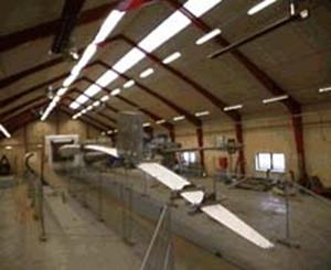
A 32 m rotor blade is fatigue tested by being bent cyclically in a flapwise direction for 5 million full cycles. A full flapwise test thus takes about three months.
The blades are bent using a cycle close to the natural frequency of the blade.
The natural frequency is the frequency with which the blade will oscillate back and forth, if you push it once in a certain direction and let go. The natural frequencies are different in the flapwise and edgewise direction: The blade tends to be much stiffer in the edgewise direction, thus it has a higher natural frequency for edgewise bending. Each blade is set in motion by an electric motor mounted on the blade which swings a weight up and down. The foundations which carry the blade socket have to be very solid: The foundation for the large blade socket consists of 2,000 tonnes of concrete.
10.2. Rotor Blade Materials
Rotor blades are usually made using a matrix of fibre glass mats which are impregnated with a material such as polyester (GRP = Glass fibre reinforced polyester). The polyester is hardened after it has impregnated the fibre glass. Epoxy may be used instead of polyester. Likewise the basic matrix may be made wholly or partially from carbon fibre, which is a lighter, but costlier material with high strength. Wood-epoxy laminates are also being used for large rotor blades.
10.3. The Purpose of Testing Rotor Blades
The purpose of rotor blade testing is to verify that laminations in the blade are, safe, i.e. that the layers of the rotor blade do not separate (delamination). Also, the test verifies that the fibres do not break under repeated stress.
10.4. Measuring Strains
Strain gauges, (i.e. flat electrical resistors which are glued on to the surface of the rotor blades being tested), are used to measure very accurately the bending and stretching of the rotor blades.
10.5. Monitoring Fatigue Testing
The measurement results from the strain gauges are continuously monitored on computers. Nonlinear variations in the pattern of bending may reveal a damage in the rotor blade structure.
10.6. Infrared Inspection (Thermography)
Infrared cameras are used to reveal local build-up of heat in the blade. This may either indicate an area with structural dampening, i.e. an area where the blade designer has deliberately laid out fibres which convert the bending energy into heat in order to stabilise the blade, or it may indicate an area of delamination or an area which is moving toward the breaking point for the fibres.
10.7. Modal Forms of Rotor Blade Vibrations
From the year 2000 blade testing (in Denmark) also includes a verification of the different modal forms of vibration of each blade. This is done using a special type of equipment which excites the blade vibrations at different frequencies and in different directions. Different modal forms of oscillation are also known when building musical instruments: A string on a violin may oscillate with is basic tone, i.e. the centre of the string moving up and down, but it will usually also oscillate with the first overtone or first harmonic, with two centres of oscillation located at a distance of 1/4 from each end of the string, moving at twice the frequency of the basic tone or natural frequency.
The reason why manufacturers of wind turbines are interested in studying and verifying the various forms of vibration frequencies in rotor blades, is that they have to make sure that the turbine on which the blade is to be mounted does not have some of the same natural frequencies as the rotor blade. Otherwise, a resonance may occur in the whole structure of the turbine, leading to undampened vibrations which may eventually wreck the whole wind turbine. We will return to this issue on the page on structural dynamics in the design section later in this guided tour.
10.8. Static Testing of Rotor Blades
Rotor blades are also tested for strength (and thus their ability to withstand extreme loads) by being bent once with a very large force. This test is made after the blades has been subject to fatigue testing, in order to verify the strength for a blade which has been in operation for a substantial amount of time.
11. Manufacturing Wind Turbine Towers
Rolling Conical Tower Sections
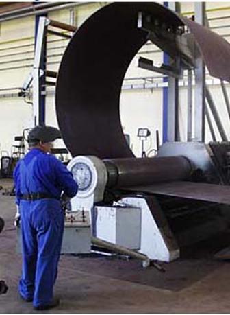
Most modern wind turbine towers are conical tubular steel towers, as we learned on the page about wind turbine towers.
This image from a tower manufacturer's workshop shows how a steel plate is rolled into a conical subsection for a wind turbine tower. It is a bit tricky to achieve the conical shape, since the tension (pressure) of the steel rollers has to be different at the two sides in order to make the plate bend properly.
Towers are assembled from these smaller, conical subsections which are cut and rolled into the right shape, and then welded together. Towers are usually manufactured in 20 to 30 m sections (65 to 100 ft.), the limiting factor being transportation on roads or rail.
Typical modern tower weights are 40 metric tonnes for a 50 m (165 ft.) tower for a turbine with a 44 m rotor diameter (600 kW), and 80 metric tonnes for a 60 metre tower for a 72 m rotor diameter (2000 kW).
Designed by the Turbine Manufacturer
Towers for wind turbines are generally designed by each turbine manufacturer, since the entire wind turbine has to be type approved as a unit. (The reasons are explained in the page about structural dynamics). So even if some towers are manufactured by independent producers, they are always specific for each manufacturer. Independent tower manufacturers are often also manufacturers of oil tanks or pressure vessels, since the machinery and safety inspection procedures are very similar.
Weight Matters
Tower weights (per installed power in kW) have declined by about 50% during the past five years due to more advanced design methods. Still, towers are a fairly heavy part of the wind turbine, so transportation costs are important. For larger markets it generally does not pay to transport towers more than 1000 km (600 miles) by road. In case the distance is larger (and the project is a large one), towers are usually manufactured locally.
Banana Peel Shaped Plates
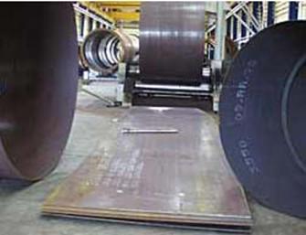
In order to end up with a cone-shaped section, the plate used for rolling has to be curved along the longest edges, and the short edges are not parallel. Most tower manufacturers use programmable laser cutting tools in order to obtain the appropriate shape for the steel plate.
Welding Wind Turbine Towers
Steel Sections are Powder Welded
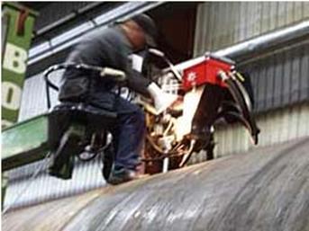
Each tower section is welded with a seam lengthwise, plus a circular welding seam to connect to the next section of the tower. This is done by placing the tower sections on a rolling bed which slowly rotates the tower, while an operator with a powder welding machine welds the sections from the outside... ...and another operator welds a corresponding set of seams on
the inside.
Checking Welding Seams for Safety
Welding seams in towers are checked using ultrasonic or x-ray devices. Important seams are checked 100%, while other seams are checked on a sample basis.
Installing and Assembling Wind
Turbine Towers
Attaching Towers to their Foundations
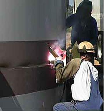
Towers are usually bolted onto the concrete foundations on which they are placed.
There are other methods, however, as in this case where part of the bottom section of the tower is cast into the concrete foundation, and where the lowest section of the tower is subsequently welded together directly on the site. This method requires that the tower be fitted with special guides and clamps to hold the two tower sections in place while the welding is being done. It also requires a small mobile tower factory including a generator, welding gear, and x-ray inspection equipment for checking the welding seams.
Flanges
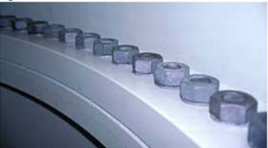
Wind turbine tower sections are bolted together using hot rolled steel flanges, which are welded to the end of each tower section. The flanges are made from killed steel. The image shows a pair of flanges.
Bolt Assembly
The next image shows how the tower sections are bolted together inside the tower. The quality of the flanges and the bolt tensions are important parameters for the safety of wind turbine towers.
Conclusions
Analysis
A. Drag or Lift device: Using drag it is possible to produce low voltage power at slower speed. Drag devices tend to work better for pumping water then producing electricity. Lift devices response to sudden change in wind conditions are less prevalent then drag devices. Lift devices tend to work better in higher speed winds then drag devices. Construction of a lift device could be more difficult to build or to purchase for a prototype.
B. Horizontal axis: Up wind or down wind rotor blade. Up wind a tail vane or other device is need to keep it positioned into the wind. This is not necessary for down wind systems, and also their blade can be semi-flexible because there is no chance that they can hit the tower.
C. Vertical axis: Giromill, Savonius, Darrieus. A vertical axis machine need not be oriented with respect to wind direction. Because the shaft is vertical the transmission and generator can be mounted at ground level. Although, vertical axis wind turbines have advantages, their designs are not yet as efficient at collecting energy form the wind as the horizontal machines. The Giromill has blades whose angle of attack is adjustable to optimize windmill performance under varying wind conditions. Savonius is self-starting and the simplest of the designs to construct, but is least efficient. Darrieus is not self-starting it requires a motor to position it blades into the wind before the wind can take over.
D. Furling or brake: Furling on blades, or nacelle. Brake on main shaft or high-speed shaft. Furling is very difficult to install on the blades but tend to work well. Furling on the nacelle tends to be easier by using spring load. Using brakes to reduce the rotor speed and protect the unit tend to be more expensive then furling and require more maintenance. Brakes are more commonly used on larger wind turbine devices. Brakes are more commonly placed on the high speed shaft, after the gear box transmission.
E. Positioning into wind: Vain or Motor: Using a vain to position into the wind is the cheaper solution to position the blades into the wind on up wind horizontal axis machines. Motor work well and can also be used to protect the machine in high wind speed, but add to the size of the wind turbines base and tower.
F. Power producing: Generator or Alternator. Generators produce DC power and are typically used on larger scale wind turbines, more so then alternators. Alternators produce AC power and are more commonly used on micro-turbines.
G. Tower: Welded steel frame or cylindrical pole. Guided or free standing. Welded steel frames are readily available on the market and are easy to erect. Cylindrical poles are easy to design and can also be found in standard sizes and lengths.
H. Sizing: Prototype tower height, rotor diameter, power. A smaller prototype will be less costly then a larger prototype. The tower will be no more then 6 ft tall. Rotor diameter will be no more then 3 ft, and is also limited by testing. A fan will be used to test the prototype, so the device should not be too large. Power produced will be limited by the sizing of the components and mainly determined by the wind speed and generating device's size.
7. Selection
A. A blades will be purchased to utilize drag and lift forces.
B. A three blades horizontal axis wind turbine will be designed for this project. Horizontal axis is the most common wind turbine design.
C. The turbine is pitch controlled.
D. Furling will be used to protect the machine against excessive wind speed. The furling device will be attached to the nacelle and support. Through the use of springs the wind turbine will reticulate or rotate back in excessive wind. A pin joint will create the rotation pivot, which will be mounted on the motor mount.
E. A remote control planes motor will be used in the reverse direction to generate power. The motors will be converted to a generation device by rotating the rotors in the opposite direction to motor propulsion. The motor will be fixed with a gear head assembly. The motors voltage range is 4.8v to 8.4v. The gear range is 64/12 providing a 5.33 gear ratio.
F. The tower will be made from a cylindrical tube.it-s height is 14m
G. The sizing of the prototype will be rotor diameter= 8m, hub= 1.4 m, tower= 14m, power of the turbine= 10 kW
A 10-kW wind turbine can generate about 16,000 kWh annually, more than enough to power a typical household
A 1.65-MW turbine can produce more than 4.7 million kWh in a year--enough to power more than 470 average households in the U.S.
t
RESULTS AND DISCUSSION
The Horizontal Wind Axis Wind Turbine (HWAT) was investigated theoretically and experimentally. The rotor has a radius of R = 4.376 m and was linearly twisted.
The airfoil MEL 002 type was used.
Blade Geometry: The result showed that the rotor have a maximum chord of 0.87 m at r/R of to 0.2 and minimum chord of 0.26 m at the tip with a maximum twist of 19.3
Torque Coefficient (C Q ): maximum CQ of 0.09 was obtained at l of 4.8. The experimental data showed that the torque coefficient of 0.0484 at l of 2.3142 for the rotor.
Power Coefficient (C P ): maximum C P of 0.46 was obtained at l of 5.5. The experimental data showed that the power coefficient of
0.1121 at l of 2.3142 for the rotor.
Efficiency: theoretical efficiency for the rotor was 0.84 at l of 1. It is clear from this result, as the wind speed increases the efficiency decreases, because the energy from wind is proportional with the wind speed. Therefore the ratio of energy extract from the wind to the available energy will decrease, which leads to decreasing of the efficiency.
Effect of Yawing Angle ( d ): The theory and experimental results showed the power and torque coefficients are affected by yawing the rotor The theory showed Cp drop from 0.46 to 0.41 at yaw angle of 15.0 degree and to 0.295 at yaw angle of 30 degree. The maximum C Q , also dropped from 0.09 to 0.084 at yaw angle of 15 degree and to 0.068 at yaw angle of 30 degree. A good agreement was achieved between the theory and experiment at yaw angle of 0,15 and 30 for single low tip speed ratio (l ) value.
The modeling of wind turbine blades presents a difficult challenge. Their complicated geometry and material composition as presented for example by a change of the cross sections shape along the length and the use of .ber materials -causes an elastic coupling of the blades .exure, torsion, extension and shear. For aeroelastic computations of wind loads and dynamic stability analysis of a wind turbines motion, this coupling mechanism is of vital interest.
Finite Element (FE) methods give a detailed description of deformations of a loaded blade, but their large number of degrees of freedom and the high eigen frequencies of such a model associated with a required .ne spatial discretization cause extremely long computation times when simulating in the time domain.
One alternative to FE models is the development of a blade model relying on the theory of rods. The basic idea is to characterize the blade motion by few (say10)partial differential equations in which there is but one independent spatial variable. These partial differential equations can easily be further discretized to ordinary differential equations as desired when simulating in the time domain.
Research and Development in Wind
Energy
For wind turbine manufacturers, the basic aim of research and development of wind turbines is to be able to manufacture ever more cost effective machines.
Photograph
Basic Aerodynamics Research
Wind turbines engineers use techniques such as stall, which aircraft designers try to avoid at all costs. Stall is a very complex phenomenon, because it involves airflows in three dimensions on wind turbine rotor blades. (e.g. the centrifugal force will induce an airflow which makes the air molecules move radially along the rotor blade from its root towards the tip of the blade).
3D computer simulations of airflows are rarely used in the aircraft industry, so wind turbine researchers have to develop new methods and computer simulation models to deal with these issues.
Computational Fluid Dynamics, or CFD, is a group of methods that deal with simulating air flows around e.g. rotor blades for wind turbines. The picture shows a computer simulation of the air flows and pressure distributions around a wind turbine rotor blade moving towards the left.
Aerodynamic Improvement Devices
A number of technologies known from the aircraft industry are increasingly being applied to improve the performance of wind turbine rotors. One example is vortex generators, which are small fins, often only about 0.01 metre (0.4 inch) tall, which are fitted to the surface of aircraft wings. The fins are alternately slightly skewed a few degrees to the right and the left. The fins create a thin current of turbulent air on the surface of the wings. The spacing of the fins is very accurate to ensure that the turbulent layer automatically dissolves at the back edge of the wing. Curiously, this creation of minute turbulence prevents the aircraft wing from stalling at low wind speeds. Wind turbine blades are prone to stalling even at low wind speeds close to the root of the blade where the profiles are thick. Consequently, on some of the newest rotor blades you may find a stretch of one metre or so along the back side of the blade (near the root) equipped with a number of vortex generators.
WIND ENERGY SYSTEM COMPONENTS
Wind turbines are typically listed by size according to the potential to generate electricity in ideal wind conditions. This is known as the "rated capacity." The ability to generate electricity is measured in watts. Watts are very small units, so the terms kilowatt (kW, 1,000 watts) and megawatt (MW, 1 million watts) are most commonly used to describe the capacity of wind turbines or other power plants. Wind turbines being manufactured now have capacity ratings ranging from 250 watts to 1.65 MW.
Towers
To access the best wind resource, windmills and wind turbines are usually placed on high towers. Because of their lighter weight, wind turbines can use lighter-weight towers than can conventional mechanical windmills. Towers come in two main types: guyed (lattice or pole) towersand free-standing self-supporting towers. If the topography of the site will allow the space for a guyed tower, this will be the lower-cost approach.
Towers range from 12-37 meters for small wind applications and 30-75 meters or higher for utility-scale turbines. In general, the height of the tower should be 10 meters above any obstacles within 100 meters.
Hybrid System Combinations
Many electricity generation systems use more than one kind of genera-tor, to provide a smoother supply of power. Many systems pair one or more wind turbines with a photovoltaic (solar) array, elements of passive solar heating &/or lighting, and a back-up diesel generator. Depending on the local re-sources, a power system can include biomass, hydro, or other generating sources in the hybrid system.
Pump/Motor
If the wind power is to be used for pumping water, the system designer must select the pump based on the pumping head and flow requirement, wind turbine electrical output, and site conditions. Submersible pumps are most commonly used for drilled wells. At low heads and for surface water sources, hori-zontal-axis centrifugal pumps can be used with good results. One of the appealing factors of wind electric water pumping is that off-the-shelf submersible pumps can be used. While these units are designed to run at the normal electrical line frequency of 50 or 60 Hz, if certain precautions are taken they can be run efficiently at a broad range of frequencies.
Storage
In addition to the electricity generators most hybrid systems have com-ponents for storing power so that usage need not be determined by the time of electricity production. The most common storage device is the lead-acid bat-tery. If the wind energy conversion system is to pump water, the designer will need to arrange for storage of the pumped water.
Energy Converters
An electronic component to convert direct current (DC) electricity to alternating current (AC) and vice versa is necessary to shape the power from the turbine into energy that is useful for industrial &/or household appliances
Balance of System
The rest of the system components include monitoring equipment, a de-vice to shed excess energy produced by the system, and the wiring and the hardware needed to complete the system.
APPLICATIONS
Water Pumping
The livelihood and well-being of people, animals, and crops depends on a reliable, cost-effective supply of clean water. Mechanical wind water pumping machines have been used to pump water from wells for centuries. The technology of modern mechanical water pumpers is relatively simple, the maintenance requirements are modest, and the replacement parts are not difficult to obtain. The mechanical water pumper is the best option in some circumstances. However, because it must be placed close to the water source, it is often unable to capture the best wind resources.
A wind electric pumping system overcomes some of the problems with the simple wind water pumper. This system generates electricity, which, in turn, runs an electric pump. Wind electric pumping systems allow greater siting flexibility, higher efficiency of wind energy conversion, increased water out-put, increased versatility in use of output power, and decreased maintenance and life-cycle costs.
Industrial Applications
The number of dedicated industrial applications for wind power continues to grow. Small wind power systems are ideal for applications where storing and shipping fuel is uneconomical or impossible.
Wind power is currently being used for the following applications:
telecommunications
radar
pipeline control
navigational aids
cathodic protection
weather stations/seismic monitoring
air-traffic control
Wind machines in industrial applications typically encounter more ex-treme weather than home power systems and must be designed to be robust with very minimal maintenance.
There are many situations where you might need a small amount of electricity, for instance running gate openers, safety lights, water level indicators and other low-power devices. Or even water pumping. A horizontal axis eind turbine might not always be the answer becouse it requires complicated calculations and sometimes a to big cost taking in consideration the need.
a small horizontal axis turbine, can be dangerous when close to the ground and in touching distance, so a a Savonius rotor can be the answer.
This type of vertical axis rotor is very robust and durable if built correctly, is relatively slow turning and can be easily built at home, without the hassles of aerofoil blade design and other problems associated with horizontal axis 'propeller' type turbines.
What's more, unlike a horizontal axis turbine, a Savonius is always facing the wind, and more importantly for this site, is not badly affected by turbulence.
REFERENCES
Johnson G. L, "Wind Energy System", Prentice-Hall, INC., New Jersey 1985.
2. "Wind Energy in Europe Time for Action ", EWA Strategy Document, Third Draft, Aug. 31, 1990.
3. Brand. A. J, Dekker. J. W. M, Groot C. M. and Spath M., "Field Rotor-Aerodynamic: TheRotating Case", 16 th ASME Wind Energy Symp., Jan. 1997.
4.Huyer S. A., Simms D., and Robinson M. C., " Unsteady Aerodynamics Associated with a Horizontal-Axis Wind Turbine", AIAA Journal, Vol. 34, No. 7, July 1996.
5. Hickok F., "Hand book of Solar and Wind Energy", Chaners books International, INC., Boston.
6. Eldridge F. R., "Wind Machines", Van Nostrand ReinHold Company, NewYork, 1980.
7. Daniel V. H., "Wind Power", Van Nostrand ReinHold Company, New York ,1981.
8. Matsumiya H., "Performance of New MEL-Wing Sections for Wind Turbines", EuropeanCommunity Wind Energy Conference, Spain, 1990, pp 258-263.
9. Kragten A., "Rotor Design", Wind Energy Group, University Eindhoven, Netherland, 1989.
11. Liu H., " Wind Engineering, A Handbook for Structural Engineers ", Prentice-Hall INC, New Jersey 1991.
Omar A. A., "Performance Analysis of HAWT Rotor Blades", Master Thesis, Seoul National University, 1994.
13. Somers, D.M., "Effect of Airfoil Thickness and Maximum Lift Coefficient on Roughness Sensitivity," Airfoils Inc., State College, PA, October 1998.
Gans, Paul J. 2000, Windmills [On-line]
https://scholar.chem.nyu.edu/~tekpages/windmills.html
17 Sept. 2002.
Krohn, Soren 2001, A Wind Energy Pioneer: Charles F. Brush [On-line]
https://www.windpower.dk/pictures/brush.htm
Oct. 2002
American Wind Energy Association. 2001, New York State Wind Energy [On-Line]
https://www.awea.org/projects/newyork.html
ept. 2002
National Renewable Energy Laboratories. 2002
15 Nov. 2002
18. Gipe, Paul, Wind Power for Home & Business: Renewable Energy for the 1990s and Beyond, Chelsea Green Publishing Co., Post Mills, VT (1993)
|
Powered by https://www.preferatele.com/ cel mai complet site cu referate |
|