NURBS Tutorials for 3DS MAX R2 Beta
Preliminary Draft
Ian Buono & Randy Clark
Kinetix
May 20 July 11, 1997
These tutorials introduce you to NURBS for 3D Studio MAX. NURBS are a powerful way to model surfaces. When you model with NURBS, you can choose from a variety of approaches. These tutorials present some of the most common techniques, to help you choose the approach to making a model of your own.
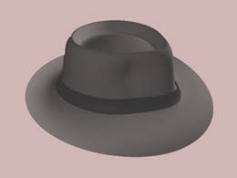
In this first tutorial, you begin to create a fedora hat. You finish the hat in the second tutorial.
[SUGGESTION: Read this document in Word to see the illustrations in color.]
In 3DS MAX R2 you can create curves and surfaces using NURBS (Non-Uniform Rational B-Splines). The advantage of NURBS technology is the ease with which you can create complicated surfaces. NURBS curves are one way to build surfaces. If you know what the outline or the edge of a surface ought to look like, NURBS curves are a convenient way to begin.
To create the hat, you begin with a NURBS curve, and then lathe it. Lathing a NURBS curve is similar to lathing a spline. However, you create the initial curve in a different way, and once you have lathed the curve to create the NURBS surface, you use NURBS facilities to add detail to the model. The overall steps are as follows:
· & 18318b116s nbsp; Create the curve.
· & 18318b116s nbsp; Apply a Lathe modifier, and set the lathed output to be a NURBS surface.
· & 18318b116s nbsp; (Tutorial 2) Convert the hat to a NURBS surface and edit the surface by transforming some of its control vertices.
In the first step, you create the curve to be lathed. There are two different kinds of NURBS curves in 3DS MAX R2:
· & 18318b116s nbsp; Point Curves are controlled by points. The points always lie on the curve, which passes through them.
· & 18318b116s nbsp; CV Curves are controlled by control vertices (CVs). The CVs don't necessarily lie on the curve. Instead, they form a control lattice that surrounds the curve.
· & 18318b116s nbsp;
control vertex (CV)
control lattice point
Point curve CV curve
A point curve and a CV curve
In general, it is easier to visualize a point curve, because the curve passes through the points. On the other hand, CVs are weighted, while points are not. Increasing the weight of a CV pulls the curve toward the CV; decreasing the weight relaxes the curve away from the CV. This can be a useful way to tune how a CV curve looks.
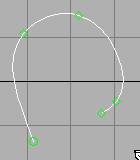
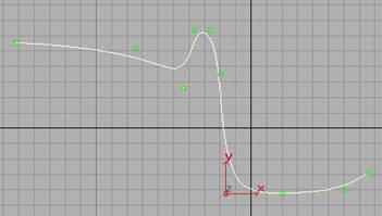
In this example, you use a CV Curve. When you create a curve you plan to lathe, the idea is to create a half-outline of the lathed surface. For the fedora, the curve should look like this:
CV curve to describe the half-outline of a hat
Create the CV curve:
1. & 18318b116s nbsp;
![]() Go to the Create command panel
Go to the Create command panel
2. & 18318b116s nbsp;
![]() Click to turn on Shapes.
Click to turn on Shapes.
3. & 18318b116s nbsp; Choose NURBS Curves from the dropdown list.
4. & 18318b116s nbsp; Click to turn on CV Curve.
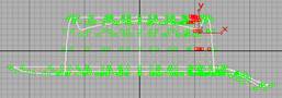
5. & 18318b116s nbsp; In the Front viewport, click and drag to create the first CV, as well as the first curve segment. Release the mouse to add the second CV. Continue clicking to add CVs, creating an outline similar to the one shown in the illustration. Right-click to finish creating the curve.
You probably need from 10 to 15 CVs to create the curve. Don't worry if the initial curve doesn't look quite right. NURBS curves are easy to edit, as explained in the next set of steps.
Tip: As in spline creation, you can use BACKSPACE to undo the creation of previous CVs.
In the next group of steps, you adjust the curve to correct mistakes and improve its appearance.
1. & 18318b116s nbsp;
![]() With the CV Curve selected, go to the Modify
panel.
With the CV Curve selected, go to the Modify
panel.
2. & 18318b116s nbsp; In the Modifier Stack rollout, click to turn on Sub-Object. If Curve CV is not already chosen as the sub-object level, choose it from the drop-down list.
3. & 18318b116s nbsp;
![]() Click to turn on Select and Move in the
toolbar.
Click to turn on Select and Move in the
toolbar.
4. & 18318b116s nbsp; Select CVs and move them until the curve appears the way you want it. Notice how moving a CV changes the shape of the curve as well.
Select one CV by clicking, or multiple CVs by dragging a region. The other sub-object selection modes work for CV sub-objects: CTRL to add to a selection, ALT to remove from a selection.
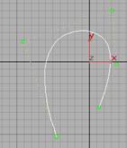
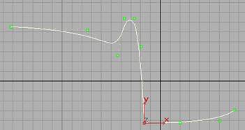
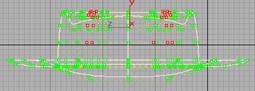
Once the curve appears as it does in the previous image, or in a variation you are satisfied with, you are ready to turn it into a hat-shaped surface.
The CV curve after lathing it
Use Lathe to create the surface:
1. & 18318b116s nbsp; In the Modify panel, apply a Lathe modifier to the curve.
2. & 18318b116s nbsp; In the Lathe modifier's Parameters rollout, set the axis to Y, then set the alignment to Min.
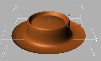
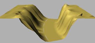
Lathe creates the hat-shaped surface.
You might need to turn on Flip Normals to see the hat correctly in shaded viewports.
3. Increase the number of segments to 30 to make the hat smoother.
Use a perspective viewport to look at what you've created:
1. & 18318b116s nbsp; Make the perspective viewport active.
2. & 18318b116s nbsp; Click Zoom Extents.
3. & 18318b116s nbsp; If the viewport isn't already shaded, right-click its label and choose Smooth + Highlights.
4. & 18318b116s nbsp; Choose Views/Viewport Configuration (or right-click any viewport navigation button).
5. & 18318b116s nbsp; In the Viewport Configuration dialog's Rendering Methods panel, turn on Force 2-Sided, and then click OK.
The hat should appear much as it does in the previous illustration.
Suggestion: You can change the curve object's color to change the color of the hat surface as well.
Save your work. In the next tutorial, you edit the hat to make it look more realistic.
The hat you created in the previous tutorial is unrealistically symmetrical. Also, the crease between the crown and the brim isn't sharp enough. In this tutorial, you edit the hat model using two different NURBS facilities:
· & 18318b116s nbsp; You sharpen the brim by adjusting the original curve.
· & 18318b116s nbsp; You change the form of the hat by transforming some of its CVs.
To do this, you have to first turn the hat into a NURBS surface (a CV Surface). Lathing a NURBS curve doesn't automatically create a NURBS surface it simply creates a curve with a Lathe modifier on it. To make the lathed curve into a NURBS surface, you have to collapse its stack. Collapsing to a NURBS surface is similar to collapsing a modified object into an editable mesh.
To sharpen the crease between the crown of the hat, you adjust the original curve, using the property of a CV's weight. All the CVs in a curve or surface have a weight value that is relative to the other CVs. If you leave weight unchanged, the curve or surface appears as you originally drew it. Increasing the weight of a CV draws the curve or surface closer to that CV. Decreasing the weight relaxes the surface away from the CV.
Increase the weight at the crown/brim seam:
1. & 18318b116s nbsp; Load the model if you saved it before, and select the hat.
2. & 18318b116s nbsp; Choose NURBS Curve in the modifier stack.
The lathed hat disappears and the curve reappears. You might want to choose Zoom Extents All to get a better view.
3. & 18318b116s nbsp; Make the Front viewport active, then click to turn on Sub-Object. If Curve CV doesn't appear as the sub-object level, choose Curve CV from the drop-down list.
The curve's CVs and CV lattice appear.
4. & 18318b116s nbsp;
![]() Click to select the CV at the seam between
the crown and the brim.
Click to select the CV at the seam between
the crown and the brim.
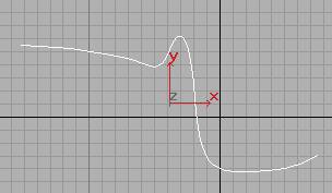
5. & 18318b116s nbsp; In the CV rollout, increase the weight of the CV until the crease appears sharper.
 Weight = 1.0
 Weight = 9.0
Increasing weight increases sharpness of the curve
Tip: If your curve doesn't have a CV right at the crease, click Refine in the CV rollout and then click the curve at the crease. Then turn Select on again, select the new CV, and increase its weight.
Return to the lathe level:
1. & 18318b116s nbsp; Click to turn off Sub-Object.
2. & 18318b116s nbsp; Choose Lathe from the modifier stack.
3. & 18318b116s nbsp; Click Zoom Extents All.
Now the crease between crown and brim is more distinct.
4. & 18318b116s nbsp; Save your work.
Make sure the model is as you want it before you proceed to the next group of steps. When you turn the hat into a NURBS surface to edit it, you lose the ability to adjust the curve as you just did.
You now have the basic shape of the hat, but you still need to pull down the front of the brim and pinch the top of the crown. The easiest way to do this is to turn the hat into a CV Surface and then transform some of its CVs.
Turn the hat into a NURBS surface:
1. & 18318b116s nbsp; Make sure the hat is selected.
2. & 18318b116s nbsp; Choose NURBS as the output of the Lathe modifier.
Choosing NURBS as the output means that when you collapse the stack, the resulting surface will be a NURBS surface.
3. & 18318b116s nbsp;
![]() Click Edit Stack.
Click Edit Stack.
4. & 18318b116s nbsp; In the Edit Modifier Stack dialog, click Collapse All. Answer Yes to the warning and then click OK to leave the dialog.
Now you're ready to edit the hat as a surface.
Select the brim and move it downwards:
1. & 18318b116s nbsp; Click to turn on Sub-Object and choose Surface CV as the sub-object level.
The CVs and control lattice appear.
(If you can't see the control lattice, turn on the Display Lattice toggle at the bottom of the CV rollout.)
2. & 18318b116s nbsp;
![]() Click to turn on Move.
Click to turn on Move.
3. & 18318b116s nbsp; In the Top viewport, drag to select the CVs at the bottom of the surface (see the illustration below).
4. & 18318b116s nbsp; In the Left viewport, move the CVs downwards to give the brim a downward flip.
Tip: ![]() Lock Selection is useful for selecting in
one viewport and then transforming in another.
Lock Selection is useful for selecting in
one viewport and then transforming in another.
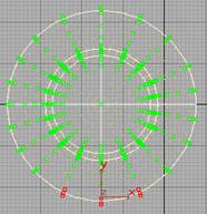
Select the front rows in the Top viewport, move them down in the Left viewport
Save your work again. The last refinement to the hat model is to give the top of the crown a pinch.
To get an effective-looking pinch, the front part of the crown should have more CVs. So the first thing to do is use the refine tool to add CVs.
Add CVs to the hat:
1. & 18318b116s nbsp; While you're at the Surface CV sub-object level, click to turn on Refine Row in the CV rollout.
For a lathed surface, rows radiate out from the center of the lathe, which is what we want in this case.
2. & 18318b116s nbsp; In the Top viewport, click the surface at approximately the locations shown in the illustration. Click each location twice. You might have to move the mouse a bit before the second click, to get the second new row to appear.
Refining adds rows of CVs to the surface. When you use Refine, other rows move. This is because when you refine a curve surface, 3DS MAX adjusts the CVs to maintain the object's curvature. Otherwise the surface itself would have to change, which would defeat your purpose.
![]()

Click twice to refine After refining
Locations to click to refine the hat surface
Now you can add the pinch by scaling.
CV selection for pinching the crown of the hat
1. & 18318b116s nbsp; In the Top viewport, select the CVs shown in the illustration. (Don't worry if the rows you added aren't precisely in the location of the rows shown here.)
Use CTRL to add CVs and ALT to remove CVs from the selection set, as you do with other 3DS MAX sub-objects.
2. & 18318b116s nbsp; In the Front and Left viewports, deselect the CVs that lie on or near the crease between the crown and the brim. (See the following illustration.)
Select only CVs that lie on the crown
3. ![]() Turn on Non-Uniform Scale.
Turn on Non-Uniform Scale.
4. Set the reference coordinate system to View.
5. ![]() Set the coordinate system to Transform
Coordinate Center.
Set the coordinate system to Transform
Coordinate Center.
6. Set the XYZ constraints to XY.
7. Scale the selected CVs down to about 85%.
Now you have the basic shape of a Fedora hat. If you want to, you can try more CV transformations to improve the appearance of the pinch.
Creating a hatband isn't part of this exercise at this time. Here is one way you might create it:
· & 18318b116s nbsp; Create a V Iso curve where the brim of the hat meets the crown.
· & 18318b116s nbsp; Create another V Iso curve higher up on the crown.
· & 18318b116s nbsp; Create a Ruled surface between the two V Iso curves.
Now you have surface that models a hatband. However, it is the same color as the hat itself unless you use a Multi/Sub-Object material to assign the hat and the hatband two submaterials of different colors.
In the next exercise, you create a canyon.
Modeling terrain is a common use of surfaces. In this tutorial, you create a canyon whose walls are modeled by dependent Blend surfaces. As you update the parent surfaces the canyon rims the dependent surfaces change to match the updates. This relational property of dependent surfaces is one of the reasons NURBS modeling is so powerful.
The first step is to create a NURBS Point Surface that will be the left rim of the canyon.
Create the left rim:
1. & 18318b116s nbsp;
![]()
![]() In the Create Panel, choose Geometry and
NURBS Surfaces, then click to turn on Point Surf.
In the Create Panel, choose Geometry and
NURBS Surfaces, then click to turn on Point Surf.
2. & 18318b116s nbsp; In the Top viewport, drag to create the initial point surface. Start at about -100, 100 and drag to about to -75, 100.
3. & 18318b116s nbsp; In the creation parameters set Width Points to 20. This adds more rows of points to the surface.
Next you create a CV Surface to become the canyon's floor. You use the Modify command panel to ensure that the canyon floor is a sub-object of the canyon model. Two surfaces must be sub-objects of the same NURBS model before you can create a Blend surface between them.
Create the canyon floor:
1. & 18318b116s nbsp;
![]() Go to the Modify Panel.
Go to the Modify Panel.
2. & 18318b116s nbsp; Open the Create Surfaces rollout.
3. & 18318b116s nbsp; Click to turn on CV Surf.
4. & 18318b116s nbsp; In the Top viewport, drag out the CV Surface. Start at about -30, 100 and drag to about 0, 100.
Initially the floor is at the same level as the rim. It should be below the rim.
Place the floor beneath the rim:
1. & 18318b116s nbsp; Click to turn on Sub-Object and choose Surface as the sub-object level.
2. & 18318b116s nbsp; Make sure the transform coordinate system is View.
3. & 18318b116s nbsp;
![]() In the Front viewport, select the canyon
floor CV Surface and move it down in the Y-direction
about 50 units.
In the Front viewport, select the canyon
floor CV Surface and move it down in the Y-direction
about 50 units.
The final independent component to create is the canyon's right rim. To do this you use another method for creating surface sub-objects: SHIFT+cloning the original rim.
Create the right rim:
· & 18318b116s nbsp;
![]() With Surface still the sub-object level and
Move still the active transform, hold down the SHIFT key and drag from the left
rim surface to the right approximately 200 units.
With Surface still the sub-object level and
Move still the active transform, hold down the SHIFT key and drag from the left
rim surface to the right approximately 200 units.
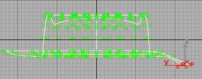
At this point, the rims and the floor of the canyon should appear something like the illustration, which shows a rotated perspective view.
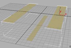
Canyon rim and floor surfaces
Now you're ready to create the canyon walls by blending between the rims and the canyon floor.
Create the canyon walls:
1. & 18318b116s nbsp; Click to turn off Sub-Object mode.
2. & 18318b116s nbsp; Open the Create Surfaces rollout, and then click to turn on the Blend button.
Blend surfaces connect the edge of one surface to another. When you create them, you hold down the mouse near an edge you want to connect, drag to the edge of the other surface, and then release the mouse.
3. & 18318b116s nbsp; Drag from the left edge of the right rim surface to the nearest edge of the floor surface.
3DS MAX creates a surface that smoothly blends between the right rim and the canyon floor.
4. & 18318b116s nbsp; In the same way, drag from the left edge of the floor surface to the right edge of the left ridge surface.
Tip: If either new blend surface doesn't appear in shaded viewports, turn on Force 2-Sided in the Viewport Configuration dialog.
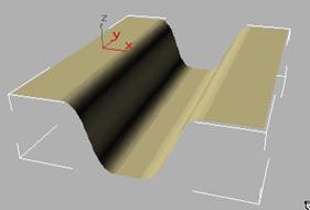
Blend surfaces forming the canyon walls
Now you have a set of surfaces that in the shape of an extremely regular canyon or a trough. To make the canyon more realistic, you will add peaks and valleys to the canyon rims. Because the blends are dependent surfaces, their shape will change to follow the adjustments you make to their parent surfaces.
The Noise modifier is ideal for giving a realistic look to the canyon rim, because it generates a fractal noise pattern. In addition, you will bend the floor of the canyon. To use these modifiers, you also use the NSurf Sel modifier. This is a selection modifier for NURBS surface objects. You can also apply a modifier to a NURBS sub-object selection without using NSurf Sel, but then you lose the ability to go back into the modifier stack and change settings later.
[NOTE: In the beta build, sometimes the sub-objects selected by NSurf Sel become deselected. If you lose the effect of the Noise or Bend modifiers, go into the associated NSurf Sel modifier and select the points or CVs again. This problem appears to be intermittent.]
Add noise to the canyon rims:
1. & 18318b116s nbsp; Turn off Sub-Object.
2. & 18318b116s nbsp; Apply an NSurf Sel modifier (in the Modifiers rollout, click More and choose from the list).
3. & 18318b116s nbsp; In the NSurf Sel modifier, choose Point as the sub-object level.
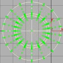
4. & 18318b116s nbsp; Select the right row of the left rim surface and the left row of the right rim surface.
Selection of points at the edges of the rims
3. Apply a Noise modifier. This will affect the sub-object selection of points passed up the stack by NSurf Sel.
4. In the Noise modifier's parameters, set the Scale = 30, X Strength = 25, and Z Strength = 15. Set the Fractal toggle.
Now the canyon's rims and walls have a realistically fractal appearance.
Add a curve to the canyon floor:
1. & 18318b116s nbsp; While the Noise modifier is chosen in the modifier stack, apply another NSurf Sel modifier.
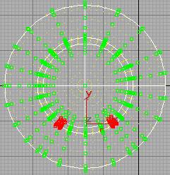
2. & 18318b116s nbsp; In the NSurf Sel modifier, choose Surf CV as the sub-object level.
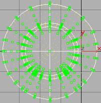
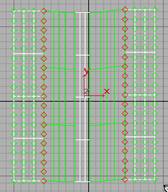
3. & 18318b116s nbsp; Drag to select all the CVs on the canyon floor.

Selection of the canyon floor
4. & 18318b116s nbsp; Apply a Bend modifier.
5. & 18318b116s nbsp; Set the Angle to 50 and the Bend Axis to Y.
Now the canyon bends as well.
The canyon is now complete. We encourage you to experiment with other options in the NURBS feature set. More tutorials will be added in the future.
|
