Preliminary Document
Randy Clark
Kinetix Tech Pubs
July 10, 1997
[NOTE: This draft describes 3DS MAX R2 Beta build 0.2.15. If you are still using an earlier build, some features that the document assumes are available won't be functioning yet. RC]
3D Studio MAX R2 Beta provides NURBS surfaces and curves. NURBS have become an industry standard for designing and modeling surfaces. They are especially suited for modeling surfaces with complicated curves. NURBS stands for Non-Uniform Rational B-Splines. The tools for modeling with NURBS do not require an understanding of the mathematics that produces these objects. NURBS are popular precisely because they are easy to manipulate interactively, and because the algorithms that create them are both efficient and numerically stable.
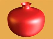

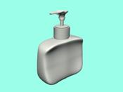
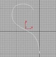
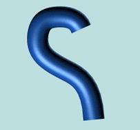
Vase from lathed NURBS curve Spaceship from cylindrical NURBS
surface Lotion bottle's spout and
body
with fused and scaled control vertices modeled with NURBS surfaces
(the tubes are rendered NURBS curves)
Models created using NURBS
[SUGGESTION: Read this document in Word to see the illustrations in color.]
In 3DS MAX, you can also model surfaces using polygonal meshes or patches. Compared to NURBS surfaces, meshes and patches have these shortcomings:
It is more difficult to create complicated curved surfaces using polygons.
Because meshes are faceted, facets appear at the edge of rendered objects. You must have a large number of small faces to render a smoothly curved edge.
NURBS surfaces, on the other hand, are analytically generated. They are more efficient to calculate, and you can render a NURBS surface that appears to be seamless. (A rendered NURBS surface is actually approximated by polygons, but the NURBS approximation can be very fine grained.)
[NOTE: Some advanced features for NURBS modeling, such as trimming, are under development at present and will become available as a separate feature set after the shipment of 3DS MAX R2.0.]
NURBS for 3DS MAX R2 Beta
NURBS Models: Objects and Sub-Objects
Creating NURBS Models
Working with NURBS Models
Modifying NURBS Models and Creating Sub-Objects
Using the NURBS Toolbox to Create Sub-Objects
NURBS Curves
CV Curves and CV Surfaces
Points, Point Curves, and Point Surfaces
Sub-Object Selection
Dependent Sub-Objects
NURBS and Modifiers
Deforming NURBS Objects
NURBS Objects and the UVW Map Modifier
NURBS and Animation
Operations that Remove Animation
NURBS Concepts
Creating NURBS Curves
NURBS Curve Creation Parameters
Keyboard Entry for Curves
Creating NURBS Surfaces
NURBS Surface Creation Parameters
Keyboard Entry for Basic Surfaces
Creating NURBS Surfaces from Geometric Primitives
Attaching and Importing 3D Studio MAX Objects
Using Imports
Creating Dependent Curves
Toolbox Buttons for Creating Curves
Curve Fit
Transform
Blend
Offset
Mirror
Fillet
Chamfer
U and V Iso
Creating Dependent Surfaces
Toolbox Buttons for Creating Surfaces
Transform
Blend
Offset
Mirror
Extrude
Lathe
Ruled
U Loft
Cap
Creating Independent Surfaces from Curve Objects
Using Points
Toolbox Buttons for Creating Points
Point
Point Point
Curve Point
Surf Point
Curve-Curve
Display Controls for NURBS Models and Surfaces
Curve and Surface Approximation
Curve Approximation
Surface Approximation
Common Sub-Object Controls
Transforming Sub-Objects
Selection Controls
Visibility
Make Independent
Detach and Copy
Point and CV Sub-Object Controls
CV Weights
Adding and Deleting Points or CVs
Fusing Points or CVs
Affect Region
Curve Controls
Delete
Make First
Reverse
Join
Break
CV Curve Degrees
Closing Curves
Surface Controls
Delete
Make Loft
Rendering
Breaking a Surface
Extend
Join
Close
The NURBS Select Modifiers
Glossary
Like 3DS MAX Shape objects, a NURBS model can be an assemblage of multiple NURBS sub-objects. For example, a NURBS object might contain two surfaces that are separate in space. Both NURBS curves and NURBS surfaces are controlled by either point or control vertex (CV) sub-objects. Points and CVs behave somewhat like the vertices of spline objects in 3DS MAX, but there are differences.
The parent object in a NURBS model is a NURBS surface. Sub-objects can be any of the objects listed here:
Surfaces. There are two kinds of NURBS surfaces in 3DS MAX. A Point Surface is controlled by points, which always lie on the surface. A CV Surface is controlled by control vertices (CVs). Instead of lying on the surface, CVs form a control lattice that surrounds the surface.
Curves. There are also two kinds of NURBS curves in 3DS MAX. These correspond exactly to the two kinds of surfaces. A Point Curve is controlled by points, which always lie on the curve. A CV Curve is controlled by control vertices (CVs), which don't necessarily lie on the curve.
Points. Point Surfaces and Point Curves have point sub-objects. You can also create separate point sub-objects that are not part of a surface or a curve.
CVs. CV Surfaces and CV Curves have CV sub-objects. Unlike points, CVs are always part of a surface or a curve.
Imports. Imports are 3DS MAX objects including other NURBS objects. Within the NURBS model, they render as NURBS; but they retain their original parameters and modifiers.
3DS MAX R2 Beta provides a variety of ways to create NURBS surfaces. This is a summary of how you create top-level, parent NURBS objects:
You can create NURBS curves in the Shape panel of the Create command panel.
Note: NURBS curves can have curve and point sub-objects, but they can't have surface sub-objects.
You can create NURBS surfaces in the Geometry panel of the Create command panel. When you use this technique, the NURBS surface is initially a flat rectangle. You can alter it using the Modify command panel.
You can turn a 3DS MAX geometry primitive into a NURBS object by using the Edit Stack button in the Modify command panel.
The primitive objects you can convert to NURBS objects are the Standard Primitives, not the Extended Primitives.
When you work with NURBS models, usually you follow these overall steps:
Create one NURBS object as the "starter" object. This can be either a surface object, or a converted geometry primitive.
Often modelers like to identify a single, master surface as the main component of the model. Converted geometry primitives are good if you want the starter surface to become the master surface. See "Creating NURBS Surfaces from Geometric Primitives," below. Point and CV surfaces are good as starters for rectangular surfaces.
Go to the Modify panel. In the modify panel, you can edit the original object, or you can create additional sub-objects as described in the following section.
You might even choose to delete the original, starter object once you have built a model from newer sub-objects.
Going immediately into the Modify panel avoids the problem of creating additional top-level NURBS objects, which you can't use to build relational, dependent sub-objects as described in the sections that follow.
There are some general references for modeling with NURBS, including Curves and Surfaces for Computer-Aided Geometric Design: A Practical Guide by Gerald Farin (Academic Press, fourth edition 1996) and Interactive Curves and Surfaces: A Multimedia Tutorial on Computer Aided Graphic Design by Alyn Rockwood and Peter Chambers (Morgan Kaufman Publishers 1996).
NURBS are immediately editable when you enter the Modify command panel. You don't have to apply a modifier, as you do for most kinds of 3DS MAX objects.
While you are editing a NURBS object in the Modify command panel, you can create sub-objects "on the fly," without having to go back to the Create panel. This is an exception to the way you usually use 3DS MAX creating objects only in the Create command panel. The Modify command panel for NURBS curve and NURBS surface objects includes rollouts that let you create new NURBS sub-objects.

Rollouts for NURBS sub-object creation
This is a summary of how to create sub-objects:
Both curves and surfaces have a rollout for creating points. A point you create individually is either an independent point or a dependent point tied to other NURBS geometry.
Both curves and surfaces have a rollout for creating curves. Curve sub-objects are either independent Point Curves or CV Curves, or they are dependent curves whose geometry is based on other curves already present in the model. For example, a Blend curve is a dependent curve sub-object that connects the endpoints of two other curves (the parent curves must both be of the same type either Point or CV).
Surfaces have a rollout for creating surfaces. Surface sub-objects are either independent Point Surfaces or CV Surfaces, or they are dependent surfaces whose geometry is based on other surfaces already present in the model. For example, a Blend surface is a dependent surface sub-object that connects the edges of two other surfaces.
You can attach 3DS MAX objects. If the attached object is not already a NURBS object, it is converted to NURBS geometry. A NURBS curve can attach another NURBS curve or a spline curve. A NURBS surface can attach a curve, another NURBS surface, or a convertible 3DS MAX object. The attached object becomes one or more curve or surface sub-objects.
You can import 3DS MAX objects. The attached object retains its parameters and modifiers. While it is part of the NURBS object it renders as a NURBS, but you can still edit it and its modifiers parametrically at the Imports sub-object level. A NURBS curve can import NURBS curves or spline curves. A NURBS surface can import curves, surfaces, or convertible 3DS MAX objects.
Note: You can detach a NURBS sub-object to make it a new NURBS object of its own, and you can extract an imported object to create an independent, top-level object once again.
Besides the rollouts at the NURBS object level, you can use the NURBS toolbox to create sub-objects.
To see the toolbox:
1. With
the NURBS object selected, go to the ![]() Modify panel's Display area.
Modify panel's Display area.
2. ![]() Turn on NURBS Creation Toolbox.
Turn on NURBS Creation Toolbox.
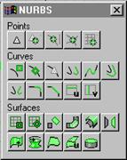
The toolbox contains buttons for creating NURBS sub-objects. From a curve object, you can create points or other curves. From a surface object, you can create points, curves, or other surfaces. In general, the toolbox behaves like this:
While the button is turned on, the toolbox is visible whenever a NURBS object or sub-object is selected and you are in the Modify panel. It disappears whenever you deselect the NURBS object or make a different panel active. When you return to the Modify panel and select a NURBS object, it reappears.
You can use the toolbox to create sub-objects either at the top, object level or at any NURBS sub-object level.
When you turn on a toolbox button, you go into creation mode, and the Modify panel changes to show the parameters (if there are any) for the kind of sub-object you are creating.
If you are at the top, object level and use the toolbox to create an object, you must then turn on Sub-Object to edit the new sub-object. (This is no different from using the buttons in the rollouts.)
If you are at a sub-object level and use the toolbox to create an object of the same sub-object type, you can edit it immediately after you turn off the create button (or right-click).
If you are at a sub-object level and use the toolbox to create an object of a different sub-object type, you must use the drop-down to change the sub-object level before you can edit the new sub-object.
The individual creation buttons are described in the appropriate sections below: "Using Points," "Creating Dependent Curves," and "Creating Dependent Surfaces."
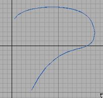
NURBS curves are Shape objects, and you can use them as you do splines. You can use the Extrude or Lathe modifiers to generate a 3D surface based on a NURBS curve. You can use NURBS curves as the path or the shape of a Loft. (Lofts created using NURBS Curves are loft objects, not NURBS objects).
You can also use NURBS curves as Path Controller paths or motion trajectories.
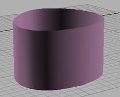
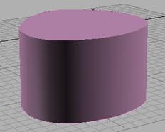
You can give a NURBS curve a thickness so it renders as a cylindrical object. (The thickened curve renders as a polygonal mesh, not as a NURBS surface.)
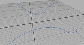
A curve and the same curve rendered with thickness
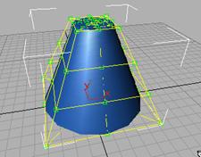
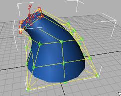
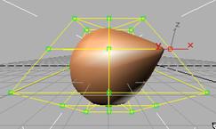
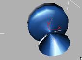
CV Curves and CV Surfaces have control vertices as splines do. The position of the control vertices (CVs) controls the shape of the curve or the surface. However, unlike spline vertices, CVs don't necessarily lie on the curve or surface they define. The CVs define a control lattice. The control lattice connects the CVs. 3DS MAX displays it in dashed yellow lines. The control lattice surrounds the NURBS curve or surface.
|
|
Cone-shaped NURBS surface with its control lattice (CVs are displayed as green squares)
Tip: When you use Zoom Extents, 3DS MAX R2 Beta displays the entire extents of a NURBS object, including its control lattice. Because CVs can be at some distance from an object, sometimes this makes the curve or surface itself (the object's renderable geometry) hard to see. Use Zoom Region or Field of View to zoom in on the object's renderable geometry.
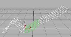
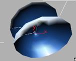
You can move CVs at the Curve CV or Surface CV sub-object level in the Modify command panel. Other transforms rotate and scale work as well. Rotate and scale are especially useful when you have selected multiple CVs.
Moving and rotating CVs to change a surface (selected CVs displayed in red)
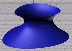
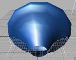
Each CV also has a weight, which you can use to adjust the CV's effect on the curve or surface. Increasing the weight pulls the surface towards the CV. Decreasing the weight relaxes the surface away from the CV.
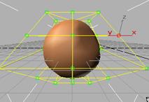
Weight = 0.0 Weight = 10.0
Changing a spherical surface by decreasing or increasing the weight of one CV (selected CV at the right, in red)
Weights can be a useful way to "tune" the appearance of a NURBS curve or surface.
The weight value of a CV is rational. That is, it is relative to other CVs in the curve or surface. Changing the weight of all CVs at once has no effect, because this doesn't change the ratio between weights.
Point Curves and Point Surfaces are similar to CV Curves and Surfaces, but the points that control them are required to lie on the curve or surface. Unlike CVs, points do not have a weight.
Point Curves and Point Surfaces can be more intuitive to create and work with. However, they can give you unexpected results, because more than one NURBS solution is possible for a given set of NURBS points. This is not true of CV Curves and Surfaces, which fully define their object.
Points that you create individually are the same as the points on Point Curves and Surfaces, except that they aren't (initially) part of a curve or surface. You can create a Point Curve by fitting it to points that you select. You can use both points that are part of curves or surfaces, and individual point sub-objects, when you fit the new Point Curve.
When you work with NURBS models, you often work with sub-objects. While you are at the sub-object level, you use the usual 3DS MAX selection techniques, such as clicking or dragging a region, or holding down CTRL, to choose one or more sub-objects. You can also select NURBS sub-objects by name. Turn on the Plug-In Keyboard Shortcut Toggle button in the status bar, and then press the "H" key. This displays a select-by-name dialog that lists only sub-objects at the current level. Choose one or more objects in the list, and then click Select. This dialog is especially useful at the Curve and Surface sub-object levels. The large number of CVs or points in a complicated curve or surface makes them harder to distinguish by name but you can assign your own names to NURBS sub-objects you want to edit frequently.
Tips: When you work with NURBS, often you switch frequently between the object and sub-object levels, or from one sub-object level to another. Two keyboard shortcuts can help you do this. The Sub-Object Selection Toggle (default = CTRL + B) switches between object and sub-object levels. The Cycle Sub-Object Level shortcut (default: INSERT) switches from one sub-object level to another. Also, the command panel's right-click popup menu (available whenever the pan hand is visible) helps you navigate the rollouts in the current command panel.
NURBS sub-objects are either independent or dependent. A dependent sub-object is one based on the geometry of other sub-objects. For example, a Blend surface smoothly connects two other surfaces. Transforming or animating either of the original, parent surfaces causes the shape of the Blend to change, as it maintains a connection between the parents.
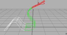
Moving a parent surface changes the blend surface (the blend surface is displayed in green)
This immediate, interactive relation between the parent and dependent sub-objects is known as relational modeling. Relational modeling is one of the reasons NURBS models can be particularly easy to change or to animate.
Important: Dependent sub-objects must have parents who are also sub-objects of the same NURBS model. Dependent relationships can't exist between object-level NURBS curves or surfaces. If you want to use a top-level NURBS object to create a dependent object, first you must attach or import the top-level object. See "Attaching and Importing 3D Studio MAX Objects."
You have the option of making a dependent sub-object independent. After you do so, the sub-object is no longer related to its parents. Changes to the former parents don't affect it, but you can directly edit and transform it as an independent sub-object in its own right.
At the appropriate sub-object level, dependent NURBS are displayed in green in wireframe viewports (you can change the display color using the Colors panel of the Edit/Preferences dialog).
Sometimes changes you make to the parent objects make it no longer possible to correctly update the dependent object's geometry. For example, a Fillet between two curves requires the curves to be coplanar. If you move one curve (or its CVs or points) so that the curves are no longer coplanar, 3DS MAX cannot correctly update the Fillet. In this case, the dependent object's geometry does not change, and 3DS MAX displays it in orange to indicate that it has an error condition. (You can change the error color using the Colors panel of the Edit/Preferences dialog.)
Transforming Dependent Sub-Objects
In general, you can select and transform dependent sub-objects, but the effect of the transform depends on the sub-object type. Sub-objects that don't have gizmos can't change relative to their parent objects. For these kinds of sub-objects, transforms apply equally to the sub-object and its parents. For example, moving a blend sub-object moves its parents as well. Sub-objects that have gizmos can change relative to their parent objects. In this case, as with modifiers that use gizmos, you are really transforming the gizmo. For example, rotating a mirror sub-object changes the mirror axis, and therefore the mirror's position relative to the parent curve or surface.
In general, you can apply modifiers to NURBS models as you do to other 3DS MAX objects. The exceptions are the edit modifiers that apply to meshes and patch surfaces. These don't apply to NURBS objects, and are disabled when a NURBS object is selected.
Deform modifiers such as Bend and Twist operate on CV and point sub-objects. They don't change the NURBS model into an editable mesh object. This means that you can use a deform modifier, collapse the stack, and still have a NURBS object that you can edit further. However, because the deform modifiers directly affect CVs and points, not the mesh approximation of the NURBS model, they can produce unexpected results. For example, a Ripple modifier does not ripple the surface if the CVs are farther apart than the wavelength of the ripples. If you want the modifier to affect the mesh approximation instead of the CVs, you can apply a Mesh Select modifier first. Then when you collapse the stack, you get an editable mesh, not a NURBS object.
When you apply a UVW Map modifier, it affects the NURBS object the same way it affects a mesh. If you then collapse the stack, the modifier is still in effect. However, you can override the mapper for individual surface sub-objects. To do so, turn on the surface's Generate Mapping Coords. check box. When the check box is on, you get the natural mapping of the surface; when it is off, you get the mapping from the collapsed UVW modifier.
In general, you can animate NURBS Curves and NURBS Surface by turning on the Animate button and transforming sub-object attributes such as CV or point positions, by animating the parameters that control dependent NURBS objects, and so on. You can't animate NURBS object creation or creation parameters, or fundamental changes to NURBS geometry such as adding or deleting CVs or points, attaching objects, and so on.
These are mentioned where they arise throughout the document, but in general the following operations are the ones that remove animation:
Make Independent
Removes the animation of anything directly dependent on the object.
Break, Extend, Join, Refine, and Delete
Any operation that changes the number of points or CVs in a curve or surface
loses the animation on all points or CVs to be lost.
Fuse
The animation of the point or CV being fused to the other point or CV (the
second one chosen) is lost. The first point or CV acquires the animation of the
second.
NURBS curves and surfaces did not exist in the conventional drafting world. They were created specifically for 3D modeling using computers. Curves and surfaces represent contours or shapes within a 3D modeling space. They are constructed mathematically. NURBS mathematics is complex, and this section is simply an introduction to some NURBS concepts that might help you understand what you are creating, and why NURBS objects behave as they do. For a comprehensive description of the mathematics and algorithms involved in NURBS modeling, see The NURBS Book by Les Piegl and Wayne Tiller (New York: Springer, second edition 1997).
The term NURBS stands for Non-Uniform Rational B-Splines. Specifically:
A B-spline (for basis spline) is a way to construct a curve that is interpolated between three or more points.
Shape curves you create in 3DS MAX using the Line tool and other Shape tools are Bézier curves, which are a special case of B-splines.
Rational means that the equation used to represent the curve or surface is expressed as a ratio of two polynomials, rather than a single summed polynomial. The rational equation provides a better model of some important curves and surfaces, especially conic sections, cones, spheres, and so on.
Non-Uniform means that the extent of a control vertex's influence can vary. This is useful when modeling irregular surfaces. Also, uniform curves and surfaces aren't invariant under perspective projection a serious limitation for interactive 3D modeling.
The non-uniform property of NURBS brings up an important point. Because they are generated mathematically, NURBS objects have a parameter space in addition to the 3D geometric space in which they are displayed. Specifically, an array of values called knots specifies the extent of influence of each control vertex (CV) on the curve or surface. Knots are invisible in 3D space and you can't manipulate them directly, but occasionally their behavior affects the visible appearance of the NURBS object. This section mentions those situations. Parameter space is one-dimensional for curves, which have only a single U dimension topologically, even though they geometrically exist in 3D space. Surfaces have two dimensions in parameter space, called U and V.
NURBS curves and surfaces have the important properties of not changing under the standard geometric affine transformations (Transforms in 3DS MAX), or under perspective projections. The CVs have local control of the object moving a CV or changing its weight does not affect any part of the object beyond the neighboring CVs. (In 3DS MAX, you can override this property by using the Affect Region controls.) Also, the control lattice that connects CVs surrounds the surface. This is known as the convex hull property.
All curves have a degree. The degree of a curve is the highest exponent in the equation used to represent it. A linear equation is degree 1, a quadratic equation degree 2. NURBS curves typically are represented by cubic equations and have a degree of 3. Higher degrees are possible but usually unnecessary.
Curves also have continuity. A continuous curve is unbroken. There are different levels of continuity. A curve with an angle or cusp in it is C continuous that is, the curve is continuous but has no derivative at the cusp. A curve with no such cusps but whose curvature changes is C continuous. Its derivative is also continuous, but its second derivative is not. A curve with uninterrupted, unchanging curvature is C continuous. Both its first and second derivatives are also continuous.
[ADD ILLUSTRATION]
A curve can have still higher levels of continuity, but for computer modeling these three are adequate. Usually the eye can't distinguish between a C continuous curve and one with higher continuity.
Continuity and degree are related. A degree 3 equation can generate a C continuous curve. This is why higher-degree curves aren't generally needed in NURBS modeling. Higher-degree curves are also less stable numerically, so using them isn't recommended.
Different segments of a NURBS curve can have different levels of continuity. In particular, by placing CVs at the same location or very close together, you reduce the continuity level. Two coincident CVs sharpen the curvature. Three coincident CVs create an angular cusp in the curve. This property of NURBS curves is known as multiplicity. In effect, the additional one or two CVs combine their influence in that vicinity of the curve.
[ADD ILLUSTRATION]
By moving one of the CVs away from the other, you increase the curve's continuity level again. In 3DS MAX, multiplicity also applies when you fuse CVs. Fused CVs create a sharper curvature or a cusp in the curve. Again, the effect goes away if you unfuse the CVs and move one away from the other.
Refining a NURBS curve means to add more CVs. Refining gives you finer control over the shape of the curve. When you refine a NURBS curve in 3DS MAX, the software preserves the original curvature. (Technically speaking, it maintains a uniform knot vector.) In other words, the shape of the curve doesn't change, but the neighboring CVs move away from the CV you add. This is because of multiplicity if the neighboring CVs didn't move, the increased presence of CVs would sharpen the curve. With the 3DS MAX interface, you first refine the curve, then change it by transforming the newly added CVs, or adjusting their weights.
[ADD ILLUSTRATION]
NURBS surfaces have essentially the same properties as NURBS curves, extended from a one-dimensional parameter space to two dimensions.
In 3DS MAX you can work with point curves and point surfaces as well as CV curves and surfaces. The points that control these objects are constrained to lie on the curve or surface. There is no control lattice, and no weight control. This is a simpler interface that some users find easier to work with. Also, point-based objects give you the ability to construct curves based on dependent (constrained) points, and then use these to construct dependent surfaces.
You think of point curves and surfaces as an interface to CV curves and surfaces, which are the fully defined NURBS objects. The underlying representation of the curve or surface is still constructed using CVs. There can be more than one CV solution for a point curve or surface because of this, occasionally 3DS MAX might construct a point curve or surface in a way you didn't expect.
You can also think of a point curve or surface as dependent
on its points. You can use the Make Independent button to convert a point curve
or surface to the CV form. On the other hand, you can't convert from the CV to
the point form, because there are multiple point solutions for a single CV
curve or surface.
You create NURBS curve objects in the Create command panel.
To create a NURBS curve:
![]() Go to the Create command panel and
Go to the Create command panel and ![]() turn on Shapes.
turn on Shapes.
Choose NURBS Curves from the dropdown list.
Turn on Point Curve or CV Curve.
In a viewport, click and drag to create the first point or CV, as well as the first curve segment. Release the mouse to add the second point or CV. Each subsequent location you click adds a new point or CV to the curve. Right-click to end curve creation.
Note: If you begin the curve by clicking without dragging, this also creates the curve's first point or CV. However, if you release the mouse more than five pixels away from where you initially pressed it, this creates an additional point or CV.
While you are creating a NURBS curve of either type, you can press BACKSPACE to remove the last point or CV you created, and then previous points or CVs in reverse order.
As with splines, if you right-click over the curve's initial point or CV, a dialog appears asking whether you want the curve to be closed. Click No to leave the curve open, Yes to close the curve. (You can also close a curve when you edit it at the Curve sub-object level.) When a closed curve is displayed at the Curve sub-object level, the initial point or CV is displayed as a green circle, and a green tick mark indicates the curve's direction.
6. Adjust the curve's creation parameters. These are described below.
7. (Optional.) To add a new NURBS curve sub-object, you can turn off the Start New Shape check box, and then repeat the preceding steps.
While you're creating a CV Curve not a Point Curve you can click to create more than one CV at the same location (or close to it), increasing the influence of the CVs in that region of the curve. Creating two coincident CVs can sharpen the curvature. Creating three coincident CVs can create an angular corner in the curve. This technique can help you shape the curve however, if you later move the CVs individually, you lose this effect. (You can also obtain the influence of multiple CVs by fusing CVs, as described in "Fusing Points or CVs" under "Point and CV Sub-Object Controls," below.)
Tip:
Object-level NURBS curves can't contain surface sub-objects, so you can't use
them as the basis for a full NURBS model. But you can convert the curve object
to a NURBS surface object using the Edit Stack button in the Modify panel.
The creation parameters are the same for both Point Curves and CV Curves.
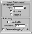
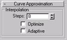
Interpolation
The controls in this area change the accuracy and kind of approximation used to generate and display the curve. See the section "Curve Approximation," below.
Rendering Controls
You can make curves renderable by assigning them a thickness with these controls. The curve renders as a cylindrical object. Renderable NURBS curves appear when you render a scene using Render; they are not rendered in shaded viewports.
Renderable: Turn on to make the curve renderable.
Thickness: Sets the renderable thickness of the curve its circular diameter using the current 3DS MAX units.
Generate Mapping Coordinates: Generates mapping coordinates so you can apply mapped materials to the renderable curve.
The Keyboard Entry rollout lets you create a NURBS curve by typing. Use the TAB key to move between the controls in this rollout. To press a button, use ENTER while the button is active.
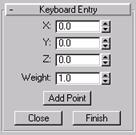
X, Y, and Z: Enter the coordinates of the next point or CV to add.
Weight: Enter the weight of the CV. This field is not present for Point Curves.
Add Point: Adds the point or CV to the curve.
Close: Ends creation of the curve and creates a segment between the last point or CV and the initial point or CV, to make the curve a closed curve.
Finish: Ends creation of the curve, leaving it open ended.
You create NURBS surface objects in the Create command panel. The initial surface is a planar segment with points or CVs. It is meant simply as "raw material," an easy way to begin creating a NURBS model. Once you have created the initial surface, you can modify it in the Modify command panel by moving CVs or NURBS points, attaching other objects, creating sub-objects, and so on.
Because an initial NURBS surface is meant to be edited, the surface creation parameters do not appear in the Modify command panel. In this respect, NURBS surface objects are different from other 3DS MAX objects. The Modify command panel provides other ways to change the values you set in the Create panel.
To create a NURBS surface:
![]() Go to the Create command panel and
Go to the Create command panel and ![]() turn on Geometry.
turn on Geometry.
2. Choose NURBS Surfaces from the dropdown list.
3. Turn on Point Surf or CV Surf.
4. In a viewport, drag to specify the area of the planar segment.
5. Adjust the surface's creation parameters. These are described below.
The creation parameters are the same for both Point Surfaces and CV Surfaces, except that the labels indicate which kind of basic NURBS surface you are creating.
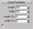
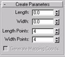
Length: The length of the surface, in current 3DS MAX units.
Width: The width of the surface, in current 3DS MAX units.
In the Modify command panel, the Length and Width spinners are no longer available. You can change the length or width of the surface by scaling the surface at the Surface sub-object level. Moving CV or point sub-objects also alters the length and width of the surface.
Length CVs or Length Points: The number of CVs or points along the length of the surface. In other words, the initial number of CV or point columns in the surface. Can range from 4 to 50.
Width CVs or Width Points: The number of CVs or points along the width of the surface. In other words, the initial number of CV or point rows in the surface. Can range from 4 to 50.
In the Modify command panel, the CV and point Length and Width spinners are no longer available. You can change the number of rows and columns by deleting existing rows and columns, or by adding new rows and columns using the Refine controls at the Surface CV or Point sub-object level.
Generate Mapping Coordinates: Generates mapping coordinates so you can apply mapped materials to the surface.
The Generate Mapping Coordinates control is present in the Modify command panel. It is at the Surface sub-object level.
The Keyboard Entry rollout lets you create a NURBS surface by typing. Use the TAB key to move between the controls in this rollout. To press the Create button, use ENTER while the button is active.
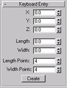
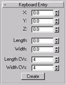
X, Y, and Z: Enter the coordinates of the center of the surface.
Length and Width: Enter the dimensions of the surface, in current 3DS MAX units.
Length CVs or Length Points: Enter the number of CVs or points along the length of the surface (this is the initial number of CV or point columns).
Width CVs or Width Points: Enter the number of CVs or points along the width of the surface (this is the initial number of CV or point rows).
Create: Creates the surface object.
You can turn a 3DS MAX Standard Primitive into a NURBS object formed of CV surfaces. (You can't convert Extended Primitive objects in this way.) Once converted, you can no longer edit the object parametrically, but you can edit it as a NURBS object, moving CVs and so on.
To turn a primitive into a NURBS object:
Create the primitive object.
![]() Go to the Modify command panel.
Go to the Modify command panel.
![]() In the Modifier Stack rollout, click Edit
Stack.
In the Modifier Stack rollout, click Edit
Stack.
Choose NURBS Surface from the pop-up menu that appears.
The object is converted to one or more CV surfaces that you can edit.
Tips:
Sometimes converting the primitive to a NURBS object causes its normals to point the wrong way. You can see this in shaded viewports. If this happens, turn on Flip Normals at the Surface sub-object level.
Geospheres are good for creating rounded models with no sharp edges.
Boxes are good for creating models that have sharp edges.
Flattened cones work well for models whose contours are roughly triangular.
There are two ways to bring other 3DS MAX objects into a NURBS object:
Attach, which works like Attach for meshes and splines. It converts the attached object to NURBS format. Once the object is attached, you can edit it as a NURBS surface or curve. However, the attached object's history is lost.
Note: For NURBS surfaces, you can attach other NURBS objects, 3DS MAX Standard Primitive objects, Quad Patch and Tri Patch surfaces, or objects with an Edit Patch modifier applied to them. The patch is converted to a NURBS surface. Quad patches convert more successfully than Tri Patches. A converted Tri Patch has an internal edge collapsed, which gives irregular results when you manipulate its mesh.
Import, which works somewhat like the operand of a Boolean. The object is brought into the NURBS object without losing its history. You can select the imported object as a sub-object, and edit its history using the Modifier stack.
To attach or import an object to a NURBS object:
![]() Select the NURBS object, and go to the
Modify command panel.
Select the NURBS object, and go to the
Modify command panel.
(Optional.) Turn on Reorient if you want the object to be reoriented and aligned with the center of the NURBS object.
Turn on Attach or Import.
Click the object to attach or import.
The mouse cursor changes shape to indicate a valid object. If you are editing a NURBS curve, you can attach only NURBS or spline curves. If you are editing a NURBS surface, you can attach curves, NURBS surfaces, or objects convertible to NURBS.
At step 3, you can click Attach Multiple or Import Multiple instead. These buttons display a select-by-name dialog so you can choose multiple objects to attach or import.
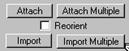
Attach and Import controls
Attach: Lets you attach another object to the NURBS object. To use, click to turn on this button, and then click the object to attach If the object you're attaching isn't already a NURBS object, it is converted to one or more NURBS curves or surfaces that are sub-objects of the object you're modifying.
Attach Multiple: Lets you attach multiple objects to the NURBS surface. Displays a version of the Select by Name dialog, listing the objects that can be attached. Use the dialog controls to select one or more objects by name, and then click Attach.
Reorient: When turned on, the object you are attaching or importing is moved and rotated so its creation local coordinate system is aligned with the creation local coordinate system of the NURBS object.
Import: Lets you import another object to the NURBS object. Works the same way Attach does, but the imported object retains its parameters and modifiers.
Import Multiple: Lets you import multiple objects. Works the same way Attach Multiple does, but the imported objects retains their parameters and modifiers.
There are several reasons to use Import instead of Attach:
To maintain parametric control over primitives.
For example, if you import a sphere, you can change or animate its radius directly, which you can't do after an attach.
To use Bézier Splines as NURBS curves.
For example, If you want to use a 3DS MAX Bézier spline as a curve in a NURBS model, import it. This allows you to edit it as a Bézier Spline, not as a NURBS curve.
To use the Modifier stack as a modeling tool. Probably this is the most useful reason for imports.
For example, you can import another object (or a NURBS surface) and use deform modifiers such as Twist and Bend to change its shape. Then you can use the resulting surface as a NURBS sub-object, creating Blends between it and other surfaces, and using other tools available to NURBS objects.
All the surfaces and curves that are created by an import are available in the NURBS model. For example, if you import a box, you can create a blend surface between one of its faces and another surface in your NURBS object.
Once you have imported an object, you see an "Imports" entry in the list of sub-object levels. On entering the Imports level, all objects that aren't Imports are displayed in a dimmed color. This lets you know which objects you can select at this level. When you select an import, it is highlighted in red. Import sub-objects have a red highlight even in shaded viewports, unlike other types of 3DS MAX sub-objects.
After you choose Imports as the sub-object level and then select an imported object, the import's history is available on the Modifier stack. (This is like working with the selected operand of a Boolean.) You can use the stack to edit modifier settings, add or remove modifiers, and change the import's creation parameters. While you edit the imported object, the NURBS model updates any curves or surfaces that are dependent on the import.
Caution: By applying modifiers to an import, it is possible to change its type to something that can't be converted into a NURBS object. For example, if you import a box, then put a bend on it, the box becomes a mesh, which can't convert to a NURBS object. When this happens, the object [disappears from the NURBS object; in the future, there will be an error representation as there is for dependent sub-objects].
Imports are displayed in two different ways. While you work at the NURBS object level or other sub-object levels, they are displayed as NURBS curves or surfaces, and use the NURBS object's mesh tessellation. (See the selection "Surface Approximation," below.) However, at the Imports sub-object level, 3DS MAX displays the selected import using its native display format. In other words, displays as it would if it were a top-level 3DS MAX object. This is because the display must enable you to edit the imported object. For example, an imported Bézier spline needs to display its tangent handles. This wouldn't be possible if it were displayed as a converted NURBS curve. Leaving the Imports sub-object level returns to NURBS-style display.
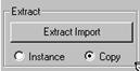
To extract an imported object, click Extract Import in the Import sub-object rollout. If Copy is set (the default), the extracted object is a top-level copy of the imported object. If Instance is set, the extracted object is an instance of the imported object. Initially the extracted object occupies the same space as the imported object you must move either it, the import sub-object, or the whole NURBS model before you can see the extracted object.
Dependent curves are curve sub-objects whose geometry depends on other curves or points in the NURBS object. When you change the geometry of the original, parent sub-objects, the dependent curve changes as well.
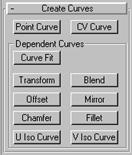
You create dependent curves using the Create Curves rollout in the Modify command panel for a NURBS curve. (The Point Curve and CV Curve buttons create independent curve sub-objects. Use these as previously described in "Creating NURBS Curves.") The remaining buttons create dependent curves, as described in the sections below.
Tip: Loft and extrude surface sub-objects can be based on only a single curve (see "Creating Dependent Surfaces," below). If you create dependent curves and then want to use the set of curves (for example, two parents and a fillet between them) as the basis of an extrude or loft surface, first go to the Curve sub-object
level and use Join to connect the curves.
These are the toolbox buttons for creating curve sub-objects:
|
|
Create an independent CV curve.
|
|
Create an independent point curve.
|
|
Create a dependent fit curve (as with the Curve Fit button).
|
|
Create a dependent transform curve.
|
|
Create a dependent blend curve.
|
|
Create a dependent offset curve.
|
|
Create a dependent mirror curve.
|
|
Create a dependent fillet curve.
|
|
Create a dependent chamfer curve.
|
|
Create a dependent U iso curve.
|
|
Create a dependent V iso curve.
Creates a Point Curve fitted to points you select. The points can be part of previously created Point Curve and Point Surface objects, or point sub-objects you created explicitly. They can't be CVs.
To create a Point Curve with Curve Fit:
Turn on Curve Fit.
Click to select two or more points.
3DS MAX creates a point curve that runs through the points you select, in the order you select them.
Right-click to end creation.
A transform curve is a copy of the original curve that you can change using position, rotation, or scale transforms.
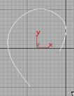
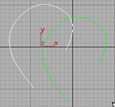
Curve used to create a transform curve
To create a transform curve:
In a NURBS object that contains at least one curve, turn on Transform.
To move the transform curve, click and drag the curve you want to duplicate. To rotate or scale the transform curve, click the parent curve, click to turn on Sub-Object in the Modifier Stack rollout, choose Curve from the dropdown list, and then use a transform to rotate or scale the transform curve.
When you use Move to create the transform curve, it simply copies the parent (it doesn't exaggerate curvature as an offset curve does.)
Transform curves have no special Parameters rollout. You can later transform the transform curve as a Curve sub-object, and you can animate Curve sub-object transforms.
A blend curve connects the end of one curve to the end of another, blending the curvature of the parents to create a smooth curve between them. You can blend curves of the same type, or a Point Curve with a CV curve (and vice versa).
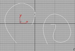
Connecting two curves with a blend curve
To create a blend curve:
In a NURBS object that contains two curves of the same type (Point or CV), turn on Blend.
Click one curve near the end that you want to connect. The end that will be connected highlights. Without releasing the mouse, drag to the end of the other curve that you want to connect. The other end highlights as well. When the end that you want to connect is highlighted, release the mouse.
After the blend curve is created, changing the position or the curvature of either parent curve changes the blend curve as well.
3. Adjust the blend parameters. These are described below.
When you turn on the Blend button, or while a blend curve sub-object is selected, a rollout with the blend parameters appears.

"Tension" affects the tangent between a parent curve and the blend curve. The greater the tension value, the more closely the tangent parallels the parent curve, and the smoother the transition. The lower the tension, the greater the tangent angle and the sharper the transition between parent and blend.
Tension 1: Controls tension at the edge of the first surface you clicked.
Tension 2: Controls tension at the edge of the second surface you clicked.
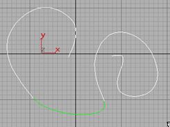
An Offset is offset from the original, parent curve. It lies in the same plane as its parent, and is normal to the original.
Curve used to create an offset curve
To create an offset curve:
In a NURBS object that contains at least one curve, turn on Offset.
Click the curve you want to offset, and drag to set the initial distance.
3DS MAX creates the offset curve.
Adjust the Distance parameter.
If the parent curve is not linear, increasing the distance increasingly exaggerates the curvature of the offset curve.
When you turn on the Offset button, or while an offset curve sub-object is selected, a rollout with the offset Distance parameter appears.
![]()
Distance: The distance between the parent curve and the offset curve, in 3DS MAX units.
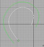
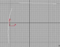
A mirror curve is similar to a mirror object that you create using the Mirror tool (on the toolbar) or the Mirror modifier.
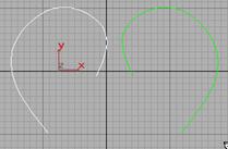
Curve used to create a mirror curve
To create a mirror curve:
In a NURBS object that contains at least one curve, turn on Mirror.
In the Mirror Curve rollout (see below), choose the axis or plane you want to use.
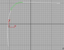
Click the curve you want to mirror, and drag to set the initial distance.
3DS MAX creates the mirror curve. A black gizmo indicates the direction of mirroring transforming the mirror curve's gizmo changes the orientation of the mirror, letting you mirror along an axis that isn't aligned with a local coordinate axis.
4. Adjust the Offset parameter.
When you turn on the Mirror button, or while a mirror curve sub-object is selected, a rollout with the mirror parameters appears.
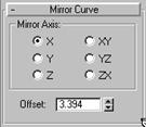
The Mirror Axis buttons control the direction in which the original curve is mirrored. The Offset controls the mirror's distance from the original curve. This parameter is animatable.
You can transform a mirror curve as you do a transform curve sub-object. Using transforms lets you mirror about an arbitrary axis, rather than one of the Mirror Axis presets. When you transform a mirror curve, you are actually transforming the mirror plane, so Rotate has the effect of rotating the plane about which the curve is mirrored. (This is like rotating the mirror gizmo in the Mirror modifier.)
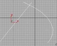
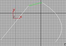
Fillet creates a curve that is a rounded corner between two parent curves.
Fillet connecting two curves
To create a fillet curve:
In a NURBS object that contains at least one curve, turn on Fillet.
Click one curve near the end that you want to connect. The end that will be connected highlights. Without releasing the mouse, drag to the end of the other curve that you want to connect. When the end that you want to connect is highlighted, release the mouse.
3DS MAX creates the fillet curve, trimming the ends of the parent curve to match the fillet. The fillet is not necessarily placed at the endpoints of the parent curves this depends on the value of the Radius parameter, described below.
Changing the position or the curvature of either parent curve can change the fillet as well.
The parent curves must be coplanar.
Adjust the fillet parameters, described below.
When you turn on the Fillet button, or while a fillet curve sub-object is selected, a rollout with the fillet parameters appear.
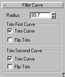
Radius: The radius of the fillet arc, in the current 3DS MAX units. Default = 10.0.
Tip: If the fillet you initially create is in an error state it appears as a straight line in the error color (orange by default) often this is because the radius is not large enough to bridge the distance between the two curves. Increasing the Radius value gives you a correct fillet. The fillet becomes an arc displayed in the dependent object color (green by default).
Trim First Curve and Trim Second Curve
These two areas let you control how the parent curves are trimmed. The controls are the same in each. "First" and "second" refer to the order in which you picked the parent curves.
Trim Curve: When on (the default), trims the parent curve against the fillet curve. When off, the parent isn't trimmed.
Flip Trim: When on, trims in the opposite direction.
Chamfer creates a curve that is a straight bevel between two parent curves.
Chamfer connecting two curves
To create a chamfer curve:
In a NURBS object that contains at least one curve, turn on Chamfer.
Click one curve near the end that you want to connect. The end that will be connected highlights. Without releasing the mouse, drag to the end of the other curve that you want to connect. When the end that will be connected is highlighted, release the mouse.
3DS MAX creates the chamfer curve. Changing the position or the curvature of either parent curve can change the chamfer as well.
The parent curves must be coplanar. The chamfer is not necessarily connected at the endpoints of the parent curves you can adjust its position with the chamfer's Length parameters.
Adjust the chamfer parameters, described below.
When you turn on the Chamfer button, or while a chamfer curve sub-object is selected, a rollout with the Chamfer parameters appear.
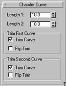
The lengths are the distance from the intersection (or apparent intersection) at which the chamfer segment is drawn.
Length 1: The distance along the first curve you click.
Length 2: The distance along the second curve you click.
Some length values make it impossible to construct the chamfer. If you set the length to an invalid value, the chamfer returns to a default position and displays in the error color (orange by default).
Trim First Curve and Trim Second Curve
These two areas let you control how the parent curves are trimmed. The controls are the same in each. "First" and "second" refer to the order in which you picked the parent curves.
Flipping the direction of a trim
Trim Curve: When on (the default), trims the parent curve against the fillet curve. When off, the parent isn't trimmed.
Flip Trim: When on, trims in the opposite direction.
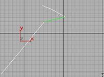
U and V iso curves are dependent curves created from the iso (isoparametric) lines of a NURBS surface.
To create an iso curve:
Turn on U Iso Curve or V Iso Curve, then drag over the surface.
The iso lines highlight in blue as you drag.
Click to create the curve from the highlighted iso line.
When you turn on the U Iso or V Iso button, or while an iso curve sub-object is selected, a rollout with the Iso Curve parameters appears.
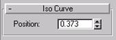
Position: Sets the iso curve's position along the U or V axis of the surface. This parameter is animatable.
Dependent surfaces are surface sub-objects whose geometry depends on other surfaces or curves in the NURBS model. When you change the geometry of the original, parent surface or curve, the dependent surface changes as well.
You create dependent surfaces using the Create Surfaces rollout in the Modify command panel for a NURBS surface. (The Point Surf and CV Surf buttons create independent surface sub-objects. Click one of these buttons and then drag in a viewport to create the surface, as previously described in "Creating NURBS Surfaces.")
Tip: Loft and extrude surface sub-objects can be based on only a single curve. If you have dependent curves and want to use the set of curves (for example, two parents and a fillet between them) as the basis of an extrude or loft surface, first go to the Curve sub-object level and use Join to connect the curves.
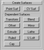
These are the toolbox buttons for creating surface sub-objects:
|
|
Create an independent CV surface.
|
|
Create an independent point surface.
|
|
Create a dependent transform surface.
|
|
Create a dependent blend surface.
|
|
Create a dependent offset surface.
|
|
Create a dependent mirror surface.
|
|
Create a dependent extrude surface.
|
|
Create a dependent lathe surface.
|
|
Create a dependent ruled surface.
|
|
Create a dependent U Loft surface.
![]() Create a dependent cap surface.
Create a dependent cap surface.
A transform surface is a copy of the original surface that you can change using position, rotation, or scale transforms.

Surface created as a transform
To create a transform surface:
In a NURBS object that contains at least one surface, turn on Transform.
To move the transform surface, click and drag the surface you want to duplicate. To rotate or scale the transform surface, click the parent surface, click to turn on Sub-Object in the Modifier Stack rollout, choose Surface from the dropdown list, and then use a transform to rotate or scale the transform surface.
When you use Move to create the transform surface, it simply copies the parent (it doesn't exaggerate curvature as an offset surface does).
There is no special parameter rollout for transform surfaces. You can later transform the transform surface as a Surface sub-object, and you can animate Surface sub-object transforms.
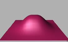
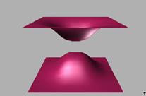
A blend surface connects one surface to another, blending the curvature of the parent surfaces to create a smooth surface between them.
Blend surface connecting two other surfaces
To create a blend surface:
In a NURBS object that contains two surfaces, turn on Blend.
Click one surface near the edge that you want to connect. The edge that will be connected is highlighted in blue. Drag to choose the edge you want to connect. Without releasing the mouse, drag to the other surface. The edge of the other surface is also highlighted in blue. Drag on the other surface to choose the edge to connect, and then release the mouse.
3DS MAX creates the blend surface. Changing the position or the curvature of either parent surface will change the blend surface as well.
3. Adjust the blend parameters. These are described below.
When you turn on the Blend button, and while a blend surface sub-object is selected, a rollout with the blend parameters appears at the bottom of the command panel

"Tension" affects the tangent between a parent surface and the blend surface. The greater the tension value, the more closely the tangent parallels the parent surface, and the smoother the transition. The lower the tension, the greater the tangent angle and the sharper the transition between parent and blend.
Tension 1: Controls tension at the edge of the first surface you clicked.
Tension 2: Controls tension at the edge of the second surface you clicked.
Flip End 1 and Flip End 2: Flip one of the normals used to construct the blend. A blend surface is created using the normals of the parent surfaces. If the two parents have opposing normals, this can lead to a blend surface shaped like a bow tie. To correct the situation, use Flip End 1 or Flip End 2 to have the blend constructed using a normal opposite the corresponding parent surface's normal.
An Offset surface is offset a specified distance from the original along the parent surface's normals.

Surface created as an offset
To create an offset surface:
In a NURBS object that contains at least one surface, turn on Offset.
Click the surface you want to offset, and drag to set the initial distance.
3DS MAX creates the offset surface.
Adjust the Distance parameter.
If the parent surface is planar, the appearance of the offset surface doesn't change with distance. If the parent surface is curved, increasing the distance increasingly exaggerates the curvature of the offset surface.
When you turn on the Offset button, and while an offset surface sub-object is selected, a rollout with the offset Distance parameter appears at the bottom of the command panel.
![]()
Distance: The distance between the parent surface and the offset surface, in 3DS MAX units.
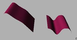
A mirror surface is similar to a mirror object that you create using the Mirror tool (on the toolbar) or the Mirror modifier.
Surface created as a mirror (about the Z axis)
To create a mirror surface:
In a NURBS object that contains at least one surface, turn on Mirror.
In the Mirror Surface rollout (see below), choose the axis or plane you want to use.
Click the surface you want to mirror, and drag to set the initial distance.
3DS MAX creates the mirror surface. A black gizmo indicates the direction of mirroring transforming the mirror surface's gizmo changes the orientation of the mirror, letting you mirror along an axis that isn't aligned with a local coordinate axis.
4. Adjust the Offset parameter.
When you turn on the Mirror button, or while a mirror surface sub-object is selected, a rollout with the mirror parameters appears.
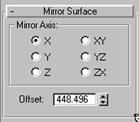
The Mirror Axis buttons control the direction in which the original surface is mirrored. The Offset controls the mirror's distance from the original surface. This parameter is animatable.
You can transform a mirror surface as you do a transform surface sub-object. Using transforms lets you mirror about an arbitrary axis, rather than one of the Mirror Axis presets. When you transform a mirror surface, you are actually transforming the mirror plane, so Rotate has the effect of rotating the plane about which the surface is mirrored. (This is like rotating the mirror gizmo in the Mirror modifier.)
Tip: A convenient way to guarantee that a surface is symmetrical is to create one side of the surface, mirror that surface, and then create a blend between the two sides.
An extrude surface is extruded from a curve sub-object. It is similar to a surface created with the Extrude modifier.
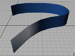
Surface extruded from a curve
To create an extrude surface:
In a NURBS object that contains at least one curve, turn on Extrude.
Move the cursor over the curve to extrude, and drag to set the initial amount.
By default, the surface extrudes along the NURBS model's local Z axis. A black gizmo indicates the direction of extrusion transforming the extrude surface's gizmo changes the direction of the extrude, letting you extrude along an axis that isn't aligned with a local coordinate axis.
3. Adjust the extrusion parameters.
When you turn on the Extrude button, or while an extrude sub-object is selected, a rollout with the extrusion parameters appears.
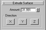
Amount: The distance the surface is extruded from the parent curve, in current 3DS MAX units.
Direction: Click X, Y, or Z to choose the axis of extrusion. Default = Z.
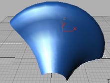
A lathe surface is generated from a curve sub-object. It is similar to a surface created with the Lathe modifier.
Surface created by lathing a curve
To create a lathe surface:
In a NURBS object that contains at least one curve, turn on Lathe.
Click the curve to lathe.
The lathe surface rotates about the NURBS model's local Y axis. The initial lathe amount is 360 degrees. A black gizmo indicates the axis of the lathe transforming the lathe surface's gizmo changes the shape of the lathe, and lets you lathe around an axis that isn't aligned with a local coordinate axis.
3. Adjust the lathe parameters.
When you turn on the Lathe button, or while a lathe sub-object is selected, a rollout with the lathe parameters appears.
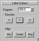
Degrees: Sets the angle of rotation. At 360 degrees (the default), the surface completely surrounds the axis. At lower values, the surface is a partial rotation.
A partial lathe (degrees = 135)
Direction: Click X, Y, or Z to choose the axis of rotation. Default = Y.
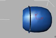

X, Y, and Z rotations of the same curve
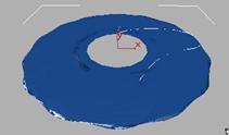
Align: Positions the axis of rotation relative to the curve. Click Min (the default) to locate the lathe axis at the curve's negative local X-axis boundary. Click Center to locate the lathe axis at the curve's center. Click Max to locate the lathe axis at the curve's positive local X-axis boundary.
Min, Center, and Max lathes of the same curve (Y-axis)
A ruled surface is generated from two curve sub-objects. It lets you use curves to design the two opposite borders of a surface.
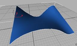
Using two curves to create a ruled surface
To create a ruled surface:
In a NURBS object that contains at least two curves, turn on Ruled.
Drag from one curve to the other.
3DS MAX generates a dependent surface using the two curves as the surface's opposite edges. It generates the perpendicular edges automatically.
You can animate the parent curves or their CVs to change the ruled surface.
When you turn on the Ruled button, and while a ruled surface sub-object is selected, a rollout with the ruled surface parameters appears at the bottom of the command panel.
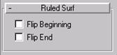
Flip Beginning and Flip End: Flip one of the curve directions used to construct the ruled surface. A ruled surface is created using the directions of the parent curves. If the two parents have opposing directions, this can lead to a ruled surface shaped like a bow tie. To correct the situation, use Flip Beginning or Flip End to have the ruled surface constructed using a direction opposite the corresponding parent curve's direction. These controls spare you the need to actually reverse the curve.
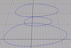
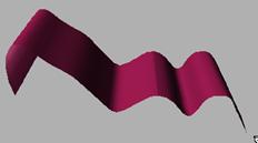
A U Loft surface interpolates a surface across multiple curve sub-objects. The curves become U-axis contours of the surface.
|
|
|
|
Using multiple curves to create a U Loft surface
Tip: U Lofts can be extremely dense surfaces. To improve performance while working with viewports, set the surface approximation for viewports to Curvature Dependent. See "Surface Approximation," below.
To create a U Loft surface:
In a NURBS object that contains at least two curves, turn on U Loft.
Click the first curve.
Click additional curves in succession.
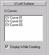
3DS MAX creates the U Loft, "stretching" it across the curves you click. The order in which you click the curves can affect the shape of the U Loft surface. The names of the curves appear in the U Loft Surface creation rollout. You can turn off Display While Creating to prevent display of the surface until you're done. This can speed up creation time.
While creating a U Loft, you can press BACKSPACE to remove the last curve you clicked from the list of U Loft curves.
Right-click to end U Loft creation.
When you turn on the U Loft button, or while a U Loft sub-object is selected, a rollout with the U Loft parameters appears. This rollout appears only during U Loft creation, and when one U Loft sub-object is selected. It isn't possible to edit more than one U Loft at a time, so unlike other NURBS sub-objects, the rollout doesn't appear when multiple U Loft sub-objects are selected.
Tip: When you edit a U Loft sub-object, close the Surface Common rollout to see the U Loft Surface rollout more readily.
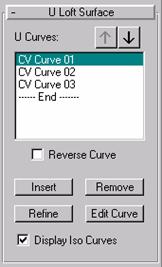
U Curves: This list shows the name of the curves you click, in the order you click them. You can select curves by clicking their names in this list. Viewports display the selected curve in blue. Initially the first curve is the one selected.
Arrow Buttons: Use these to change the order of curves used to construct the U Loft. Select a curve in the list, and then use the arrows to move the selection up or down.
Reverse Curve: When set, reverses the direction of the selected curve.
Insert: Adds a curve to the U Loft surface. Click to turn on Insert, then click the curve. The curve is inserted before the selected curve. To insert a curve at the end, first highlight the "----End-----" marker in the list.
Remove: Removes a curve from the U Loft surface. Select the curve in the list, and then click Remove.
Refine: Refines the U Loft surface. Click to turn on Refine, then click a U-axis iso curve on the surface. (As you drag the mouse over the surface, the available curves are highlighted.) The curve you click is converted to a CV curve and inserted into the loft and the U Curves list. As when you refine a point curve, refining a U Loft can change the curvature of the surface slightly. Once you've refined the surface by adding a U curve, you can use Edit Curve to change the curve.
Edit Curve: Lets you edit the currently selected curve without switching to another sub-object level. Click to turn on Edit Curve. The points or CVs of the curve are displayed, as well as the control lattice if the curve is a CV curve. You can now transform or otherwise change the points or CVs as if you were at the Point or Curve CV sub-object level. To finish editing the curve, click to turn off Edit Curve.
Tip: When you edit curves in a U Loft, turning off display of the U Loft itself can make the curves easier to see and improve performance as well. Use CTRL + D (while the Plug-In Keyboard Shortcut Toggle is on) to toggle display of dependent sub-objects, including U Lofts.
[At present the U Loft surface can deviate from the curve if you edit a curve in a U Loft by increasing the weight of the curve CVs. You can work around this by refining the curve at the point where the surface deviates.]
Display Iso Curves: When set, 3DS MAX displays the U Loft's V-axis iso curves as well as the U-axis curves used to construct the loft.
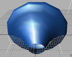
Creates a surface that caps a closed curve or the edge of a closed surface. Caps are especially useful with extruded surfaces.
Capping an extrude surface
To create a cap surface:
In a NURBS object, turn on Cap.
Move the mouse over the closed edge or the closed edge of a closed surface.
If 3DS MAX can create the cap, the curve or edge is highlighted in blue.
Click the highlighted curve or edge.
Cap surfaces have no parameters rollout.
To create independent surfaces out of top-level NURBS curve objects, use the Extrude and Lathe modifiers. Extrude adds height to the curve, creating a shape by sweeping it along the curve's local Z-axis. Lathe creates a surface of rotation, revolving the shape along a specified axis.
The Extrude and Lathe modifiers treat NURBS curves the same way they treat shapes. The advantage of using NURBS curves instead of shapes is in the different possible shapes that NURBS geometry and editing provide.
Tip: When you create a complicated surface, especially with the Lathe modifier, you often want to render both sides of the surface. Turn on Force 2-Sided in the Render Scene dialog to see both sides of the extruded or lathed surface. To see both sides in viewports, turn on Force 2-Sided in the Viewport Configuration dialog.
By default, an object with Extrude or Lathe collapses to an Editable Mesh object. To have Extrude or Lathe output collapse to a NURBS object, change the setting to NURBS in the Output area of the Extrude or Lathe rollout, and then collapse the modifier stack.
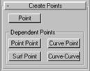
In addition to the points that are an integral part of Point Curve and Point Surface objects, you can create "free-standing" points. Such points can help you construct Point Curves by using the Curve Fit button in one of the Create Curves rollouts. (See the earlier section, "Creating Dependent Curves.") You also use dependent points to trim curves.
You create individual points as NURBS sub-objects, while you are modifying a NURBS curve or NURBS surface. To create points individually, you use the Create Points rollout.

These are the toolbox buttons for creating Point sub-objects:
|
|
Create an independent point.
|
|
Create a dependent point point.
|
|
Create a dependent curve point.
|
|
Create a dependent curve-curve intersection point.
|
|
Create a dependent surface point.
Creates an independent, free-standing point. Click to turn on this button, and then click in a viewport to position the point.
Independent point sub-objects have no additional parameters.
Creates a dependent point that lies at a point or relative to it.
To create a dependent point point:
Turn on Point Point, click in a viewport to position the point, and then adjust the point's position relative to the original point by adjusting the Point Point parameters.
When you turn on the Point Point button, or while a point point sub-object is selected, the Offset Point rollout appears.
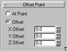
At Point: When chosen, the dependent point has the same location as the original, parent point.
Offset: When chosen, moves the point according to the X,Y,Z values, which are relative to the parent point.
Creates a dependent point that lies on a curve or relative to it.
To create a dependent curve point:
Turn on Curve Point, click a curve to position the point, and then adjust the point's position relative to the curve by adjusting the Curve Point parameters.
When you turn on the Curve Point button, or while a curve point sub-object is selected, the Curve Point rollout appears.
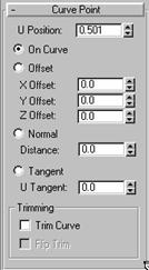
The point can either be on the curve or off the curve. If it is on the curve, the U Position is the only control of its location. The U Position specifies a location along the curve (based on the curve's local U axis). There are three ways to displace the point's location relative to the U position:
Offset moves the point according to a relative X,Y,Z location.
Normal moves the point along the direction of the curve's normal. (Negative values move it opposite to the normal.)
U Position
Tangent moves the point along the tangent of the U Position.

Offset Normal Tangent
Offset, normal, and tangent displacement of a curve point
Trimming
This area lets you trim the parent curve.
Trim Curve: When on, trims the parent curve against the curve point's U position. When off (the default), the parent isn't trimmed.
Flip Trim: When on, trims in the opposite direction.
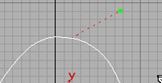
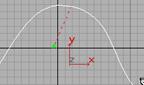
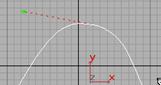
Creates a dependent point that lies on a surface or relative to it. (This is available only in Surface objects, not Curves.)
To create a dependent surf point:
Turn on Surf Point, click a surface to position the point, and then adjust the point's position relative to the surface by adjusting the Surface Point parameters.
When you turn on the Surf Point button, or while a surface point sub-object is selected, the Surface Point rollout appears. These controls are similar to the Curve Point controls.
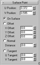
The point can either be on the surface or off the surface. If it is on the curve, the U Position and V Position control its location. This is a location on the surface, based on the surface's local UV coordinates). There are three ways to displace the point's location relative to its UV position:
Offset moves the point according to a relative X,Y,Z location.
Normal moves the point along the direction of the curve's normal. (Negative values move it opposite to the normal.)
Tangent moves the point along the tangent of the UV position.
Creates a dependent point at the intersection of two curves.
To create a dependent curve-curve point:
Turn on Curve-Curve, then drag from the first curve to the second.
3DS MAX creates the point at the nearest intersection between the two curves. You can use the curve-curve parameters to trim the parent curves.
When you turn on the Curve-Curve button, or while a curve-curve point sub-object is selected, the Curve-Curve Intersection rollout appears.
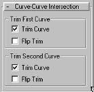
Trim First Curve and Trim Second Curve
These two areas let you control how the parent curves are trimmed. The controls are the same in each. "First" and "second" refer to the order in which you picked the parent curves.
Trim Curve: When on, trims the parent curve against the curve-curve point. When off (the default), the parent isn't trimmed.
Flip Trim: When on, trims in the opposite direction.
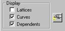
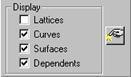
The check boxes in the General rollout for a NURBS curve or surface control how the object is displayed in viewports. If all check boxes are turned off, the NURBS object is invisible (except, when selected, for its white bounding-box indicators in shaded viewports).
Lattice: When turned on, displays control lattices, in dashed yellow lines. (You can change the lattice color by using the Colors panel of File/Preferences.) The Curve CV and Surface CV sub-object levels also have a local Display Lattice toggle, which overrides this global setting at the sub-object level. The Curve CV and Surface CV settings are independent in other words, at the sub-object level you can turn on the lattice for an object's curves but not its surfaces, or vice versa.
Keyboard shortcut (while Plug-In Keyboard Shortcut Toggle is turned on): CTRL + H
At the object level, this shortcut is equivalent to turning Lattice on or off. At the sub-object level, CTRL + H overrides the setting of Lattice, toggling the local Display Lattice setting.
Curves: When turned on, displays curves.
Surfaces: When turned on, displays surfaces as a wireframe meshes in wireframe viewports or as rendered surfaces in shaded viewports.
Dependents: When turned on, displays dependent sub-objects.
Keyboard shortcut (while Plug-In Keyboard Shortcut Toggle is turned on): CTRL + D
![]() NURBS Creation Floater: Turn on to display the
NURBS sub-object creation toolbox. See
the previous section, "Using the NURBS Toolbox to Create Sub-Objects."
NURBS Creation Floater: Turn on to display the
NURBS sub-object creation toolbox. See
the previous section, "Using the NURBS Toolbox to Create Sub-Objects."
Keyboard shortcut (while Plug-In Keyboard Shortcut Toggle is turned on): CTRL + T
Although NURBS curves and surfaces are analytically generated, to generating and displaying them requires curves to be approximated by line segments, and surfaces by faces. You use the controls described in this section to set approximation parameters, and the kind of approximation used.
Curve approximation controls appear in the creation parameters for curve objects, and in a Curve Approximation rollout for NURBS models (top-level NURBS surface objects). At the model level, the approximation controls affect all curve sub-objects in the model.
Curve approximation is done by segments. A segment of a curve is the portion of the curve between one point or CV point and the next. (For a CV, which doesn't lie on the curve, the segment is determined by the CV's parametric knot. The transition from one CV curve segment to another isn't visible in viewports.) One or more line segments, or steps, are used to approximate each segment of the curve.
Curve approximation parameters aren't animatable.
Steps: The maximum number of line segments used to approximate each curve segment. If 3DS MAX displays or renders the curve with angles, increase this value. This control is disabled unless you turn off Adaptive. The Steps value can range from 1 to 100.
Optimize: Turn on this check box to optimize the curve. When on, interpolation uses the specified Steps value unless two segments are collinear, in which case they are converted to a single segment.
Adaptive: (The default.) Segments the curve adaptively, based on its curvature. In other words, 3DS MAX assigns the curve more segments points or CVs where its curvature is greatest, fewer points or CVs where its curvature is less.
The Surface Approximation rollout controls how surface sub-objects in the NURBS model are approximated for the purposes of rendering and viewport display. It is important to know that NURBS can be approximated differently in viewports and in the renderer. Typically you will want to set viewport display to be clear and quick, while you will want rendered display to be smooth, accurate, and "realistic." However, the approximation you choose for viewports creates a mesh, and the kind of mesh you choose can affect the behavior of modifiers that you later apply to the NURBS model.
The first two controls in this rollout are radio buttons so you can select which kind of display output, viewport or renderer, these parameters control.
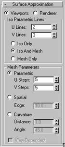
Surface approximation parameters aren't animatable.
Viewports: When chosen, the rollout affects how surfaces in the NURBS object are displayed interactively in viewports, including shaded viewports, and by the preview renderer.
The Viewports surface settings are also used when you apply a mesh modifier such as Mesh Select to the NURBS object. This is important because it can affect the scene's geometry.
Renderer: When chosen, the rollout affects how surfaces in the NURBS object are displayed by the renderer, and by the draft renderer for Quick Render.
Iso Parametric Lines
The controls in this area affect the display of the NURBS surface in viewports. They are disabled while Renderer is chosen.
U Lines and V Lines: The number of lines used to approximate the NURBS surface in viewports, along the surface's local U and V dimensions, respectively. Reducing these values can speed up the display of the surface, but reduce accuracy of the display. Increasing these values increases accuracy at the expense of time. Setting one of these values to 0 displays only the edge of the object in the corresponding dimension.
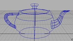
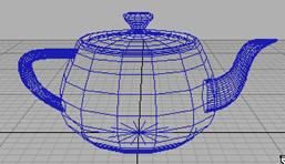
Iso and mesh displays of a NURBS teapot
Iso Only: When chosen, all viewports display iso line representations of the surface. Iso(parametric) lines are similar to contour lines. The lines show where the NURBS surface has a constant U value or V value or both. Iso line representations can be less crowded and easier to visualize than wire mesh representations.
Iso and Mesh: (The default.) When chosen, wireframe viewports display iso line representations of the surface, and shaded viewports display the shaded surface.
Mesh Only: When chosen, wireframe viewports display the surface as a wire mesh, and shaded viewports display the shaded surface. In wireframe viewports, this option lets you see the curve approximation used for viewports.
Mesh Parameters
The controls in this area affect the display of the NURBS surface in either viewports, if Viewports is chosen, or by the renderer, if Renderer is chosen. You can choose between three algorithms. Each approximates NURBS surfaces by tessellating them in a different way.
Note: When Viewports is chosen, you must also choose Mesh Only in order to see the effect of the Mesh Parameter settings in wireframe viewports.
Tip for Viewports: Use Parametric or Curvature for quick display. The algorithm creates the mesh, so if you modify the NURBS object with Mesh Select, choose the algorithm that gives the result you need. If you use modifiers heavily, Spatial or Parametric are usually better than curvature, because of their regular tessellation. Curvature-dependent tesselation can cause problems with some 3DS MAX modifiers.
Tip for the Renderer: Use either Spatial or Curvature to obtain the most accurate rendering. Curvature can be the more efficient choice for rendering animated surfaces.
Parametric: Generates a fixed tessellation based on U Steps by V Steps. Increasing these parameters increases accuracy at a cost of speed, and vice versa, but in general this is the quickest and least accurate way to approximate a NURBS surface.
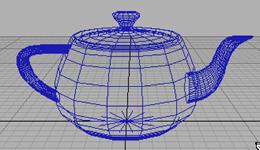
Parametric mesh of the NURBS teapot
Spatial: Generates a uniform tessellation made of triangular faces.
The Edge parameter specifies the maximum length of a triangular face in the tesselation, in current 3DS MAX units. Decreasing this value increases accuracy but increases rendering time.
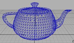
Spatial mesh of the NURBS teapot
Curvature: (The default.) Generates a variable tessellation based on the curvature of the surface. The tessellation has a finer grain where the surface is more curved. Changing surface curvature dynamically changes the curvature tessellation.
The Distance parameter specifies how far the approximation can deviate from the actual NURBS surface. Distance is a percentage of the diagonal of each surface's bounding box. Each surface in an object is tessellated based on its size, independently of other surfaces, and scaling a surface doesn't change its tessellation. Decreasing this value increases accuracy but increases rendering time. When you set Distance to 0.0, 3DS MAX ignores this parameter and uses the Angle to control accuracy.
The Angle parameter specifies the maximum angle between faces in the approximation. Decreasing this value increases accuracy but increases rendering time. When you set Angle to 0.0, 3DS MAX ignores this parameter and uses the Distance to control accuracy.
When both Distance and Angle are 0.0, the surfaces degenerate and can become flat surfaces.

Curvature mesh of the NURBS teapot
View-Dependent (for the Renderer only): When turned on, takes the object's distance from the camera into account while calculating its tessellation. This can improve rendering time by not generating fine-grained tesselations for objects that are in the distance of the rendered scene. This control is disabled while Viewports is active.
Many controls are common to the various kinds of sub-objects in NURBS models (with the exception of Imports, as previously described). This section describes these common controls.
One way to alter a NURBS model is to transform its sub-objects. This lets you interactively change the model's curvature and shape. Transforming points or CVs is especially useful for adjusting the shape of a NURBS curve or surface.
To transform sub-objects:
Select the NURBS object.
![]() Go to the Modify command panel.
Go to the Modify command panel.
In the Modifier Stack rollout, turn on Sub-Object, then choose the sub-object level you want.
If you choose Point as the sub-object level, points become visible in viewports. If you choose Curve CV or Surface CV, both the CVs for curves or surfaces and their control lattices become visible.
4. Select one or more sub-objects.
The sub-object selection tools are the same as for other kinds of 3DS MAX sub-objects. This includes using the "H" key in conjunction with the status bar's Plug-In Keyboard Shortcut Toggle, as previously described in "Sub-Object Selection."
See the next section, "Selection Controls," for more detail about the selection controls provided in the Modify command panel for different kinds of NURBS sub-objects.
If you choose Imports, then when you select an imported object it is highlighted in shaded viewports as well as wireframe viewports.
5. ![]() Turn on Move or another transform and then
drag in a viewport to transform the selection.
Turn on Move or another transform and then
drag in a viewport to transform the selection.
The shape of the model changes as you interactively transform the sub-objects.
Tips:
![]() The Lock Selection Set button is useful when
you transform NURBS sub-objects. You can make a selection in one viewport,
click Lock Selection Set (or press the SPACE BAR), then transform the selection
in a different viewport.
The Lock Selection Set button is useful when
you transform NURBS sub-objects. You can make a selection in one viewport,
click Lock Selection Set (or press the SPACE BAR), then transform the selection
in a different viewport.
When you move point and CV sub-objects, move them as systematically as possible to avoid "getting lost."
Avoid moving points or CVs so they cross over or under adjacent points. This can create odd-looking warps or overlaps in the surface.
There is a Selection area of the rollout for all NURBS sub-objects except Imports. These buttons let you control just which sub-objects to select. They differ depending on the kind of sub-object, and they are described in the sections that follow.
Note: There is no delete modifier for NURBS curves, as there is for splines. There are two NURBS selection modifiers, NCurve Sel and NSurf Sel, described below under "NURBS and Modifiers."
Name
The Name field shows the name of the currently selected sub-object. It is blank if multiple sub-objects are selected.
By default, the name is the name of the sub-object type ("CV," "Point," "CV Curve," "Point Curve," "CV Surf,"or "Point Surf") followed by a sequence number. You can use this field to give the sub-object a name that you choose.
Import sub-objects have a Name field, but no other selection controls.
Point and CV Selection Buttons
The selection controls for point and CV sub-objects are the same except for their tool-tip labels.
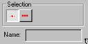
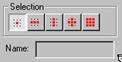
For curve points and CVs For surface points and CVs
Point and CV sub-object selection controls
For Curve CVs, you can choose to select either individual CVs (or groups, by dragging), or all the CVs in the curve at once.
For CV Surfaces, the selection buttons are as follows:
Single CVs: (The default.) When on, you can select individual CVs by clicking, or groups of CVs by dragging a region.
Row of CVs: When on, clicking a CV selects the entire row the CV belongs to. Dragging selects all rows in the region.
Column of CVs: When on, clicking a CV selects the entire column the CV belongs to. Dragging selects all columns in the region.
Row and Column of CVs: When on, clicking a CV selects both the row and column the CV belongs to. Dragging selects all rows and columns in the region.
All CVs: When on, clicking or dragging selects all the CVs in the surface.
Remember that when all CVs are selected, adjusting the rational Weight value has no effect.
Note: Rows and columns are easily visible when the NURBS surface is planar, or nearly so. When the surface has a complicated curvature, rows and columns can be harder to see. The Row, Column, and Row/Column buttons can be especially useful in this situation.
Curve Selection Buttons
The selection buttons for Curve sub-objects let you select either individual curves, or curves that are connected in space.
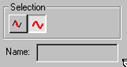
Curve sub-object selection controls
Single Curve: Clicking or transforming a curve selects only a single independent curve sub-object.
All Connected Curves: Clicking or transforming a curve selects all curve sub-objects that are connected within the NURBS object. To be connected, two curves must have fused points, or one curve must be a connected dependent (a blend, fillet, or chamfer) of the other.
Surface Selection Buttons
The selection buttons for Surface sub-objects let you select either individual surfaces, or surfaces that are connected in space.
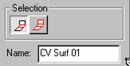
Surface sub-object selection controls
Single Surface: Selecting a surface selects only that surface sub-object.
All Connected Surfaces: Selecting a surface selects all surface sub-objects that are connected within the NURBS surface object. To be connected, two surfaces must have fused points, or one surface must be a connected dependent (a blend) of the other.
Using the Keyboard to Select Sub-Objects
With the CTRL key and the arrow keys, you can select sub-objects by using the keyboard. The arrows traverse the sub-objects. To do so, follow these steps:
![]() Turn on the Plug-In Keyboard Shortcut
Toggle.
Turn on the Plug-In Keyboard Shortcut
Toggle.
![]() At the sub-object level, set the selection
controls to select a single sub-object.
At the sub-object level, set the selection
controls to select a single sub-object.
Click to select one sub-object.
Hold down CTRL and use the arrow keys to move among the sub-objects at the current level.
At the Curve and Surface sub-object levels, the left and right arrow keys move forward and backward through individual sub-objects in the order they were created. The up and down arrows are simply equivalent to left and right.
For curves at the Point and CV Curve levels, the arrow keys traverse points or CVs along the length of the curve you selected in step 3. The arrow keys don't move between curve sub-objects.
For surfaces at the Point and CV Surface levels, the left and right arrow keys traverse the U dimension of a surface, while the up and down arrow keys traverse the V dimension of the surface. The arrow keys don't move between surface sub-objects they traverse only the surface you selected in step 3.
The arrow keys don't traverse individually created points that aren't part of a curve or surface.
You can hide or unhide NURBS sub-objects as you do 3DS MAX objects. Hidden sub-objects are invisible in viewports. They remain renderable (at the sub-object level, hiding doesn't affect the renderer). You can't select hidden sub-objects.
Hide: Click to hide the current sub-object selection.
Unhide All: Click to unhide all hidden sub-objects at the current sub-object level.
You can make a dependent point, curve, or surface sub-object independent.
Caution: When you make an object independent, you lose the animation controllers for all objects that depend on it in turn. When you make point objects independent, you lose the animation controllers for all points on the curve or surface.
To make a dependent sub-object independent:
Select the dependent object, and then click Make Independent.
The sub-object no longer depends on its parent objects, and editing them has no effect on the newly independent sub-object, which retains its shape unless you edit it explicitly.
You can't make CV sub-objects independent. CVs are always part of a curve or surface.
You can also use Make Independent to convert a point curve or point surface into a CV curve or CV surface. The original points are deleted from the scene in this respect, using Make Independent on a point curve or surface differs from using it on other kinds of dependent sub-objects.
You can create a new curve or surface object by detaching a curve or surface sub-object from a NURBS model. To do so, select the curve or surface and then click Detach. 3DS MAX displays a dialog to let you enter a name for the new NURBS object (the default name is "Curve" or "Surface" followed by a sequence number). The new object is no longer part of the original NURBS object.
You can also use the Detach button to create a new NURBS object that is a copy of a curve or surface sub-object. To do so, select the curve or surface, and click to turn on Copy before you click Detach. 3DS MAX displays a dialog to let you enter a name for the new object. The original curve or surface sub-object remains part of the NURBS object you were editing, but the copied curve or surface is now a NURBS object of its own.
This section describes the controls for point and CV sub-objects. A rollout labeled CV or Point contains the CV or point sub-object controls for NURBS curve and surface objects.
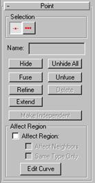
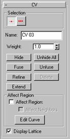
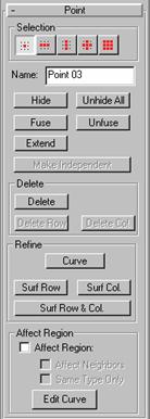
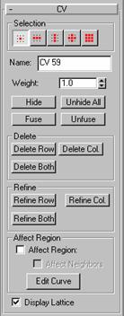
on a curve object on a surface object
CV and point sub-object rollouts
The selection controls and other common controls are described in the previous section, "Common Sub-Object Controls." As the illustration shows, there are differences between the controls for CVs and points. These differences are described as they arise in the sections that follow.
For CV Curves and Surfaces (but not Point Curves or Surfaces), you can adjust the rational weights of the sub-object selection. Use the Weight field and spinner to do this.
Each CV also has a weight, which you can use to adjust the CV's effect on the curve or surface. Increasing the weight pulls the surface towards the CV. Decreasing the weight relaxes the surface away from the CV.
By default, the weight is 1.0 for the CVs of NURBS objects you create in the Create command panel or the NURBS sub-object creation rollouts. The weight of CVs in 3DS MAX geometry that you convert to NURBS can vary, depending on the object's original shape.
You can change the Weight when multiple CVs are selected. Using the Weight field or spinner while multiple CVs are selected assigns all of them the value you choose. Because weights are relative, using the Weight control when all CVs are selected has no visible effect.
Tip: To create an indentation in a surface, sometimes it is easier to increase the weight of the CVs surrounding the indented area, rather than trying to move the indented area's CVs.
You can add points or CVs to a curve or surface, or remove them. (You can also add or remove points or CVs, and otherwise edit a NURBS surface, by using the surface sub-object rollout, as described below in "Surface Editing.")
Caution: When you add points (with Refine or Extend) or delete points or CVs, you lose the animation controllers for all points or CVs on the curve or surface.
To remove points or CVs from a curve:
Select a point or CV.
Click Delete.
Keyboard shortcut: DEL
3DS MAX deletes the point or CV, and updates the shape of the curve.
The controls for deleting points or CVs differ slightly between Point Surfaces and CV Surfaces.
Note: A point curve must have at least two endpoints. A CV curve must have at least one more CV than the degree of the curve. (See the glossary or "CV Curve Degrees," below.)
To remove points from a surface:
Select a point, row, or column.
The appropriate Delete buttons are enabled.
Click Delete, Delete Row, or Delete Col.
3DS MAX deletes the point, row, or column.
To remove CVs from a surface:
Select a row, column, or a row and column.
The appropriate Delete buttons are enabled.
Click Delete Row, Delete Col., or Delete Both.
3DS MAX deletes the row, column, or both.
To add a point or CV to a curve:
Turn on Refine.
Click the curve where you want to add the point or CV.
3DS MAX adds a point or CV at the location you clicked.
For surfaces, the controls for adding points differ between CV Surfaces and Point Surfaces.
To add CVs to a CV Surface:
Click Refine Row, Refine Col., or Refine Both.
Click the surface.
3DS MAX adds a row, column, or both close to the point where you clicked the surface. The new CVs are placed so they preserve the curvature of the surface.
To add points to a Point Surface:
In the Refine area, click Surf Row, Surf Col., or Surf Row & Col.
Click the surface.
3DS MAX adds a row, column, or both close to the point where you clicked the surface. The new points are placed on the surface so they preserve the surface's curvature.
If a Point Curve sub-object is present in the NURBS object, you can use the Curve button to add points to it as well as to the surface.
You can connect a point to a point or a CV to a CV. (You can't fuse a CV to a point, or vice versa.) This is one way to connect two curves or surfaces. It is also a way to change the shape of curves and surface.
Fusing points does not combine the two point sub-objects. They are connected but remain distinct sub-objects that you can unfuse at a later time.
Fused points behave as a single point until you unfuse them. Fused CVs behave much like a single point, but the property of multiplicity for coincident CVs also applies. (See "NURBS Concepts" and "Creating NURBS Curves," above.) The fused CVs have proportionally more influence on the curve, which can become more sharply curved in the fused CVs' vicinity, or even angular if more than two CVs are fused together.
To fuse two points or CVs:
Turn on Fuse.
Click on a point or CV without releasing the mouse. Drag to another point or CV, and then release the mouse.
The point or CV you choose first acquires the position of the second point or CV, and becomes dependent to it. If the first point or CV had an animation controller, the controller is discarded. If the second point or CV has an animation controller, the first point or CV acquires it, too.
To unfuse fused points or CVs:
Select the fused point or CV.
Click Unfuse.
Now you can move and otherwise edit the two points or CVs independently.
The Affect Region controls for NURBS curves and surfaces are like the Affect Region controls for 3DS MAX Editable Mesh objects. Affect Region controls make a point or CV behave as if surrounded by a "magnetic field." Unselected points or CVs within the field are drawn along smoothly while you move the selected one.
With this feature, you can sculpt the points or CVs of a curve or surface-for example, drawing a sphere into an egg, or gently curving a flat surface into hills and valleys.
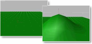
Using Affect Region
The Affect Region area of the CV or Point rollout contains the controls for this feature. The Affect Region check box is turned off by default.
Before you begin, you might need to increase the number of CVs or points on the surface. This allows smoother and more complex reshaping effects. See the earlier section on "Adding and Deleting Points and CVs."
A single point or CV works well for many purposes. Moving a point or CV along a single axis is the most useful for smoothly raising and lowering surfaces. For multiple points or CVs, you can also use Rotate or Scale.
To transform a region:
Using sub-object selection, select one or more points or CVs for the center of transformation.
Turn on Affect Region.
Transform the point or CV.
A region around the selected point or CV is transformed accordingly.
Move is the most common transform. Rotate and Scale can be used with a non-local transform center.
Tip: If Affect Region appears not to be working, the Falloff value might be too small for the size of your surface. Click Edit Curve, and in the Edit Affect Region Curve dialog (described below), increase the value of Falloff so it encompasses other points or CVs.
These are the Affect Region controls:
Affect Region: Turn on this check box to make point or CV transforms affect a region of the curve or surface.
Affect Neighbors: Turn on this check box to have the transform affect not only points or CVs on this curve or surface but on all curves and surfaces in the NURBS object that are within the Falloff region.
Same Type Only (only for Point Curves and Surfaces): Turn on this check box to have the transform affect only neighboring points of the same type that is, either constrained points or unconstrained points.
Edit Curve: Click to edit the curve 3DS MAX uses in affecting the region. See the next subsection for a description of the Edit Affect Region Curve dialog.
Editing the Curve
Edit Curve lets you redefine the affected region for subsequent operations. Editing the curve does not change any existing region, only the next one you create. You can experiment with a curve setting, undo it, and try another setting with the same selection.
When you click Edit Curve, the following dialog appears.

The Edit Affect Region Curve dialog has these controls to reshape the Affect Region curve:
Falloff: Distance in current units from the
center to the edge of a sphere defining the affected region. Use higher falloff
settings to achieve more gradual slopes, depending on the scale of your
geometry.
Default = 20.
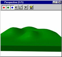
Example of Falloff
Pinch: Raises and lowers the top point of the curve along the vertical axis. Sets the relative "pointedness" of the region. When negative, a crater is produced instead of a point. At a setting of 0, Pinch produces a smooth transition across this axis. Default = 0.
Bubble: Expands and contracts the curve along the vertical axis. Sets the relative "fullness" of the region. Limited by Pinch, which sets a fixed starting point for Bubble. A setting of 0 for Pinch and 1.0 for Bubble produces a maximum smooth bulge. Negative values for Bubble move the bottom of the curve below the surface, creating a "valley" around the base of the region. Default = 0.
[TWO ILLUSTRATIONS TO IMPORT OR CREATE HERE]
Examples of Pinch and Bubble
This section describes the controls that are common to Point and CV curves. A rollout labeled Curve Common contains the curve sub-object controls for NURBS models.
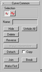
Curve sub-object rollout
The selection controls and other common controls are described in the previous section, "Common Sub-Object Controls."
You can delete curve sub-objects.
To delete a curve:
Select the curve and then click Delete.
Keyboard shortcut: DEL
For a closed curve, lets you choose a position that becomes the first vertex of the curve.
The first point or CV is significant when you use the NURBS curve like a spline as a Loft path or shape, as a Path Controller path, or as a motion trajectory. For these purposes, the first vertex of the curve is significant. If the curve is a closed curve, you can use Make First to set the curve's first vertex.
To select a first vertex on the curve:
Turn on Make First, and then click a location on the curve.
If the curve is closed, the location you click becomes the new first vertex, and the curve's points or CVs adapt to maintain the curvature.
If the curve is open, clicking it has no effect.
Caution: Using Make First discards any animation controllers for the points or CVs in the curve.
If the curve is open, the first vertex must be one of the endpoints (by default, it is the first you created). The Make First button has no effect, but you can use Reverse to change the curve's direction.
Reverses the order of the CVs or points in a curve, so that the first vertex becomes the last, and the last becomes the first. (See the previous section, "Make First.")
To reverse a curve:
Select a curve sub-object, and then click Reverse.
Joins two curve sub-objects together.
Caution: When you join two curve sub-objects, you lose the animation controllers for all point or CVs on both curves.
To join two curves:
In a NURBS object that contains two curve sub-objects, turn on Join.
If the gap between the curves is small less than about 30 units set the Tolerance value to a value greater than the distance of the gap.
Click one curve near the end that you want to connect. Drag to near the end of the other curve, and then release the mouse.
The endpoints of the two curve objects are connected by new segments, and the two original curves are replaced by a single curve. (Unlike a Blend curve, the new segment is part of the curve object, not a dependent sub-object.)
Tolerance: A distance in 3DS MAX units. If the gap between the curves you are joining is greater than this value, 3DS MAX creates the join by first creating a blend curve and then joining the three parts. If the gap is less than this value, or if the curves are overlapping or coincident, 3DS MAX doesn't create the blend.
Creating a blend and then joining the three curves into a single curve is the better technique. The result matches the parent curves well. Without the blend step, the resulting curve can deviate from the parent curves, in order to maintain smoothness. (The amount of deviation depends on how far from tangent the two input curves were at the join.)
A problem arises when there is a gap but it is too small. In this case, 3DS MAX generates the blend but because there isn't enough room for it, the resulting curve has a loop in it. To avoid this loop, set the Tolerance higher than the gap distance.
If you set the tolerance to 0.0, 3DS MAX chooses a value to use for the Tolerance.
Breaks a single curve into two curves.
To break a curve:
Turn on Break, and then click a curve.
The curve is split into two independent curve sub-objects. Two coincident (but independent) points or CVs are created at the location you clicked each is the endpoint of one part of the original curve.
If the curve is a closed curve, Break creates a single curve object, with its new start and end points at the location you clicked. The new start and end points are coincident but independent.
While a CV curve sub-object is selected, the CV Curve rollout appears.
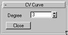
The higher the Degree value, the greater the continuity. The lower the degree, the more discontinuous the curve segments become. The degree can't be less than one or greater than the number allowed by the number of CVs in the curve. Degree 3 curves are adequate to represent continuous curves, and are stable and well behaved. Setting the degree greater than 3 isn't recommended. 3DS MAX supports higher-degree curves primarily to be compatible with models created using other surface modelers. Default = 3.
The number of CVs in a CV curve must be at least one greater than the curve's degree.
The CV Curve or Point Curve rollout, visible while an independent curve sub-object is selected, lets you make the curve a closed curve.
To close a curve:
Select the curve.
Click Close.
3DS MAX closes the curve by adding a segment between the curve's endpoints. The curvature of the new segment blends the curvature of the previous end segments.
Closing a curve does not add points or CVs to the curve. The curve retains its original number of points or CVs, and increases its number of segments by one.
This section describes the controls that are common to Point and CV surfaces. A rollout labeled Surface Common contains the surface sub-object controls for NURBS surfaces.
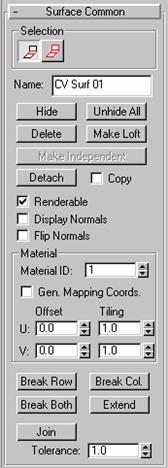
Surface sub-object rollout
The selection controls and other common controls are described in the previous section, "Common Sub-Object Controls."
You can delete surface sub-objects.
To delete a surface:
Select the surface and then click Delete.
Keyboard shortcut: DEL
Converts the surface sub-object to a (dependent) U Loft surface. Can also change the dimension used to construct a U Loft surface.
To make a surface a loft:
Select the surface sub-object.
Click Make Loft. This displays a Make Loft dialog.
Use the Make Loft dialog controls to choose the settings for the new surface, and then click OK.
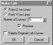
From U Iso Lines: Use curves along the surface's U dimension to construct the loft.
From V Iso Lines: Use curves along the surface's V dimension to construct the loft. If the surface was a U Loft to begin with, set this to change the lofting dimension.
Number of Curves: The number of curves used by the loft. Curves are distributed evenly along the appropriate dimension.
Preview: When set, displays a preview of the new loft surface. Clearing this toggle can speed up loft creation.
Delete Original Loft Curves: This is enabled only if the surface was a U Loft to begin with. If set, Make Loft deletes the original loft curves when you click OK. If cleared, the original curves remain where they are. Default = cleared.
These are the controls that affect how the surface sub-object appears when you render it with the renderer. They don't affect how the surface appears in shaded viewports.
Renderable: When turned on, the surface renders. Turn off to make the surface invisible in renderings. Default = On.
Display Normals: When turned on, 3DS MAX displays the normal for each surface selected There is one normal per surface sub-object. The normal is displayed at the surface's UV origin, so displaying normals can help you see how materials will be mapped. On the other hand, the normal can be hard to see if you are zoomed out.
Flip Normals: Turn on to reverse the direction of the surface normals.
Tip: The Flip Normals control is useful for viewing a surface that is mostly concave or mostly convex. With more complicated NURBS surfaces, you often want to render both sides of the surface. Turn on Force 2-Sided in the Render Scene dialog to see both sides of the surface. To see both sides of the surfaces in viewports, turn on Force 2-Sided in the Rendering Method panel of the Viewport Configuration dialog.
Material Controls
The controls in this area support materials, including tiling and positioning mapping coordinates on the surface.
Material ID: Use this to change the surface's material ID number. Multiple material IDs in a single NURBS object let you assign a Multi/Sub-Object material to the NURBS object.
Generate Mapping Coordinates: Generates mapping coordinates so you can apply mapped materials to the surface. Each surface in a NURBS object has its own set of mapping coordinates.
U and V Offset: Offsets mapping coordinates along the surface's local U axis or V axis. That is, at 0.0 (the default), the map begins at the U or V origin. Increasing an Offset value moves the map forwards along that axis, and decreasing it moves it backwards. These parameters are animatable.
U and V Tiling: Control the tiling of UV mapping coordinates that is, the number of time a mapped material's map is repeated in the surface's local U axis or V axis. Default = 1.0 for both axes (no tiling). These parameters are animatable.
The buttons Break Row, Break Col., or Break Both let you break a surface into two or four independent surfaces.
Break Row: Breaks the surface into two in the direction of a row (the surface's U axis).
Break Col.: Breaks the surface into two in the direction of a column (the surface's V axis).
Break Both: Breaks the surface into four in both directions.
To break a surface:
1. Turn on Break Row, Break Col., or Break Both, and then drag over the surface.
One or two blue curves appear on the surface to indicate where the break will occur.
2. When you have dragged to the location you want to break, click the surface.
Note: If you break a dependent surface the new, "broken" surfaces are all made independent.
Extends the surface by changing its length.
Caution: Extending a surface loses all animation controllers for the surface and its points or CVs.
To extend a surface:
Turn on Extend.
Move the mouse over the surface without depressing the mouse button. The edge that will be extended highlights in blue.
When the edge you want to extend is highlighted, press the mouse button, and then drag upward to increase the length of the surface, or downward to decrease the length.
Joins two surface sub-objects together. This operation is similar to creating a blend surface, but the new area becomes part of the surface object, not a dependent sub-object.
Caution: When you join two curve sub-objects, you lose the animation controllers for all point or CVs on both curves.
To join two surfaces:
In a NURBS object that contains two surface sub-objects, turn on Join.
If the gap between the surfaces is small less than about 30 units set the Tolerance value to a value greater than the distance of the gap.
Click one surface near the edge that you want to connect. The edge that will be connected is highlighted in blue. Drag to choose the edge you want to connect. Without releasing the mouse, drag to the other surface. The edge of the other surface is also highlighted in blue. Drag on the other surface to choose the edge to connect, and then release the mouse.
3DS MAX joins the two original surfaces, creating a single surface that replaces the two original surfaces. (Unlike a blend, the portion between the two original surfaces is part of the new surface, not a dependent surface sub-object.)
Tolerance: A distance in 3DS MAX units. If the gap between the surfaces you are joining is greater than this value, 3DS MAX creates the join by first creating a blend surface. If the gap is less than this value, or if the surfaces are overlapping or coincident, 3DS MAX doesn't create the blend.
Creating a blend and then joining the three surfaces into a single surface is the better technique. The result matches the parent surfaces well. Without the blend step, the resulting surface can deviate from the parent surfaces, in order to maintain smoothness. (The amount of deviation depends on how far from tangent the two input curves or surfaces were at the join.)
A problem arises when there is a gap but it is too small. In this case, 3DS MAX generates the blend but because there isn't enough room for it, the resulting surface has a loop in it. To avoid this loop, set the Tolerance higher than the gap distance.
If you set the tolerance to 0.0, 3DS MAX chooses a value to use for the Tolerance.
The close controls let you close a surface. They appear on the Point Surface or CV Surface rollout while an independent surface sub-object is selected. They have no effect if the surface is already closed in that direction.
Close Rows: Closes the surface by joining the ends of its rows.
Close Cols.: Closes the surface by joining the ends of its columns.
To close a surface:
Select the surface sub-object.
Click Close Rows or Close Cols.
Two modifiers, NCurve Sel and NSurf Sel, let you place a NURBS sub-object selection on the modifier stack. This lets you modify only the selected sub-objects. Also, selected curve sub-objects are Shape objects that you can use as paths and motion trajectories.
NSurf Sel can select any kind of NURBS sub-objects except imports. NCurve Sel selects only objects available to top-level curve objects. In other words, it can select any kind of NURBS sub-objects except surfaces and imports. Each sub-object selection is of one particular sub-object level only.
To use a NURBS select modifier:
With a NURBS object selected in the Modify command panel, apply either NCurve Sel or NSurf Sel.
The select modifiers have no controls at the object level.
Click to turn on Sub-Object in the Modifier Stack rollout, and choose a sub-object level from the drop-down list.
The select modifiers have the same selection controls you see for the corresponding sub-object type, except that selecting connected curves or surfaces is not available.
Use the selection controls to create a selection set of the chosen sub-object type.
With the NSurf Sel modifier, the selection can be of any NURBS sub-object level except imports. With NCurve Sel, the selection can be of any sub-object level except surfaces and imports.
Once you have used the modifier to create the selection, you can apply other modifiers to it. If the selected sub-object is a curve, you can also use it as a path or trajectory.
Note: The NURBS select modifiers don't support copy and paste of selections as Mesh Select does. Copying and pasting mesh selections is based on vertex indexes. NURBS selections are based on object IDs, which are unique to each model.
affine transformation A geometric transformation move, rotation, or scale that can alter distances between points or angles between lines, but preserves straight lines and the parallel relation between parallel lines. 3DS MAX Transform operations are affine transformations. NURBS are invariant under affine transformations.
Bézier curve A curve modeled using a parametric polynomial technique. Bézier curves were developed by P. Bézier for computer modeling in automobile design. They are a special case of B-splines.
blend A dependent object that connects two curves or two surfaces. The curvature of the blend is controlled by the objects it connects, and by two tension parameters that control the "length" of effect of the tangent for each of the "parent" objects.
B-spline Short for basis spline. A kind of spline generated by so-called basis functions. The advantage of B-splines over Bézier curves (which are a special case of B-splines) is that the control vertices (CVs) of a B-spline affect only their local region of the curve or surface.
chamfer A dependent object that is a line segment connecting two curves. It is controlled by the curves it connects, and by two length parameters that control the distance back from the point of apparent intersection of the "parent" curves.
constrained point Another term for a dependent point. A NURBS Point that is dependent on either another Point, Curve, or Surface, and that lives either on the object or relative to it. The relative cases are XYZ-relative, along a normal, or along a tangent (or set of tangents for a surface-dependent constrained point).
continuity A curve is continuous if it is unbroken.
continuity level The level of continuity is a way to describe curvature. A curve with an angular cusp is C continuous. The curve is continuous but its derivative is not. A curve whose curvature changes has C continuity. The curve and its derivative is also continuous but its second derivative is not. A curve with uninterrupted, unchanging curvature has C continuity. NURBS curves must have at least C continuity; a continuity level greater than C is unnecessary for most 3D computer modeling.
control lattice The lattice described by the CVs that specify a CV Curve or CV Surface. In 3DS MAX viewports, this appears as a yellow framework when you edit the curve or surface at the CV sub-object level. You can also choose to display the control lattice in viewports at all times.
control vertex (CV) A vertex that controls a CV Curve or CV Surface. The 3D location of each CV affects the shape of the curve or surface. CVs aren't constrained to lie on the curve or surface. Each CV has a rational weight that can be used to adjust the influence of the CV on the curve's or surface's shape.
convex hull property The property of NURBS curves and surfaces that the control lattice described by CVs forms a convex hull that surrounds the curve or surface.
curve In this document, usually short for NURBS curve; sometimes refers to spline curves as well.
CV Short for control vertex.
CV Curve A curve defined by CVs. The CVs don't necessarily lie on the curve. Instead, they form a control lattice that affects the curvature of the curve.
CV Surface A surface defined by CVs. The CVs don't necessarily lie on the surface. Instead, they form a control lattice that affects the curvature of the surface.
degree The degree of a curve is highest exponent in the equation used to represent it. A linear equation is degree 1, a quadratic equation degree 2. NURBS curves typically are represented by cubic equations and have a degree of 3.
dependent Describes a NURBS sub-object whose definition depends on other NURBS sub-objects. For example, a Blend Curve depends on the two curves that you select when you create it.
fillet A dependent object that is an arc connecting two curves. It is controlled by the objects that it connects, and by a radius parameter.
independent Describes a NURBS object or sub-object that is not dependent on any other object. For example, a NURBS curve created using the Create command panel does not depend on other objects.
iso line (For isoparametric.) A line of constant parameter value, similar to a contour line. Iso lines can be used to display a NURBS surface.
knot A value in an array or "knot vector" associated with a NURBS curve. Values in the knot vector are nondecreasing. The knots specify the region of influence of the CVs on the curve. You can't see or directly alter knots.
multiplicity The property that coincident or nearly coincident CVs reduce the continuity level of the curve or surface. Two coincident CVs locally increase curvature. Three coincident CVs (or more) create an angular cusp. Fusing CVs shows the effect of multiplicity.
NURBS Stands for Non-Uniform Rational B-Splines. NURBS are a technique for interactively modeling 3D curves and surfaces.
NURBS Curve A curve object created by NURBS modeling. NURBS Curves can be either Point Curves or CV Curves.
NURBS model A NURBS surface object; often one that contains multiple sub-objects.
NURBS Surface A surface object created by NURBS modeling. NURBS Surfaces can be either Point surfaces or CV Surfaces.
parameter space In addition to their existence in 3D space, NURBS objects have a parameter space that includes the array of knot values. NURBS curves have a single U dimension in parameter space. NURBS surfaces have two dimensions, UV, in parameter space.
point A point in three-space, created when you create a Point Curve or Point Surface, or when you create an individual point sub-object. Points that are part of a Point Curve or Point Surface are constrained to lie on the curve or surface. Points behave somewhat like vertices for 3DS MAX spline objects, but their behavior is not identical and they are a distinct object type.
Point Curve A curve defined by points. The points are constrained to lie on the curve. More than one NURBS solution is possible for a Point Curve; occasionally this can cause unexpected results.
Point Surface A surface defined by points. The points are constrained to lie on the surface. More than one NURBS solution is possible for a Point Surface; occasionally this can cause unexpected results.
refine To increase the number of CVs on a curve or surface. In 3DS MAX, refining does not change the curvature of the curve or surface.
segment The portion of a curve between two of its controlling points or CVs.
spline A kind of curve that is interpolated between three or more control points. The term dates from 1756, and derives from a thin wood or metal strip used for drafting curves in architecture and ship design.
surface In this document, usually short for NURBS surface; sometimes refers to patch surfaces as well.
|