Digital Alignment System on Windows
- WIN DAS -
Adjustment Software for the Color Graphic Display
Version : 1.0
User's Manual
Sony Ichinomiya Corporation
Copyright 2000
February 18, 2009
Table of Contents
1 What this manual is all about
1.1 What's New
2 How to use this manual
3 Computer Hardware Requirements
3.1 Connecting the Security Key to the PC
3.2 Connecting the Sony Monitor
3.3 Connecting the Signal Generator to the Monitor
3.4 Connecting the Signal Generator to the PC
3.4.1 Astro Design VG-819, VG-819S and VG-823
3.4.2 Team Systems VG-516 and VG-530
3.4.3 Quantum Data 801GF
3.4.4 Quantum Data 801GF-ISA
3.5 Altering the Default Serial Port Assignments
3.5.1 Altering The Default Comm Port
Set up of SG ISA No. for the QD801GF-ISA 9
4 Installing the software
4.1 Installation Procedure
5 Starting the Program
Set Up Pull Down Menu 12
Factory Preset 12
6.2 Configuration 13
6.3 Exit 14
Adjustment Pull Down Menu 14
Factory Preset 15
7.2 Cont SG 16
7.3 Maintenance 18
7.4 Touch Up 19
7.4.1 Adjustment mode 19
7.5 Procedure 20
7.6 Failure 21
8 File Pull Down Menu 22
8.1 Cont SG 23
8.2 Save Data to File 24
8.3 MPU 25
9 Help Pull Down Menu 26
9.1 Version 26
This manual is the user's manual for the Sony WIN DAS(Digital Alignment System on Windows) software. The WIN DAS program was designed as an aid in adjusting the Color Display Monitor on Windows95 and Windows98.
Support for the D99 F99 G1 and 24W1 chassis .
The manual is designed to guide you step by step in the installation and use of the WIN DAS software. It is not meant to teach the theory and techniques of monitor adjustment.
The WIN DAS program must be installed onto a hard disk before it will run.
The WIN DAS system requires :
An IBM AT or compatible with
Pentium or higher CPU
64MB of memory
Windows95 or Windows98
Color Graphic Monitor
One of these diskette drives
1.44M 3.5"
Optionally:
A hard disk with at least 100Mb free
EGA or VGA Monitor
Security Key(HASP)
Monitor to Signal Generator cable
Depending on the signal generator you are using, you will need the necessary cabling to connect the generator to the video input of the monitor.
For a monitors which have a standard VGA style connector or a DB style 15 pin DIN connector, you will require an adapter to convert BNC cables from the signal generator to the DB connector on the end of the cable from the monitor.
The Adapter for standard VGA style connector:
|
Monitor End VGA Connector |
Signal Generator End RGB BNC |
|
Pin 1 |
Red |
|
Pin 6 |
Red Return |
|
Pin 2 |
Green |
|
Pin 7 |
Green Return |
|
Pin 3 |
Blue |
|
Pin 8 |
Blue Return |
|
Pin 13 |
Horizontal Sync |
|
Pin 14 |
Vertical Sync |
|
Pin 10 |
Sync Return |
|
Pin 5 |
Ground |
The Adapter for DB style 15 pin DIN connector:
|
Monitor End DB-15 |
Signal Generator End RGB BNC |
|
Pin 2 |
Red |
|
Pin 1 |
Red Return |
|
Pin 5 |
Green |
|
Pin 6 |
Green Return |
|
Pin 9 |
Blue |
|
Pin 13 |
Blue Return |
|
Pin 15 |
Horizontal Sync |
|
Pin 12 |
Vertical Sync |
|
Pin 4 |
Sync Return |
Monitor to PC Interface cable
This cable is supplied by Sony. It has a DB-9 connector on one end to connect to the RS232 board and a 8 pin DIN connector on the other end to connect to the monitor.
DIN Adapter Box
An adapter box which converts the internal monitor connector to an 8 pin DIN connector. The cable from this adapter box plugs into connector on a PCB inside of the Monitor.
The enclosure must be removed to make this connection.
Optionally,
A RS-232 Interface Board is required if you need additional com port as COM3 and COM4.
The Security key supplied with the WIN DAS program must be plugged into either the LPT1 or LPT2 printer port. If you have a printer cable already connected to the port, unplug the printer, plug the Security key into the computer port and then plug the printer into the other connector on the key.
The DAS software periodically checks for the presence of the key. If the key is not found a popup message is displayed on the screen.
The monitor is connected to the PC COM1 using the special cable supplied by Sony.
The signal generator should be connected to the monitor by using 5 coaxial cables. Connect:
Red Video Green Video
Blue Video Horizontal/Composite Sync
Vertical Sync
The method of connecting the signal generator to the PC depends on which supported signal generator you have selected.
The WIN DAS program supports these signal generators:
Astro Design VG-819(S), VG-823 or Quantum Data 801GF connected to the PC RS-232 COM port.
Team Systems VG-516 or VG-530 plugged into the PC's I/O channel bus.
Quantum Data 801GF-ISA plugged into the PC's ISA bus.
The WIN DAS program automatically supports the Astro Design VG-819, VG-819S and VG-823 Digital Video Generator. You can cable them to the PC and the DAS program will automatically control it to select the correct frequencies for each adjustment.
The VG-819(S) or VG-823 should be connected to the PC's RS-232 COM2 or RS-232 COM3 port
by using a special serial cable supplied by Astro Design or assembled by you. The cable is called a Host Mode Cable".
The cable is wired as follows:
|
PC RS232C |
VG-819(S) |
VG-823 |
||
|
DB-9(Female) |
DB-25(Female) |
DB-25(Male) |
DB-9(Male) |
|
|
| ||||
|
| ||||
|
| ||||
|
| ||||
|
| ||||
|
| ||||
|
| ||||
|
| ||||
|
| ||||
The VG-819S has a feature not found on the VG-819. The 819S model can turn off its Composite Sync, Horizontal Sync and Vertical Sync outputs. If you use the 819, you may have to disconnect the Horizontal and Vertical Sync cable when adjusting "Sync on Green" modes.
The DAS program automatically supports the Team Systems VG-516pc or VG-530pc Programmable Video Generator. This board plugs right into the I/O channel inside of your PC. On the back of the board is a standard VGA connector which connects to the monitor.
The DAS program automatically supports the Quantum Data 801GF Programmable Video Generator. This signal generator should be connected to the PC's RS-232 COM2 or RS-232 COM3 port by using a special serial cable supplied by Quantum Data or assembled by you.
The cable is wired as follows:
|
PC RS232C |
QD801GF |
||
|
DB-9(Female) |
DB-25(Female) |
DB-9(Male) |
|
|
| |||
|
| |||
|
|
|||
|
| |||
|
| |||
|
| |||
|
| |||
The DAS program automatically supports the Quantum Data 801GF-ISA Programmable Video Generator. This board plugs right into the ISA bus inside of your PC. On the back of the board is a standard VGA connector which connects to the monitor.
You should set up the ports of monitor and generator
Select Config from pull down menu of Set up
Screen 1: Config Selection
You can change these default ports by each comb box
Screen 2: Configration Screen
Choose the port you connect ECS cable .
SG NAME : It is for selection of the present SG.
Select the SG you installed.
SG PORT : It is for appointment of the port connection with external SG.
If you use external SG, choose the port you connect SG.
SG ISA No. : Choose ISA No. you establish if you install 801GF ISA
Set up of SG ISA No. for the QD801GF-ISA:
Enter a number from 1 to 4 which identifies which jumper setting is made on the QD801GF-ISA card:
|
ISA |
Port Address(Hex) |
|
|
310(default) |
||
Here is an excerpt from the Quantum Data Model 801GF-ISA Quick Start Guide :
|
= jumper in = jumper out There are two other jumper
positions: X and M. Position X is empty and
M always has a jumper. |
||||||||||||||||||||||||||||||||||||||||||||||||||||||||||||||||||||||||||||||||||||||||||||||||||||||||||||||||||||||||||||||||||||||||||||||||||||||||||||||||||||||||||||||||||||||||||||||||||||||||||||||||||||||||||||||
Prepare the card for your correct ISA or base I/O address.
This is done by placing the provided jumpers in the pattern for your ISA or I/O shown in this table. The card comes with a default setting of ISA 0 (base I/O 300H).
|
GF |
|||||||||||||
Figure 1: QD801GF-ISA
Jumper Setting
This section tells you how to install the WIN DAS software on a hard disk. You must install WIN DAS onto your hard disk. WIN DAS will not run directly from the distribution diskette. It cannot be installed on another diskette.
Insert the distribution Install Disk into drive A.
Execute "Setup .exe" at drive A:.
Restart windows after install of WIN DAS has completed.
Execute WIN DAS from [START]-[PROGRAM] menu
You will see start screen of WIN DAS.(Screen 3)
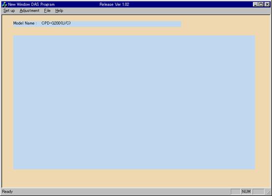
Screen 3: WIN DAS Stat Screen
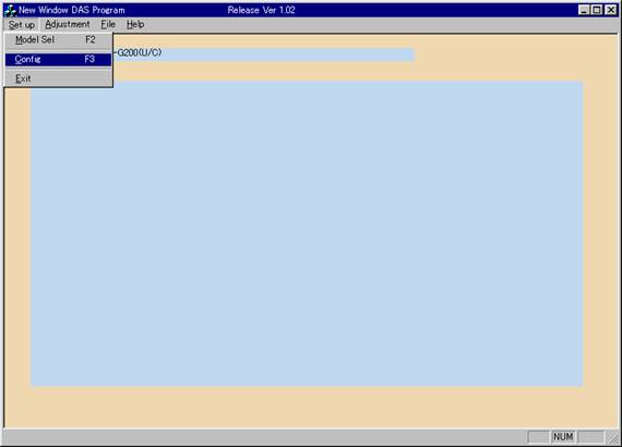
You can select Model Select Configuration and Exit from pull down menu of Set up
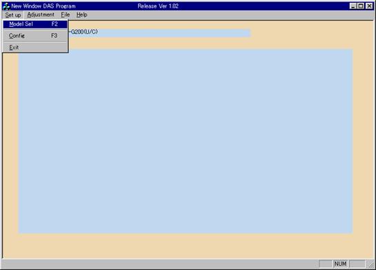
Screen 4: Set Up Pull Down Menu
To select a model you want to adjust, select Model Sel from pull down menu of Set up
You can see Model Select Dialog (Screen 5)
Double click the model name you selected then push OK button
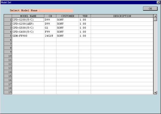
Screen 5: Model Select
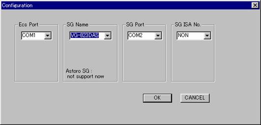
To Set up SG and connection ports, select Condig from pull down menu of Set up
You can see Model Select Dialog (Screen 5)
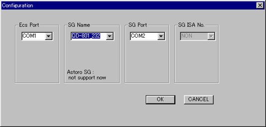
Screen 6: Configuration
Choose the port you connect ECS cable
SG NAME : It is for selection of the present SG.
Select the SG you installed.
SG PORT : It is for appointment of the port connection with external SG.
If you use external SG, choose the port you connect SG.
SG ISA No. : Choose ISA No. you establish if you install 801GF ISA
See the 5.3.1 Altering The Default Com Port for detail
To exit the WIN DAS program, you can select Exit from pull down menu of Set up.
You can select Factory preset Control SG Maintenance Touch Up Procedure
and Failure from pull down menu of Adjustment.
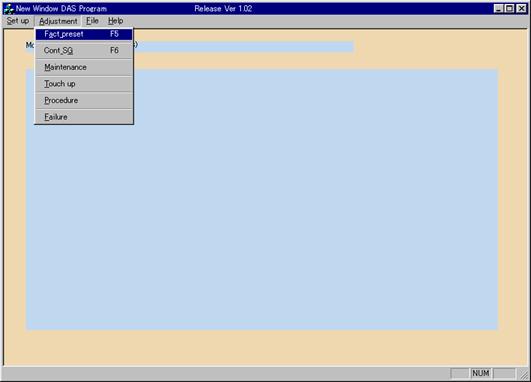
Screen 7: Adjustment Pull Down Menu
To Adjust a Deflection of Factory preset mode, select Factory_preset from pull down menu of Adjustment.
You can see Factory Preset Dialog (Screen 8)
Choose a mode by double click of mouse or number key on keyboard.
To assist you in remembering which modes you have adjusted ,the mode name will be highlighted as you select each mode with an asterisk * .
When communication is established with the monitor,the alignment data for the selected mode are read into the DAS and displayed as scrollbars on the screen.
Alignment
From the keyboard:
Use the Tab key to select the parameter to adjust. You will know when it is selected because the numeric value associated with the scroll bar will turn red. .
Use the Up/DownArrows and the PgUp/PgDn keys to perform the alignment.
Use the Tab key to select the [timing] and select mode by the Up/Down Arrows key .
Use the Tab key to select the [SAVE] button and press Enter to save the new alignment data in the monitor EEPROM.
Use the Tab key to select the [RESTORE] button if you want to restore the alignment data values to the values which were there when you entered this mode's alignment.
To change modes, press the number key ( 1 2 3 4 5 6 7 8 9 0 ) next to the mode you want to switch to.
With the mouse:
With the mouse, you perform the same steps as described above but you just point with the mouse and press the left button.
To change modes, just double click the mode you want to adjust.
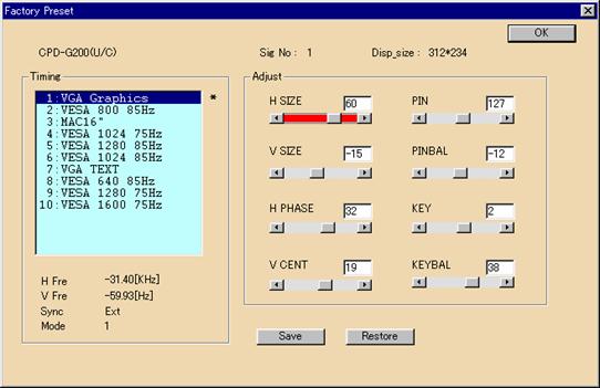
Screen 8: Factory Preset
To control Signal Generator ,select the Control SG from the Adjustment pull down menu.. The Control Signal Generator screen as Screen 9 will display.
When communications is established with the signal generator, you can choose a mode by the mouse or the keyboard for the mode you want.
When the mode is selected, the signal generator will be programmed for the correct frequencies for that mode. The pattern displayed on the screen will be the default pattern consisting of a white crosshatch. Then, you can select a different pattern and gun setup. You can make the following selections (Note: not all generators support all selections. The generator will be programmed to come as close as possible) :
Pattern
Crosshatch A crosshatch (default)
MEME The MEME pattern used for focus adjustment.
Grayscale 16 Vertical bars going from black on the left edge of the screen to
white on the right edge in 16 shades of gray
White White screen
User Patt 1 User pattern 1.
Checker Alternating pixel pattern used for Moire adjustment.
4x3 Hatch A crosshatch pattern of 12 vertical boxes and 16 horizontal boxes.
5x4 Hatch A crosshatch pattern of 16 vertical boxes and 20 horizontal boxes.
Small hatch A crosshatch pattern of 32 vertical boxes and 32 horizontal boxes Gray (30IRE) A 30% white screen
Black A 0% white screen which comes out black. Often called a 'Raster'
pattern
6% White A small white box (not necessarily square) equal to 6% of the
screen area is drawn centered on the screen
Guns
R Red gun only
G Green gun only
B Blue gun only
RGB All three guns on (default)
RB Red and Blue guns on
RG Red and Green guns on
BG Blue and Green guns on
Invert
Normal Normal Colors (default)
Invert Inverted Colors
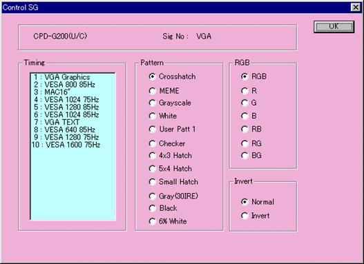
Screen 9: Control Signal Generator
Maintenance(Screen10) is only used for special operations. Normally, you should not press any buttons on this screen.
Using buttons on this screen, you can:
[Degauss] : Degauss the CRT
[Aging On] : Set Aging mode on and off
[Power On] : Turn Power on and off
This screen show you following information.
Monitor ID
The software ID, version and revision. The first two digits are the software ID, the next two are the version and revision. For example, 1234 would indicate a software ID of 12 and a version/revision of 3.4.
Factory ID
Factory ID Code(unique for each monitor model).
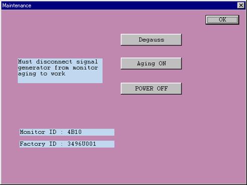
Screen 10: Maintenance
In order to modify slight distortion ,you can adjust some register you want to adjust.
(Ex. Tilt ,Pin etc..)
Push SEL button on Touch up Screen(Screen 11)to start Touch up adjustment.
otherwise push Exit button to exit Touch up Mode.
Screen 11: Touch Up
You will enter adjustment mode.(Screen 12) after push SEL button or double click.
Adjust by Scroll bar according instruction
Push OK button to go next adjustment step otherwise push CANSEL button to exit adjustment mode.
You can see signal information at bottom message box
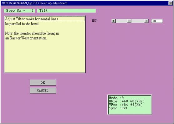
Screen 12: Adjustment mode
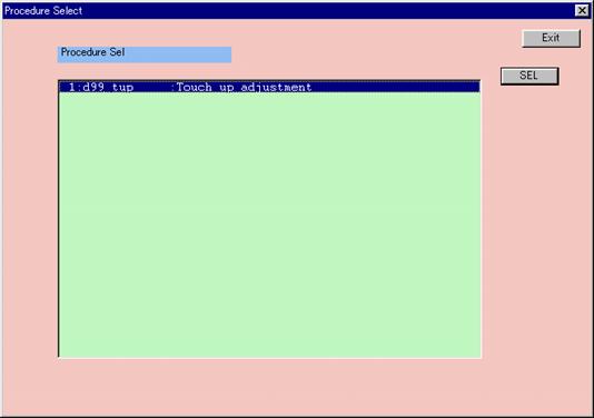
Procedures are meant to ease the adjustment of a monitor by presenting an orderly sequence of adjustment steps.
When you select Procedure from the Adjustments menu, you will be presented with a list of available adjustment procedures in a list box. Select one by double clicking the left mouse button or push SEL button.
See 7.4.1 Adjustment mode in order to know how to adjust.
As you complete each Procedure, that procedure will be moved to the bottom of the list. With this feature, you will be able to easily keep track of which procedures you have completed and if you do them in order, the next procedure to run will always be the first one in the list.
Before finishing Procedure, it is essential to do the Final setting , to be sure that the monitor has its correct initial data.
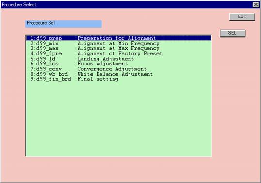
Screen 13: Procedure
This screen displays failure information. The failure status is cleared when this screen exits.
Press the [Refresh] button to refresh the failure information
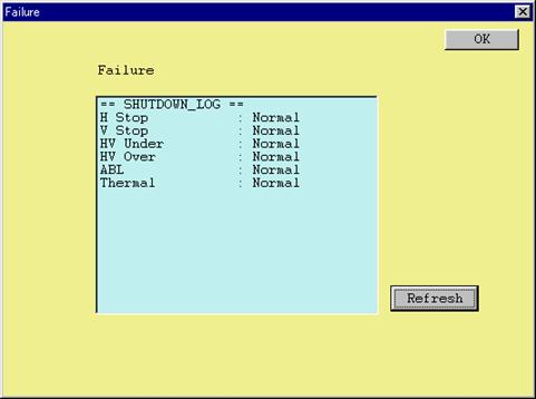
Screen 14: Failure
The possible failure are:
H Stop Scan failure shutdown by the Microprocessor Control Unit due to loss of horizontal flyback.
V Stop Scan failure shutdown by the Microprocessor Control Unit due to loss of vertical retrace.
HV Under/Over High Voltage circuit failure.
ABL ABL shutdown by the Microprocessor Control Unit or by the circuitry.
Thermal Thermal protector shutdown.
You can select Load Data to Set Save Data to File and MPU from pull down menu
of File.
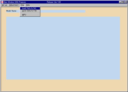
Screen 15: File Pull Down Menu
You can see File Selection box (Screen 12) when you select Load Data to Set .
Select a file you want to download from the box and push Open Button
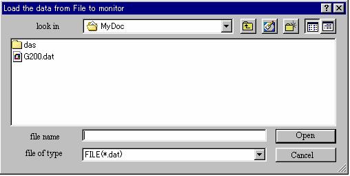
Screen 16: Selection Load Data
Screen 13 is download data screen.
Download will start when you push Go button.
You can see a progress at center window.
When download is finish,center window disappear
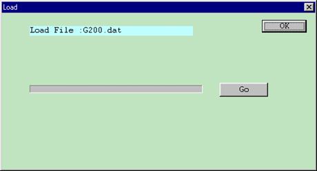
Screen 17: Download Data
This menu selection permits you to copy the complete contents of the monitor EEPROM into a disk file (Screen 14) .
Type a file name you want to save and push Save Button
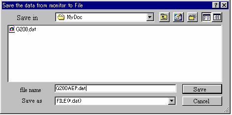
Screen 14: Save Data
Screen 15 is save data screen.
Saving will start when you push Go button.
You can see a progress at center window.
When saving is finish,center window disappear
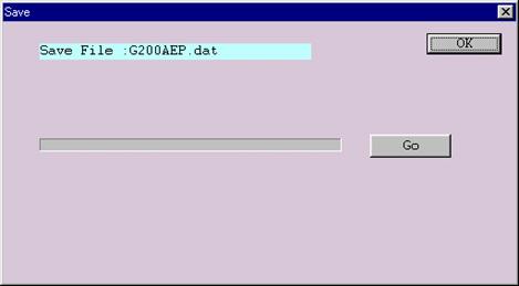
Screen 15: Save Data
This menu selection, loads the monitor EEPROM with a complete set of factory preset data from the built-in WIN DAS database.
MPU download will start when you push Go button.
You can see a progress at center window.
When MPU download is finish,center window disappear
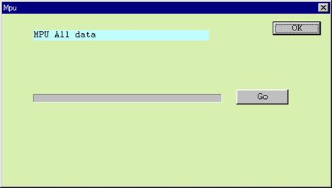
Screen 16: Save Data
You can select only Version from pull down menu of Help.
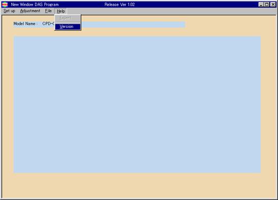
Screen 17: Help Pull Down Menu
You can find version number of WIN DAS you are using
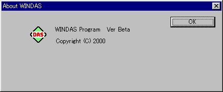
Screen 18: Version
|