ANSYS TUTORIAL
Copyright 2001-2002, John R. Baker
In this tutorial, you will model and analyze the truss below in ANSYS. Step-by-step instructions are provided beginning on the following page. This problem was adapted from Problem 6-17 in the textbook, Engineering Mechanics - Statics, Third Edition, by R.C. Hibbeler.
If you run into problems with these instructions, feel free to contact:
John Baker; Phone: 270-534-6342; Email: [email protected]
The steps that will be followed are:
Preprocessing:
1. Change Jobname.
2. Define element type. (Link1 element which is a 2-D spar)
3. Define real constants. (Area)
4. Define material properties. (Young's Modulus, EX -- only property required for this analysis)
5. Create nodes at truss joints. (8 total)
6. Create link elements between nodes. (13 total)
Solution:
7. Apply constraints and loads to the model.
8. Solve.
Postprocessing:
9. Plot deformed shape.
10. List reaction forces.
11. List a summary of element solution information, including axial forces and stresses.
12. List the deflections at each node.
13. Exit the ANSYS program.
Notes:
Cross-sectional area of
truss members = 3.0E-4 m ; Modulus of Elasticity = 2.07E11 psi; Circled numbers
shown are node numbers.
Launching ANSYS:
It is probably best to save your
work on a Zip Disk in the computer
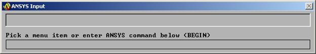
The ANSYS menus should open up. You will see a Main Menu, illustrated on the following page, and a large black graphics window. You are now ready to begin creating the model and performing the analysis.
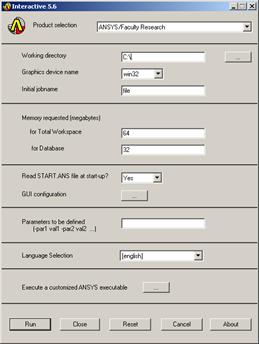
ANSYS Launcher Menu:

ANSYS Main Menu:
Note: Most of the required tasks are performed using menu picks from the ANSYS Graphical User Interface, as specified in italics in the step-by-step instructions below. The instructions below also include alternative command line entries that can be ignored if you choose to use menu picks to perform the required tasks. These are provided for your information. You may find that it is sometimes more convenient to enter certain commands directly at the command line.
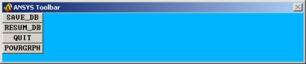 ****IMPORTANT***: AS YOU WORK THROUGH THIS EXERCISE, WITHIN
ANSYS, ON THE ANSYS TOOLBAR (UPPER RIGHT), CLICK ON "SAVE_DB" OFTEN!!! THIS TOOLBAR APPEARS AS:
****IMPORTANT***: AS YOU WORK THROUGH THIS EXERCISE, WITHIN
ANSYS, ON THE ANSYS TOOLBAR (UPPER RIGHT), CLICK ON "SAVE_DB" OFTEN!!! THIS TOOLBAR APPEARS AS:
At any point, if you want to resume from the previous time the model was saved, simply click on "RESUM_DB" on this same Toolbar. Any information entered since the last save will be lost, but this is a nice feature in the event that you make an input mistake, and are unsure of how to correct it.
There are a number of ways to model a system and perform an analysis in ANSYS. The steps below present only one method.
Preprocessing:
1. Change jobname: File -> Change Jobname
Enter "truss", and click on "OK".
Alternative Command Line Entry = /filnam, truss
Also, to enter the preprocessor, at the command line, enter: /prep7
2. Define element types: Preprocessor -> Element Type -> Add/Edit/Delete
Click on "Add , highlight "Link", then "2D spar", click on "OK", then "Close". Note that in ANSYS this element is sometimes referred to as "Link1", because it is element type 1 in the ANSYS element library.
Alternative Command Line Entry = et,1,1
3. Define the real constants for the Link1, which are cross-sectional area and initial strain:
Preprocessor -> Real Constants -> Add
Click "OK" for "Type 1 LINK1"
In this problem, there is no initial strain (leave blank), and the area is 3.0E-4. After filling in the area value, click on "OK", then "Close".
Alternative Command Line Entry = r,1,3.0E-4
4. Define Material Properties: Preprocessor -> Material Properties -> -Constant- Isotropic
"OK" for material set number 1, then enter 30E6 for EX, then "OK".
Alternative Command Line Entry = ex,1,2.07E11
5. Create nodes at truss joints: Preprocessor -> -Modeling- Create -> Nodes -> In Active CS
Enter 1 for node number (ANSYS would automatically number nodes if you leave this blank). Enter the location as (X,Y,Z)=(0,0,0). Note that we are entering the locations in meters, with node 1 located at the origin of the global x-y-z Cartesian coordinate system. Leave the entries for rotation angles blank. (Note: For this problem, all nodes will be in the X-Y plane, with Z=0). Click on "Apply". Continue defining nodes 2-8 using the locations based on the sketch of the truss, but after entering the node 8 location, click on "OK" instead of "Apply". So, node 2 is at (X,Y)=(3,0), node 3 is at (X,Y)=(6,0), node 4 is at (X,Y)=(9,0), node 5 is at (X,Y)=(12,0), node 6 is at (X,Y)=(3,3), node 7 is at (X,Y)=(6,3), and node 8 is at (X,Y)=(9,3). The dimensions entered are in inches, and on the node definition menu, for our case, rotation angles are ignored, and for all nodes, Z=0.
Alternative Command Line Entry = n
Alternative Command Line Entry = n,2,3,0,0 (or, simply: n,2,3; then similar command for all other nodes - missing input is interpreted by ANSYS as "zero" in most cases).
As a check to ensure all nodes were entered correctly, list the nodes:
Alternative Command Line Entry = nlist
If any errors were made in defining the nodes, you can redefine a node by repeating the procedure of step 5. Of course, you don't need to redefine all nodes simply to move one. Just repeat the node creation command for the incorrectly placed node.
Turn on node numbering. Utility Menu -> PlotCtrls -> Numbering. Check "node numbering", then click "OK". The node numbers may already be showing, but this will force the display of node numbers on subsequent plots.
Alternative Command Line Entry = /pnum,node,1
Create link elements between nodes:
Preprocessor -> Create -> Elements ->-Auto Numbered-Thru Nodes
A picking menu appears. Pick node 1, then node 2, and click on "Apply" in the Picking Menu. Continue creating elements using the definitions listed in the table below. After picking the nodes for the last element (element 13), choose "OK" (instead of "Apply") to define the element and close the picking menu.
Element Node I Node J
1 1 2
2 2 3
3 3 4
4 4 5
5 1 6
6 2 6
7 3 6
8 3 7
9 3 8
10 4 8
11 5 8
12 6 7
13 7 8
Alternative Command Line Entry = e
Alternative Command Line Entry = e (and so on for the remaining elements)
Solution:
If entering commands at the command line, to enter the solution processor, type: /solu
Apply constraints and forces on the model:
Solution -> -Loads- Apply -> -Structural- Displacement -> On Nodes
Pick node 5, then click "OK" in the picking menu that has appeared. Choose ALL DOF, and use the default displacement value of zero. Click on "Apply". Pick node 1, then click "OK" in the picking menu. To constrain this node in the Y-direction only, Click on "UY". Make sure to unselect the "ALL DOF" label! If the "ALL DOF" label is highlighted, unselect it by clicking on it. After confirming that only "UY" is highlighted, click "OK".
Alternative Command Line Entry = d,5,all,0
Alternative Command Line Entry = d,1,uy,0
To apply the forces, choose:
Solution -> -Loads- Apply -> -Structural- Force/Moment -> On Nodes
Pick node 2, then "OK" in the picking menu, choose "FY" as the direction of the force, and enter -125 for the force value. Click on "Apply". Pick node 3, click "OK" in the picking menu, and enter -100 for the force value (still in the FY direction). Click on "OK".
Alternative Command Line Entry = f,2,fy,-125
Alternative Command Line Entry = f,3,fy,-100
8. Solve the problem: Solution -> -Solve- Current LS
Click "OK" in the "Solve Current Load Step" Box.
Alternative Command Line Entry = solve
Postprocessing:
If entering commands at the command line, to enter the postprocessor, type: /post1
9. Plot the deformed shape: General Postproc -> Plot Results -> Deformed Shape
You will probably want to choose "Def + undeformed", then "OK".
Alternative Command Line Entry = pldi
10. List reaction forces: General Postproc -> List Results -> Reaction Solution
Click on "All struc forc F", and "OK".
Alternative Command Line Entry = prrf
You might want to print the information in the Listing Box, by clicking, in that box, on "File -> Print". Or else, just write the information down.
11. List a summary, which includes the axial force and stress in each element:
Click "OK", and a summary for each element is printed, including the node numbers, from which you can identify the corresponding truss member, and also the axial force (MFORX), and the axial stress (SAXL). You may want to either record, or print, this information.
12. List the x and y direction deflections for each node:
Click "OK". Again, you may want to either record, or print, this information.
Alternative Command Line Entry = prdi
13. Exit ANSYS. Toolbar: Quit ->Save Everything -> OK
|
