Revision 0, January 17
Cam Phaser System - 6 Cylinder, 1
Figure
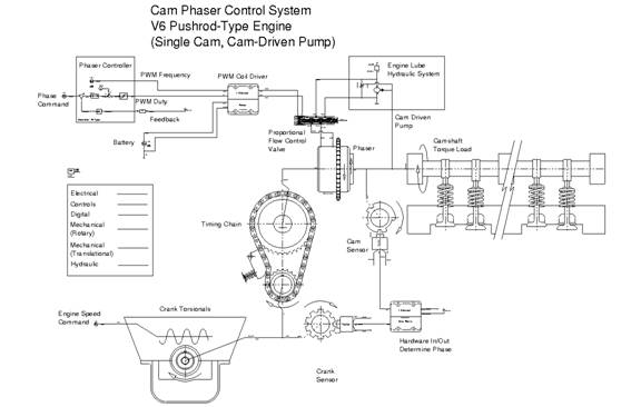
This example illustrates the use of the Cam Phaser library elements as applied in a complete control system model. The engine modeled is a typical pushrod 24324u2017y -type V6 engine with a single camshaft. The system includes several "plant" models to provide realistic boundary conditions in terms of torsional crank snout displacements and timing chain and camshaft load dynamics. The engine hydraulic system provides realistic load-flow capacity available to the hydraulic vane phaser. Speed sensor models provide accurate digital information regarding speed and position of both the crank and cam. The sensor signals are processed additionally to provide realistic cam phase measurements used as feedback to the controller. A simple PI controller is used to process the desired or commanded cam phase angle based on error determined by the feedback signal. The controller output drives the phaser control valve through a PWM "high-side" coil driver. The driver has capability to vary both PWM duty cycle and frequency based on signals from the controller.
The basic system example uses the following top-level inputs to generate the system simulation cycle:
a. The engine speed is initialized at zero and rises to 6000 RPM using an exponential source. The tau for rising is set to 0.1 seconds, as is the tau for falling. The engine speed stays constant at 6000 RPMs for the duration of the 5 second simulation time.
b. The cam phase command uses a PWL control source with a varying signal versus time.
c. The temperature and associated engine oil properties are set to 20° C.
The following plots shows both of these inputs for the basic simulation run.

Figure Basic System Inputs
The basic example circuit should be loaded into SaberSketch, where the model parameters for all of the components can be viewed, and if desired, changed to test different engine speed and cam phase command cycles. The design can then be loaded into Saber for simulation using the forms or .scs files provided. After simulation the interesting signals can be viewed in Saber Sketch and processed using measurements, etc.
The forms and .scs files include both a single 5 second transient run where the engine speed is ramped up to 6000 RPM, and a Vary Loop that sweeps through speeds from 1000 to 6000 RPM in 1000 RPM increments. The Vary loop runs the transient for 1 second which is long enough to see the first major command change and response of the cam phase. The relevant forms and .scs files are as follows:
Single Transient Run
a) Forms file, "Example_Phaser.ai_frm"
b) SCS file, "Example_Phaser_tr_only.scs"
Vary
a) Forms file, "Example_Phaser.ai_frm"
b) SCS file, Example_Phaser_tr_vary.scs"
The signals of interest can be grouped into several categories based on portions of the system model that relate to plant model contribution, feedback sensors, phaser and control valve characteristics, as well as the controller.
The plant-type models are utilized to provide realistic steady state and dynamic loads on the phaser component so that system control can be evaluated. Items related to the crankshaft torsional input, characteristics of the timing chain, torque loading due to the valve train and oil pump loads on the camshaft, and the hydraulic supply capacity are all boundary conditions that affect the phaser and related control system performance.
The crank torsional inputs to the timing chain are characterized by small angular deflections during each engine cycle that are based on the firing of cylinders and the related crank reactions to those events. The crank torsional, as well as the cam loading and vane phaser reactions can be seen below in comparisons of node signals for the crank speed (w_crank) and cam speed. (w_cam)
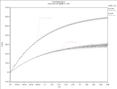
Figure 3 Plant Model
Effects - Crank and
The speed sensors used to measure crank and cam angles that are used ot process into effective cam phase measurements. The crank and cam sensor outputs relate the 0-360 degree cyclic behavior of each, updated based on speed sensor target wheel teeth locations. The crank and cam sensor outputs are shown in the following figures.
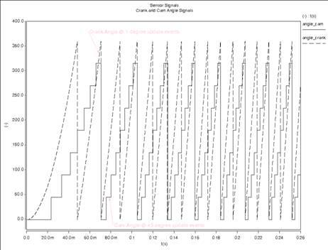
Figure Crank and
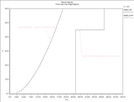
Figure Zoom0In Showing Sensor Updates
The output sensor values are processed to provide the relative phase of the cam that is used as feedback to the position control system. The system used for this example has a "reverse" vane phaser which retards the cam relative to the crank as the phaser displaces from the home or "Park" position. The cam phase signal is therefore negative. The controller, however, works with positive values for both command and feedback such that increased phase is "away from Park" regardless of the actual polarity. The cam phase signal is therefore processed again to obtain the absolute value, which is then fed into the control loop as feedback. The follow plots shows the actual phase measurement, the absolute value result, as well as the basic command input to the controller.
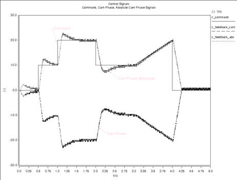
Figure Basic Control signal
|
