SCREEN-TEST-LINE 7000
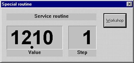
Service Routine
CONTENTS
Entering the Service Routine
Display cabinet with keypad
PC with STL7000 Software
Entering the Code
Changing the Test Steps
Modifying Specified Values
Limit Table
Test Steps
MICRO-BRAKE 6000
MICRO-SWING 6200
MICRO-SIDE-SLIP 6300
MICRO-TOE-ANGLE 6400
Micro-SAT 6600
Step 4 - Zero point for left vibration plate (car positioning aid)
Step 8 - Zero point for right vibration plate (car positioning aid)
Step 30 - check the increment generator
Step 31 - check the frequency converter parameters
Step 32 - check the frequency stability
Printing Configuration and Calibration Data
If an analog display cabinet is connected to the system, you must observe the following prior to entering the service routine:
|
|
Turn the main switch of the test line to off Turn the main switch of the test line to on Hold down the RIGHT-ON button in the display cabinet during start-up until the request to enter the code appears on the LCDs |
The LCD display on the left of the display cabinet is deleted and two horizontal dashes appear in the display on the right.
The red and green pointers both remain at the left-hand stop.
You must now enter the code as described in Section 2.
General information about the service routine
The analog display for the right side (red pointer) indicates the current step.
The analog display for the left side (green pointer) indicates the current value.
The 4-digit LCD display on the left (optional) shows the current value.
The 2-digit LCD display on the right (optional) shows the test step.
Turn the main switch of the test line to off
Turn the main switch of the test line to on
The user now has 6 seconds to select one of the following special programs from the window that appears.
4. Please press Service.
|
Figure |
Before you can set the test steps, you must enter the code below in this window:
Remote control buttons:
|
|
Figure LCD display cabinet " - " is displayed each time the button is pressed.
Figure Display STL7000 " * " is displayed each time the button is pressed. |
|
|
Entry is deleted Enter new code |
Initialization of the test line is then continued if the suspension tester and sideslip plate are integrated in the system.
|
|
next step |
|
|
previous step |
You can enter these commands either by remote control or via the keypad!
|
|
Select the desired test step (also possible via keypad) |
|
|
Enter appropriate value |
|
|
Confirm the specified value |
The figure below shows the text step on screen and the associated setting or value:

|
Figure PC display window

Figure LCD display cabinet
|
Slip frequency
roller/position roller - |
25 - 250 digits (100 digits) |
|
Slip frequency
roller/position roller - |
251 - 1000 digits (900 digits) |
|
Zero points for brake force, weight, vibration plates and PD |
25 - 250 digits (100 digits) |
|
Zero point for side-slip tester |
300 - 700 digits (600 digits) |
|
Calibration check |
750 - 980 digits (850 digits) |
|
Calibration value for brake force (maximum value) |
6.000 N |
|
Calibration value for weight (maximum value) |
2.000 kg (per side) |
|
Calibration value for PD (maximum value) |
1000 N |
|
Calibration value for vibration plate (maximum value) |
2.000 kg (per side) |
|
Calibration value for sideslip tester |
actual deflection [mm] |
|
Zero point for turntable (MTA 6400) |
950 - 970 digits (959 digits) |
Values given in brackets () are suggestions for default values!
01 = Date (Day.Day.Month.Month)
02 = Date (Year.Year.Year.Year)
03 = Time (Hour.Hour.Minute.Minute)
04 = Left slip sensor (display value changes when you turn the slip frequency roller)
05 = Right slip sensor (display value changes when you turn the slip frequency roller)
06 = Left position roller (display value changes when you press down the position roller)
07 = Right position roller (display value changes when you press down the position roller)
08 = Zero point for left brake force sensor [digit]
09 = Calibration check for left brake force sensor [digit]
10 = Physical value for left brake force [N]
11 = Physical value for left brake force with calibration check [N] (= 6.000 N)
12 = Zero point right brake force sensor [digit]
13 = Calibration check for right brake force sensor [digit]
14 = Physical value for right brake force [N]
15 = Physical value for right brake force with calibration check [N] (= 6.000 N)
16 = Zero point for left weight [digit]
17 = Calibration check for left weight [digit]
18 = Physical value for left weight [kg]
19 = Physical value left weight with calibration check [kg] (= 2.000 kg)
20 = Zero point for right weight [digit]
21 = Calibration check for right weight [digit]
22 = Physical value for right weight [kg]
23 = Physical value for right weight with calibration check [kg] (= 2.000 kg)
24 = Zero point for PD [digit]
25 = Calibration check for PD [digit]
26 = Physical value for PD [N]
27 = Physical value for PD with calibration check [N] (= 1000 N)
Notes on pedal force:
Test steps for PD a called only when the sensor is connected!
If the forces sensor is loaded with a weight in [kg], the actual weight must be entered in [N] per remote control in Step.
Formula for computation in Germany: 1kg * 9.81kgm/s2 = 9.81 N
01 = Date (Day.Day.Month.Month)
02 = Date (Year.Year.Year.Year)
03 = Time (Hour.Hour.Minute.Minute)
04 = Zero point for left vibration plate [digit]
05 = Calibration check for left vibration plate [digit]
06 = Physical value for left vibration plate [kg]
07 = Physical value for left vibration plate with calibration check [kg] (= 2.000 kg)
08 = Zero point for right vibration plate [digit]
09 = Calibration check for right vibration plate [digit]
10 = Physical value for right vibration plate [kg]
11 = Physical value for right vibration plate with calibration check [kg] (= 2.000 kg)
01 = Date (Day.Day.Month.Month)
02 = Date (Year.Year.Year.Year)
03 = Time (Hour.Hour.Minute.Minute)
04 = Zero point for sideslip tester [digit]
05 = No input possible
06 = Physical value for sideslip tester [mm] (actual deflection)
07 = No input possible
01 = Date (Day.Day.Month.Month)
02 = Date (Year.Year.Year.Year)
03 = Time (Hour.Hour.Minute.Minute)
04 = Zero point for left turntable [digit]
05 = No input possible
06 = Physical value for left turntable [O]
07 = No input possible
08 = Zero point for right turntable [digit]
09 = No input possible
10 = Physical value for right turntable [O]
11 = No input possible
01 = Date (Day.Day.Month.Month)
02 = Date (Year.Year.Year.Year)
03 = Time (Hour.Hour.Minute.Minute)
04 = Zero point for left vibration plate [digit]
05 = Calibration check for left vibration plate [digit]
06 = Physical value for left vibration plate [kg]
07 = Physical value for left vibration plate with Calibration check [kg] (= 2.000 kg)
08 = Zero point for right vibration plate [digit]
09 = Calibration check for right vibration plate [digit]
10 = Physical value for right vibration plate [kg]
11 = Physical value for right vibration plate with calibration check [kg] (= 2.000 kg)
Help functions for diagnostics
30 = Check increment generator (separately for left and right side)
31 = Check frequency converter parameters (separately for left and right side)
32 = Check frequency stability (separately for left and right side)
In these steps, the zero point of the shear force sensor is displayed in digits. This value should lie within the specified limits:
|
Zero points for vibration plates |
60 - 250 digits (100 digits) |
Press the ENTER key to deactivate the intelligent sensor; press it again to re-activate it.
Display on PC:
Display at display cabinet:
When the intelligent sensor is activated, the middle LED block or the difference display lights up.
Note:
When the sensor is deactivated, the zero point should be roughly half the value. If this is not the case, the sensor is either defective or no intelligent sensor is installed.
Tolerance: >30 digits after halving the measuring signal
Please them observe the following procedure:
1. Vibration plate is clamped
Loosen the screws that fasten the vibration plate and tighten them again using a torque wrench. The check the zero points again. When the intelligent sensor is deactivated, the zero point must be almost half the value.
If there is no distinct improvement, see point 2 below.
2. Force sensors clamped and installed
Remove the vibration plate and de-mount the force sensors. Then check the zero points again under absolutely no load. When the intelligent sensor is deactivated, the zero point must be almost half the value.
Result OK:
Install the force sensors properly centered and make sure that there is no dirt on the surface. Then check the zero points again.
Result still incorrect:
- Force sensors are defective (notify the manufacturer)
- PC board defective (change the processor)
- Check cable
The program control can use this function to operate the left and right motors of the shock absorber tester in open-loop mode between 100 rpm and 600 rpm.
In this case, the increment generator signals from the frequency converter are not used to compensate the speed, but are input as actual frequency value and the deviation compared to the setpoint speed computed. The slip value obtained is shown in the display.
Each revolution runs through the zero channel and is accumulated. The user is thus able to detect the speed-dependent increase in the number of zero channels, which are output to the display.
e.g.: Checking the left side:
|
|
Start left side The engine starts to move the vibration plate at 100 rpm. |
|
Check zero channel The value on the left-hand display must increase with the speed |
|
|
|
Increase speed The speed increases by 100 rpm. each time the button is pressed. |
|
|
Stop Switch off engine and exit the process. |
The above description applies analogously when checking the right side.
The program control can use this function to operate the left and right motor of the shock absorber tester in open-loop mode between 100 rpm and 600 rpm.
The current run-time parameters of the frequency converter are displayed in a special overview window. The monitor of the service routine displays the actual speed.
Overview of parameters:
e.g.: Checking the left side:
|
|
Start left side The motor starts to move the vibration plate at 100 rpm. |
|
Update of run-time parameters in the STL7000 overview window |
|
|
|
Increase speed The speed increases by 100 rpm. each time the button is pressed. |
|
|
Stop Switch off engine and exit the process |
The above description applies analogously when checking the right side.
The program control can use this function to operate the left and right motor of the shock absorber tester in regulated mode between at 600 rpm (=10 Hz).
The electronics in the sensor check the pulse lengths recorded for the channels of the increment generator and computes the mean deviation for the speed as a percentage per revolution.
Value range: 0...6 % Standard condition
>6 % Strong effect on results of measurement
If the deviation in speed lies outside the tolerance, one the following may be the cause:
Poor mechanical quality.
Irregularities or rounding in the increment generator signals.
Setting the frequency converter parameters.
e.g.: Checking the left side:
|
|
Start left side Motor starts to move the vibration plate at 600 rpm. |
|
Display of quality as a percentage |
|
|
|
Increase speed The speed increases by 600 rpm. each time the button is pressed. |
|
|
Stop Switch off engine and exit the process |
The above description applies analogously when checking the right side.
|
|
Press one of the three buttons |
You can output the data to the printer at any step in the service routine!
SCREEN-TEST-LINE 7000
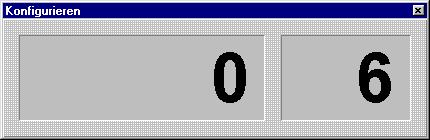
Konfigurationsroutine
INHALTSVERZEICHNIS
Eintritt in die Konfigurationsroutine
Code - Eingabe
Umschalten der Prüfschritte
Ändern der vorgegebenen Werte
Prüfschritte - Gesamtübersicht
Prüfschritte - mit Erläuterungen
Ausdruck der Konfigurations- und Kalibrierdaten
Codierung der IR-Fernbedienung
Allgemeines
Codierung der Anlage
Fernbedienung
Prüfstand
Prüfstand mit Hauptschalter auf aus
Prüfstand mit Hauptschalter auf ein
Der Anwender hat ca. 6 Sekunden zeit, eines der folgenden Sonderprogramme in dem eingeblendeten Fenster anzuwählen.
4. Bitte die Schaltfläche Konfig anwählen.
|
Abbildung |
Analoger Anzeigeschrank
Wenn ein analoger Anzeigeschrank dem System angeschlossen ist, muß für den Eintritt in die Serviceroutine folgendes beachtet werden:
|
|
Prüfstand mit Hauptschalter auf aus Prüfstand mit Hauptschalter auf ein AUTOMATIK-Taste am Anzeigeschrank während der Einschaltphase gedrückt halten, bis auf den LCD's die Aufforderung für die Codeeingabe angezeigt wird |
An der LCD-Anzeige des Anzeigeschrankes wird die linke LCD-Anzeige gelöscht und auf der rechten erscheinen zwei waagrechte Striche.
Der rote und grüne Zeiger stehen beide auf dem linken Anschlagspunkt.
Dann muß die Code-Eingabe erfolgen, die im Punkt 2 berschrieben ist.
Allgemeines zur Konfigurationsroutine
Die Analoganzeige für die rechte Seite (roter Zeiger) gibt den aktuellen Schritt an.
Die Analoganzeige für die linke Seite (grüner Zeiger) zeigt den aktuellen Wert an.
Die linke 4-stellige LCD-Anzeige (Option) weist den aktuellen Wert aus.
Die rechte 2-stellige LCD-Anzeige (Option) gibt den Prüfschritt aus.
Um die Prüfschritte einstellen zu können, muß der unten aufgeführte Code in diesem Fenster eingegeben werden:
Fernbedienungstasten:
|
|
Abbildung |
|
|
Eingabe wird gelöscht Code neu eingeben |
Danach wird die Initialisierung der Prüfstraße fortgeführt, falls Fahrwerktester und Spurplatte mit im System integriert sind.
|
|
nächster Schritt |
|
|
vorheriger Schritt |
Diese Befehle sind sowohl mit der Fernbedienung, als auch mit dem Tastenfeld möglich!
|
|
gewünschten Prüfschritt wählen (auch mit Tastenfeld möglich) |
|
|
gewünschten Wert eingeben |
|
|
eingegebenen Wert bestätigen |
Folgende Abbildung zeigt am Bildschirm den Prüfschritt und die zugehörige Einstellung bzw. Wert:

 Beispiel: Sprache = 0
|
Abbildung |
01 = Gesetzlicher Wert für Differenz Betriebsbremse
02 = Gesetzlicher Wert für Gesamtabbremsung Betriebsbremse
03 = Gesetzlicher Wert für Gesamtabbremsung Feststellbremse
04 = Gesetzlicher Wert für Unrundheit
05 = Schlupfgrenze
06 = Sprachenauswahl
07 = Ausgleich mechanische Toleranz Analoganzeige linke Seite
08 = Ausgleich mechanische Toleranz Analoganzeige rechte Seite
09 = Eingabe Werkstattadresse für Ausdruck
(nur mit PC möglich - Bedienung siehe Beschreibung PC-Visualisierung)
10 = Definition der Prüfstandsreihenfolge (Anzeige erfolgt an der linken LCD)
11 = Sonderversionen
12 = Gesetzlicher Wert für Differenz Feststellbremse
13 = Gesetzlicher Wert für Differenz Hilfsbremse (Italien)
14 = Gesetzlicher Wert für Gesamtabbremsung Hilfsbremse (Italien)
15 = Nennfrequenz der Schlupfrollen (Defaultwert: 37 Hz)
16 = Eingabe Infrarot-Adresse (0 - 10)
17 = Gesetzlicher Wert für Gesamtabbremsung Betriebsbremse LLKW (Polen)
18 = Gesetzlicher Wert für Gesamtabbremsung Betriebsbremse BUS (Polen)
19 = Endauswertung Fahrwerkstester ausdrucken (0 = nein, 1 = ja = Default)
20 = Gesetzlicher Wert für maximale Pedalkraft PKW (Polen)
21 = Gesetzlicher Wert für maximale Pedalkraft BUS (Polen)
22 = Gesetzlicher Wert für maximale Pedalkraft LKW bis 3.5t (Polen)
23 = Spurwert für den Beginn des gelben Bereichs (Defaultwert 3mm)
24 = Spurwert für den Beginn des roten Bereichs (Defaultwert 6mm)
25 = Druckerauswahl (Defaultwert: 1= Seikosha SP-2400)
26 = MESRA Pedalkraft-Set 1 = MESRA PD1 (Defaultwert)
2 = MESRA PD2
01 = Gesetzlicher Wert für Differenz Betriebsbremse
Gesetzlicher Wert: Defaultwert= 25 %
02 = Gesetzlicher Wert für Gesamtabbremsung Betriebsbremse
Gesetzlicher Wert: Defaultwert= 50 %
(52 % bei Sonderversion Polen)
03 = Gesetzlicher Wert für Gesamtabbremsung Feststellbremse
Gesetzlicher Wert: Defaultwert= 20 %
(16 % bei Sonderversion Polen)
04 = Gesetzlicher Wert für Unrundheit
Gesetzlicher Wert: Defaultwert= 25 %
05 = Schlupfgrenze
Unter Schlupf versteht man die Differenz der Drehzahl der Tastrolle zur Nenndrehzahl der Bremsrolle.
Ist die Schlupfgrenze auf den Defaultwert von 25% festgelegt, so schaltet der Prüfstand ab, wenn die Drehzahl der Tastrolle um 25% unter der des Rollensatzes liegt.
Hohe Bremskräfte oder nasse Reifen können das "Durchrutschen des Reifens" beim Bremsen hervorrufen.
Ein Herabsetzen des Wertes (<25%) kann zu einem frühzeitigen Abschalten der Anlage führen.
Ein Heraufsetzen des Wertes (>25%) kann zu einem starkem Abrieb des Reifen-profils führen.
06 = Sprachenauswahl
|
Druckerserver EPROM | |
|
0 = Deutsch |
10 = Polnisch |
|
1 = Englisch |
11 = Portugiesisch |
|
2 = Französisch |
12 = Finnisch |
|
3 = Spanisch |
13 = Estnisch (noch nicht vorhanden) |
|
4 = Griechisch |
14 = Brasilianisch/Portugisisch |
|
5 = Norwegisch |
15 = Ungarisch |
|
6 = Tschechisch | |
|
7 = Holländisch/Belgisch | |
|
8 = Italienisch | |
|
9 = Kroatisch |
07 = Ausgleich mechanische Toleranz Analoganzeige linke Seite
08 = Ausgleich mechanische Toleranz Analoganzeige rechte Seite
Bedingt durch den mechanischen Anschlag und dem Getriebe der Schrittmotore, unterliegt die Analoganzeige einer Toleranz, die mit Hilfe der Konfigurationsschritte 7 und 8 ausgeglichen werden kann. Dadurch ist es möglich, die Ablesegenauigkeit zu erhöhen.
Der Toleranzausgleich wird wie folgt vorgenommen:
|
|
gewünschten Schritt wählen (auch mit Tastenfeld möglich) |
|
|
Taste so oft betätigen, bis sich der entsprechende Zeiger vom Anschlag abhebt |
|
|
Eingabe bestätigen |
Diese Eingaben werden werkseitig vorgenommen und müssen deshalb in der Regel nicht mehr verändert werden!
09 = Eingabe Werkstattadresse für Ausdruck
(nur mit PC möglich - Bedienung siehe Beschreibung PC-Visualisierung)
10 = Definition der Prüfstandsreihenfolge (Anzeige erfolgt an der linken LCD)
Nummern der Prüfstände:
|
Bremsenprüfstand |
||
|
Fahrwerktester |
||
|
Spurprüfplatte |
||
|
Spurdifferenzwinkel-Meßgerät |
||
|
nicht vorhanden |
Beispiel: Prüfstraße in der Reihenfolge Spur - Fahrwerk - Bremse
|
1. Gerät (Spur) |
2. Gerät (Fahrwerk) |
3. Gerät (Bremse) |
4. Gerät (nicht vorh.) |
11 = Sonderversionen
Da in diversen Ländern andere gesetzliche Grundlagen über die Auswertung von Bremsprüfstandsresultaten existieren, können hier spezielle länderspezifische Eigenschaften ausgewählt werden.
Nummern der Sonderversionen:
|
Standard | |||
|
Schweiz |
Im Ausdruck erscheinen die Bremskräfte um den Faktor 0,83 verringert, gegenüber den Bremskräften auf der Anzeige. |
||
|
Holland |
Die Abbremsung wird in m/s2 berechnet. |
||
|
Frankreich |
Die Bremskräfte werden in daN ausgedruckt. 1 daN = 10 N |
||
|
Italien |
Die Änderungen sind in einer speziellen Bedienungs-anleitung dokumentiert. |
||
|
Polen |
Die Änderungen sind in einer speziellen Bedienungs-anleitung dokumentiert. |
||
|
Bremskraft"8000N" |
Software und Bedienung Keine veränderten Testabläufe gegenüber der Standardversion Nr.0 Hinweis: Die STL7000 V5.3 erlaubt keine Auswertung und Anzeige der Bremskräfte über 6000N. Bei der nächsten Überarbeitung wird dieses Problem behoben. Mechanik 5 kW Motoren stärkere Antriebsketten Sensorik Spezial Scherkraftaufnehmer BFS 106, Meßbereich 1mA.....9mA 656 KG Rotes Isolierband über DMS-Taschen dient als Erkennung Max. Belastbarkeit der Anordnung (mit Hebelverhältnissen) = 7500N Anzeige Analoganzeigeschrank mit neuer Bremskraftskala (Endwert= 8kN) |
Hinweis:
Falls im Programm gesetzliche Grenzwerte für eine Sonderversion hinterlegt sind, werden diese beim Abspeichern der Sonderversion im Speicher abgelegt.
Eine Überprüfung wird aber empfohlen, da aktuelle Änderungen nicht sofort ins Programm einfließen.
Beim Bestätigen der Version 0 = Standard, werden die in Deutschland geltenden Defaultwerte übernommen.
12 = Gesetzlicher Wert für Differenz Feststellbremse
13 = Gesetzlicher Wert für Differenz Hilfsbremse (Italien)
Dieser Konfigurationsschritt ist nur von Bedeutung, wenn die Sonderversion 4 - "Italien" im Schritt 11 eingestellt ist.
14 = Gesetzlicher Wert für Gesamtabbremsung Hilfsbremse (Italien)
Dieser Konfigurationsschritt ist nur von Bedeutung, wenn die Sonderversion 4 - "Italien" im Schritt 11 eingestellt ist.
15 = Nennfrequenz der Schlupfrollen (Defaultwert: 37 Hz)
In diesem Prüfschritt kann die Frequenz des Schlupfsensorsignals im Leerlauf (ohne Bremsbelastung) eingegeben werden.
Der Wert ist im Betrieb am 50Hz-Drehstromnetz für den Standardrollensatz auf 37 Hz festgelegt.
16 = Eingabe Infrarot-Adresse (0 - 10)
Die Vorgehensweise ist im Punkt 9. Codierung der IR-Fernbedienung beschrieben.
17 = Gesetzlicher Wert für Gesamtabbremsung (Polen)
Betriebsbremse LKW bis 3,5 t
Dieser Konfigurationsschritt ist nur von Bedeutung, wenn die Sonderversion 5 - "Polen" im Schritt 11 eingestellt ist.
Gesetzlichen Werte für die Gesamtabbremsung: Defaultwert= 40 %
18 = Gesetzlicher Wert für Gesamtabbremsung Betriebsbremse BUS (Polen)
Dieser Konfigurationsschritt ist nur von Bedeutung, wenn die Sonderversion 5 - "Polen" im Schritt 11 eingestellt ist.
Gesetzlichen Werte für die Gesamtabbremsung: Defaultwert= 45 %
19 = Endauswertung Fahrwerkstester ausdrucken
Endauswertung ausdrucken: 1 (Default)
Endauswertung nicht ausdrucken: 0
20 = Gesetzlicher Wert für maximale Pedalkraft PKW (Polen)
Dieser Konfigurationsschritt ist nur von Bedeutung, wenn die Sonderversion 5 - "Polen" im Schritt 11 eingestellt ist.
gesetzlichen Pedaldruck-Abschaltgrenzen: Defaultwert= 50 daN
21 = Gesetzlicher Wert für maximale Pedalkraft BUS (Polen)
Dieser Konfigurationsschritt ist nur von Bedeutung, wenn die Sonderversion 5 - "Polen" im Schritt 11 eingestellt ist.
gesetzlichen Pedaldruck-Abschaltgrenzen: Defaultwert= 70 daN
22 = Gesetzlicher Wert für maximale Pedalkraft LKW bis 3.5t (Polen)
Dieser Konfigurationsschritt ist nur von Bedeutung, wenn die Sonderversion 5 - "Polen" im Schritt 11 eingestellt ist.
gesetzlichen Pedaldruck-Abschaltgrenzen: Defaultwert= 70 daN
23 = Spurwert für den Beginn des gelben Bereichs Defaultwert= 3mm
24 = Spurwert für den Beginn des roten Bereichs Defaultwert= 6mm
Diese Konfigurationsschritte ermöglichen dem Anwender eine freie Zuordung der Farben für die Darstellung der Spurwerte. Die Grenzwerte müssen ganze Zahlen zwischen 0...15 mm sein.
Ist der Spurwert für den Beginn des roten Bereichs >7mm, so beträgt der Maximalwert 16mm.
Ist der Spurwert für den Beginn des roten Bereichs >12mm, so beträgt der Maximalwert 20mm.
Die positiven Spurwerte werden auch für den negativen Bereich übernommen.
Standardmäßig sind folgende Defaultwerte eingegeben:
![]()
+6 +3 -3 -6 -12
0 mm
25 = Druckerauswahl
0 = Druckertyp Olivietti DM109 (oder andere)
1 = Druckertyp Seikosha SP-2400
Diese Einstellung ist nur von Bedeutung, falls der Drucker am Prüfstand angeschlossen ist.
Der Ausdruck über die STL7000 wird durch diesen Konfigurationsschritt nicht beeinflußt.
26 = Auswahl MESRA Pedalkraft-Set
Wenn mehrere Prüfstraßen in einer Werkstatt betrieben werden, ist es notwendig, daß jeder Anlage eine unterschiedliche Frequenz für die Pedaldruckmessung zugeordnet wird. Nur bei der Verwendung von unterschiedlichen Pedalkraft-Sets ist ein gleichzeitiger Betrieb möglich.
Jeder Prüfstand empfängt dann nur den Pedalkraftwert, der mittels des ausge-wählten Kanales bzw. der Frequenz konfiguriert ist.
Maximal Anzahl: 1 = MESRA PD1 (default)
2 = MESRA PD2
3 = MESRA PD3
4 = MESRA PD4
|
|
eine der drei Tasten betätigen |
Die Daten können in einem beliebigen Schritt der Konfigurationsroutine auf den Drucker ausgegeben werden!
Falls mehrere Prüfstraßen oder Einzelprüfstände in einer Halle genutzt werden sollen, ist es notwendig die Fernbedienungen unterschiedlich zu codieren, um eine gegenseitige Beeinflussung der Prüfstände zu vermeiden.
Hierbei sind 11 Varianten einstellbar (Default ist 0).
Die Codierung kann folgendermaßen verändert werden:
|
Batterie aus Fernbedienung entnehmen |
|
|
Batterie wieder einsetzen |
|
|
|
5x hintereinander die STOP-Taste betätigen |
|
|
Innerhalb von 5 Sekunden die gewünschte Adresse eingeben; z.B.: Adresse 4 |
|
Erfolgt zu einem späteren Zeitpunkt wieder ein Batteriewechsel, so ist die Adressierung wieder vorzunehmen, falls die gewünschte Adresse nicht 0 ist |
Adresstabelle:
|
|
Adresse 1 |
|
|
Adresse 2 |
|
|
Adresse 3 |
|
|
Adresse 4 |
|
|
Adresse 5 |
|
|
Adresse 6 |
|
|
Adresse 7 |
|
|
Adresse 8 |
|
|
Adresse 9 |
|
|
Adresse 10 |
In der Konfigurationsroutine den Schritt 16 wählen. Auf der 4-stelligen LCD erscheint dann rechts der eingestellte bzw. eingegebene Wert. Links blinkt kurzzeitig bei jeder Eingabe mit der Fernbedienung deren Code.
Wie bei den anderen Konfigurationsschritten gewohnt, wird auch hier der gewünschte Wert eingegeben und mit "ENTER" bestätigt.
Anmerkung:
Im Normalbetrieb reagiert nun der Prüfstand nur noch auf Fernbedienungs-kommandos mit der konfigurierten Adresse. In den Sonderroutinen hingegen wird die Adresseinstellung nicht berücksichtigt.
SCREEN-TESTLINE 7000
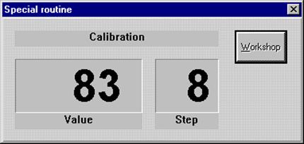
Calibration Routine
CONTENTS
1 Entering the Calibration Routine
1.1 Display cabinet with keypad
1.2 PC with STL7000 Software
2 Entering the Code
3 Changing the Test Steps
4 Modifying Specified Values
5 Explanation of the Calibration Principle
5.1 General
5.2 Zero point - Step 1
5.3 Calibration check - Step 2
5.4 Physical value - Step 3
5.5 Physical value with calibration check - Step 4
6 Limit Table
7 Test Steps
7.1 MICRO-BRAKE 6000
7.2 MICRO-SWING 6200
7.3 MICRO-SIDE-SLIP 6300
7.4 MICRO-TOE-ANGLE 6400
7.5 Micro-SAT 6600
7.5.1 Explanations for test steps 4 and 8
7.5.2 Explanations for test steps 30, 31 and 32
7.5.3 Step 30 - Open-loop test
7.5.4 Step 31 - Regulated test run
7.5.5 Step 32 - Vibration plate compensation
8 Printing Configuration and Calibration Data
If an analog display cabinet is connected to the system, the following points must be observed before entering the calibration routine:
|
|
Turn the main switch of the test line to off Turn the main switch of the test line to on Hold down the LEFT-ON button at the display cabinet during the start-up phase until the request to enter the code appears on the LCDs. |
The LCD display on the left of the display cabinet is deleted and two horizontal dashes appear in the display on the right.
The red and green pointers both remain at the left-hand stop.
You must now enter the code as described in Section 2.
General information about the calibration routine
The analog display for the right side (red pointer) indicates the current step.
The analog display for the left side (green pointer) indicates the current value.
The 4-digit LCD display on the left (optional) shows the current value.
The 2-digit LCD display on the right (optional) shows the test step.
7. Turn the main switch of the test line to off
8. Turn the main switch of the test line to on
9. The user now has 6 seconds to select one of the special programs from the window that appears.
4. Press Calib.
|
|
|
Fig. |
Before you can set the test steps, you must enter the code below in this window:
Remote-control keys:
|
|
Fig. LCD display cabinet " - " is displayed each time the button is pressed.
Fig. Display STL7000 " * " is displayed each time the button is pressed. |
|
|
Entry is erased Enter new code |
Initialization of the test line is then continued if the suspension tester and sideslip tester are integrated in the system.
|
|
Next step |
|
|
Previous step |
You can enter these commands either by remote control or via the keypad!
|
|
Select the desired test step (also possible via keypad) |
|
|
Enter the desired value |
|
|
Confirm the valued entered |
The figure below shows the screen display with test step and associated setting or value:


|
Fig. PC display window
Fig. LCD display cabinet
During calibration, the software uses the relevant digit values computed by A/D conversion of the sensor signals to assign a physical value.
Each sensor is assigned 4 calibration steps (steps 1-4), which are described below.
The A/D converter of the measurements system or the PC card (e.g. NC2055) has a 10.bit resolution, i.e. 210 = 1024 steps.
The outputs of the sensors used supply a test signal of 0 to 10 mA. This measuring range is mapped to a range of 0 to 1023 digit values during A/D conversion, which the user takes as the calibration value.
The zero point and final measured values are increased or decreased by 10% respectively. This compensates for drift (temperature drift) in the measuring range of +/-10 % without adversely affecting the accuracy of the measurement.
Graphic display:
Calibration can be carried out in two ways:
Mechanical calibration (Step 3)
Calibration by calibration check (Step 4)
A zero point measurement (Step 1) must always be carried out!
Example: Calibration by calibration check (Step 4)
Step 1: Zero point measurement: Zero point = approx. 100 digits
Step 2: Calibration check OK? Calibration check = approx. 900 digits -> OK!
Step 3: Mechanical calibration: (not used)
Step 4: Perform calibration check: Assignment of physical value = 6000 N
100 digits = 0 N
900 digits = 6000 N ( ==> 800 digits lift )
Multi-range resolution = 6000 N / 800 digits
= 7.5 N/digit
When not under load, the sensor supplies an output current of approx. 1mA.
After A/D conversion of the sensor signal, a PC card computes a digital value of approx. 100 digits.
The technician should use the limit table (on page 10) to check that the non-loaded sensor signal lies within the specified limits.
Furthermore, it is possible to press or pull at the sensor to check whether it reacts to changes in pressure or force. If so, the values shown on the left-hand LCD display of the display cabinet change.
Adjustment procedure:
|
- Select test step for sensor. |
|
|
|
To adjust the zero point, press ENTER. Sensor must be in unloaded state! |
In this step, the mechanically unloaded sensor supplies a current that corresponds to the output signal of a sensor loaded with maximum force.
The corresponding digit value is shown on the LCD display of the display cabinet.
This is a test value, which cannot be modified by entering new values.
The technical should use the limit table to check that the digit value lies inside the specified limits.
Adjustment procedure:
1. Select test step for sensor.
2. Check the digit value:
If the digit value lies inside the permissible values, calibration using the calibration check (Step 4) is possible.
If the digit value lies outside the permissible values, calibration using the calibration check (Step 4) causes an error. There is a fault in the analog section of the system.
In this step, you measure and adjust the physical value of the sensor using a mechanical device.
The physical value that corresponds to the mechanically loaded sensor or sensor signal must be entered via remote control.
The physical value is displayed in the left-hand LCD display of the display cabinet and changes with the sensor load.
Example: Weight sensor - suspension tester
Weight sensor without load: 0
Weight sensor with person on test plate: Enter the weight of the person person in kg via remote control.
Adjustment procedure:
|
- Select test step for sensor. - Load sensor with calibration force. |
|
|
|
Enter desired physical value. |
|
|
Confirm value entered. Sensor must be mechanically loaded! |
Caution:
Any calibration performed beforehand in Step 4 is erased.
In this step, you can adjust the physical maximum value of the measuring range or sensor through simulation with the "Calibration check" signal and enter it via remote control.
Caution:
Any calibration performed beforehand in Step 3 is erased.
Example: Sensors must be in non-loaded state!
Weight sensor: 2000 kg (input of weight via remote control)
Break force sensor: 6000 N (input of force via remote control)
Adjustment procedure:
|
- Select test step for sensor. - Calibration check automatically simulates a maximum load for the sensor. |
|
|
|
Enter desired physical maximum value via remote control. |
|
|
Confirm value entered. Sensor must not be mechanically loaded! |
|
Zero points for brake force, weight, vibration plates and PD |
25 - 250 digits (100 digits) |
|
Zero point for slip side-slip test plate |
300 - 700 digits (600 digits) |
|
Calibration check |
750 - 980 digits (850 digits) |
|
Calibration value for brake force (maximum value) |
6.000 N |
|
Calibration value for weight (maximum value) |
2.000 kg (per side) |
|
Calibration value for PD (maximum value) |
1000 N |
|
Calibration value for vibration plate (maximum value) |
2.000 kg (per side) |
|
Calibration value for sideslip tester |
Actual deflection [mm] |
|
Zero point for turntable (MTA 6400) |
950 - 970 digits (959 digits) |
Values given in brackets () are suggestions for default values!
08 = Zero point for left brake force sensor [digit]
09 = Calibration check for left brake force sensor [digit]
10 = Physical value for left brake force [N]
11 = Physical value for left brake force with calibration check [N] (= 6.000 N)
12 = Zero point for right brake force sensor [digit]
13 = Calibration check for right brake force sensor [digit]
14 = Physical value for right brake force [N]
15 = Physical value for right brake force with calibration check [N] (= 6.000 N)
16 = Zero point for left weight [digit]
17 = Calibration check for left weight [digit]
18 = Physical value for left weight [kg]
19 = Physical value for left weight with calibration check [kg] (= 2.000 kg)
20 = Zero point for right weight [digit]
21 = Calibration check for right weight [digit]
22 = Physical value for right weight [kg]
23 = Physical value for right weight with calibration check [kg] (= 2.000 kg)
24 = Zero point for PD [digit]
25 = Calibration check for PD [digit]
26 = Physical value for PD [N]
27 = Physical value for PD with calibration check [N] (= 1000 N)
Notes for pedal force:
The test steps for the PD can only be called if the sensor is connected!
If the force sensor is loaded with a weight in [kg], the actual weight must be entered in [N] per remote control in Step 26.
Formula for computation in Germany: 1kg * 9.81kgm/s2 = 9.81 N
04 = Zero point for left vibration plate [digit]
05 = Calibration check for left vibration plate [digit]
06 = Physical value for left vibration plate [kg]
07 = Physical value for left vibration plate with calibration check [kg] (= 2.000 kg)
08 = Zero point for right vibration plate [digit]
09 = Calibration check for right vibration plate [digit]
10 = Physical value for right vibration plate [kg]
11 = Physical value for right vibration plate with calibration check [kg] (= 2.000 kg)
04 = Zero point for sideslip tester [digit]
05 = No input possible
06 = Physical value for sideslip tester [mm] (enter actual deflection value)
07 = No input possible
04 = Zero point for left turntable [digit]
05 = No input possible
06 = Physical value for left turntable [O]
07 = No input possible
08 = Zero point for right turntable [digit]
09 = No input possible
10 = Physical value for right turntable [O]
11 = No input possible
Note:
It is not possible to enter calibration values for this device, since digital sensors are used and therefore no manual setting is required.
04 = Zero point for left vibration plate [digit]
05 = Calibration check for left vibration plate [digit]
06 = Physical value for left vibration plate [kg]
07 = Physical value for left vibration plate with calibration check [kg] (= 2.000 kg)
08 = Zero point for right vibration plate [digit]
09 = Calibration check for right vibration plate [digit]
10 = Physical value for right vibration plate [kg]
11 = Physical value for right vibration plate with calibration check [kg] (= 2.000 kg)
Very important for start-up
30 = Open-loop test run (separately for left and right side)
31 = Regulated test run (separately for left and right side)
32 = Vibration plates - compensation (separately for left and right side)
Important check function for zero point measurement:
The following should be checked to detect any strain on the vibration plates:
When the corner points of the vibration plate are loaded evenly, the zero point must increase by the roughly the same amount each time.
If this is not the case, you must find out the reason by performing steps 4 and 8 of the service routine. The system must not be put into service before this has been done!
The following steps must be carried out properly to ensure trouble-free, controllable operation of the motors by the frequency converter.
Note:
The following sequence must be observed:
1. Step 30
2. Step 31
3. Step 32
Otherwise, an error message appears and further actions are blocked.
Procedure if error messages or trouble is encountered:
Check the force sensors.
Check the increment generator cables.
Monitor the LEDs on the reversing board for the increment generator.
Carry out steps 30, 31 and 32 in the service routine.
You can use this function to let the program controller operate the left and right motors of the shock absorber testers in open-loop mode between 100 rpm and 600 rpm.
The increment generator signals from the frequency converter are not used for speed compensation but input as actual frequency and used to derive the deviation from the setpoint speed. The user can read off the compute slip value on the display.
For negative slip, the actual speed would be higher than the electromagnetic phase of the motors. Generally, this would mean that the increment generator is defective or the parameters for the resolution of the increment generator have not been set correctly.
The direction of rotation established must be positive (or clockwise) like the electromagnetic phase of the motors. If not, the frequency converter is unable to stabilize the speed during measurement. This calibration step automatically changes the direction of rotation for the frequency converter. This step ensures safe operation of the system.
Open-loop operation:
|
|
Start left side The motor starts to move the vibration plate at 100 rpm.. |
|
Check slip The slip value must lie between 0 and 50 rpm. |
|
|
|
Increase speed The speed increases by 100 rpm each time the button is pressed. |
|
|
Stop The motor may be switched off when the slip value has been stabilized. The last slip value remains in the display. |
|
|
Save left side The values obtained are stored if they lie in the specified ranges. |
|
|
Start right side The motor starts to move the vibration plate at 100 rpm. |
|
Check slip The slip value must lie between 0 and 50 rpm. |
|
|
|
Increase speed The speed increases by 100 rpm each time the button is pressed. |
|
|
Stop The motor may be switched off when the slip value has been stabilized. The last slip value remains in the display. |
|
|
Save right side The values obtained are stored if they lie in the specified ranges. |
You can use this function to let the program controller operate the left and right motors of the shock absorber testers in regulated mode between 100 rpm and 600 rpm.
The program controller specifies a setpoint speed for the frequency converter, which must set the motor speed immediately without deviation if possible.
If the deviation between the setpoint and actual speed detected lies outside the tolerance range from -5 ...+5 rpm, the cause may be one of the following:
Incorrect parameters for the frequency converter
Unacceptable motor parameters
Regulated mode:
|
|
Start left side The motor starts to move the vibration plate at 100 rpm. |
|
Check speed The value for the speed deviation must lie between -5 and +5 rpm. |
|
|
|
Increase speed The speed increases by 100 rpm. each time the button is pressed. |
|
|
Stop The motor can be switched off when the speed has stabilized. The last value remains in the display. |
|
|
Save left side The values obtained are stored if they lie in the specified ranges. |
The right-hand side must be tested analogously according to the above procedure.
The vibration plate lies on the weight sensors and thus has an effect on the measuring signal. If the vibration plate is made to vibrate, this vibrating mass falsifies the weight sensors and the measured data obtained for normal measurements cannot be used directly.
Note:
There must be no vehicle present on the vibration plates for compensation of the left and right sides.
Quality of the measured values
During compensation of the left and right sides, the quality of the measured values is also computed. This value is a statement on any trouble encountered during the measurement. EMC effects and poor mechanical quality can adversely affect the result.
Value range: 0...6 % Normal condition
>6 % Severe interference with measured results
The user must press the ENTER key to confirm the result and store the compensation data.
Performing compensation:
|
|
Start left side The motor runs through a frequency response of 30 to 8 Hz. |
|
Display The mechanical quality is displayed in %. |
|
|
|
End left side The compensation data obtained are stored. |
|
|
Start right side The motor runs through a frequency response of 30 to 8 Hz. |
|
Display The mechanical quality is displayed in %. |
|
|
|
End right side The compensation data obtained are stored. |
|
|
Pressing the STOP button stops the motor immediately. The existing compensation data are not overwritten. |
Under Options menu, there is an Adjustments function. When you select this function, a window appears with a list of all the configuration and calibration data for the current adjustments.
To print the list on the standard printer connected, choose Printout.
Example: Test system INES GmbH in the figures below
|
|
|
Fig. |
Notes on the information displayed:
"Step 30 and 31"
This overview gives details of calibration steps 30 and 31. If no test result ("-") was stored for one of the results, the relevant calibration step must be repeated.
"Interpolation coeff.:"
These results represent the coefficient obtained for the vibration plate compensation in calibration Step 32.
|
|
|
Fig. |
"Zero channel"
The values represent the position of the zero channels of the increment generator. Depending on the installation position on the shaft, the values lie between 0 and 255 increments.
"Direction switch"
If the phase of the left and right motors is not "clockwise", a direction reversal is activated in the frequency converter when Step 30 is carried out. ( 0= Direction of rotation OK, 1= Direction reversal activated).
"Mechanical quality in %"
This value displays the results obtained in calibration Step 32.
"Intelligent shear-force sensor available"
The last line in the overview informs you whether or not an intelligent sensor is installed in the suspension tester.
An "OK" is required for the car positioning aid to function properly.
|


 or
or