![]() Starting and charging
systems
Starting and charging
systems
Contents
5A.1
Alternator - removal and fitting . . . . . . . . . 19419s1814t . . . . . . . . . . . . . . . . . 19419s1814t . . . . .7
Alternator - testing and overhaul . . . . . . . . . 19419s1814t . . . . . . . . . 19419s1814t . . . . . . . . . . .8
Alternator drivebelt - removal, refitting and tensioning . . . . . . . . . 19419s1814t . . .6
Battery - removal and refitting . . . . . . . . . 19419s1814t . . . . . . . . . . . . . . . . . 19419s1814t . . . . .4
Battery - testing and charging . . . . . . . . . 19419s1814t . . . . . . . . . 19419s1814t . . . . . . . . . . . . .3
Battery check . . . . . . . . . . . . . . . 19419s1814t . . . . . . . . . 19419s1814t . . . . . . . . . 19419s1814t See Chapter 1
Charging system - testing . . . . . . . . . 19419s1814t . . . . . . . . . 19419s1814t . . . . . . . . . . . . . . 19419s1814t . .5
Electrical fault finding - general information . . . . . . . . . . 19419s1814t . . . . . . . . . 19419s1814t . .2
Electrical system check . . . . . . . . . 19419s1814t . . . . . . . . . 19419s1814t . . . . . . . .See Chapter 1
Degrees of difficulty
General information and precautions . . . . . . . . . 19419s1814t . . . . . . . . . . . . 19419s1814t . . . . .1
Ignition switch - removal and refitting . . . . . . . . . 19419s1814t . . . . . . . . . 19419s1814t . . . . . .12
Oil level sensor (16-valve models) - removal and refitting . . . . . . . . .14
Oil pressure warning light switch/gauge sender - removal and
refitting . . . . . . . . . 19419s1814t . . . . . . . . . 19419s1814t . . . . . . . . . . . . . . 19419s1814t . . . . . . . . . 19419s1814t . . . . .13
Starter motor - removal and refitting . . . . . . . . . 19419s1814t . . . . . . . . . 19419s1814t . . . . . . .10
Starter motor - testing and overhaul . . . . . . . . . 19419s1814t . . . . . . . . . 19419s1814t . . . . . . .11
Starting system - testing . . . . . . . . . 19419s1814t . . . . . . . . . 19419s1814t . . . . . . . . . . . . . . 19419s1814t . . .9
Easy suitable for novice with little experience
Fairly easy suitable for beginner with some experience

![]()
![]()
![]()
![]()
![]()
![]()
![]()
![]()
![]()
![]()
![]()
![]()
![]()
![]()
![]()
![]()
![]()
![]()
![]()
![]()
![]()
![]()
![]()
![]()
![]()
![]()
![]()
![]()
![]()
![]()
![]()
![]()
![]()
![]()
![]()
![]()
![]()
![]()
![]()
![]()
![]()
![]()
![]()
![]()
![]()
![]()
![]()
![]()
![]()
![]()
![]()
![]()
![]()
![]()
![]()
![]()
![]()
![]()
![]()
![]()
![]()
![]()
![]()
![]()
![]()
![]()
![]()
![]()
![]()
![]()
![]()
![]()
![]()
![]()
![]()
![]()
![]()
![]()
![]()
![]()
![]()
![]()
![]()
![]()
![]()
![]()
![]()
![]()
![]()
![]()
![]()
![]()
![]()
![]()
![]()
![]()
![]()
![]()
![]()
![]()
![]()
![]()
![]()
![]()
![]()
![]()
![]()
![]()
![]()
![]()
![]()
![]()
![]()
![]()
![]()
![]()
![]()
![]()
![]()
![]()
![]()
![]()
![]()
![]()
![]()
![]()
![]()
![]()
![]()
![]()
![]()
![]()
![]()
![]()
![]()
![]()
![]()
![]()
![]()
![]() Fairly difficult, suitable for competent DIY mechanic
Fairly difficult, suitable for competent DIY mechanic
Difficult suitable for experienced DIY mechanic
![]() Very difficult, suitable for expert DIY or professional
Very difficult, suitable for expert DIY or professional
Specifications
System type . . . . . . . . . 19419s1814t . . . . . . . . . 19419s1814t . . . . . . . . . . . . . . 19419s1814t . . . . . . . . . 19419s1814t . . 12V negative earth
Battery
Capacity . . . . . . . . . 19419s1814t . . . . . . . . . . . . . 19419s1814t . . . . . . . . . 19419s1814t . . . . . . . . . 19419s1814t . . . . . . . . . 19419s1814t 36 to 66 Ah (depending on model) Charge condition:
Poor . . . . . . . . . 19419s1814t . . . . . . . . . 19419s1814t . . . . . . . . . . . . . . 19419s1814t . . . . . . . . . 19419s1814t . . . . . . . . . 19419s1814t 12.5 volts Normal . . . . . . . . . 19419s1814t . . . . . . . . . 19419s1814t . . . . . . . . . . . . . . 19419s1814t . . . . . . . . . 19419s1814t . . . . . . . 12.6 volts Good . . . . . . . . . 19419s1814t . . . . . . . . . 19419s1814t . . . . . . . . . . . . . . 19419s1814t . . . . . . . . . 19419s1814t . . . . . . . . . 19419s1814t 12.7 volts Alternator
Type . . . . . . . . . 19419s1814t . . . . . . . . . . . . . 19419s1814t . . . . . . . . . 19419s1814t . . . . . . . . . 19419s1814t . . . . . . . . . 19419s1814t . . . Bosch or Delco
Output . . . . . . . . . 19419s1814t . . . . . . . . . . . . . . 19419s1814t . . . . . . . . . 19419s1814t . . . . . . . . . 19419s1814t . . . . . . . . . 19419s1814t . 45, 55 or 65A (depending on model)
Starter motor
Type . . . . . . . . . . . 19419s1814t . . . . . . . . . 19419s1814t . . . . . . . . . 19419s1814t . . . . . . . . . 19419s1814t . . . . . . . . . . . . . 19419s1814t . Pre-engaged Bosch or Delco 5A
Torque wrench settings Nm lbf ft
Alternator mounting bracket bolts* . . . . . . . . . 19419s1814t . . . . . . . . . 19419s1814t . . . . . . . . . 19419s1814t . . 0 0
Alternator pivot and adjustment bolts* . . . . . . . . . 19419s1814t . . . . . . . . . 19419s1814t . . . . . . . . 4 5
Starter motor mounting bolts*:
1.3 litre models . . . . . . . . . . . 19419s1814t . . . . . . . . . 19419s1814t . . . . . . . . . 19419s1814t . . . . . . . . . 19419s1814t . . . . 5 8
1.6, 1.8 and 2.0 litre models . . . . . . . . . 19419s1814t . . . . . . . . . 19419s1814t . . . . . . . . . . . . . . 19419s1814t 5 3
*Torque wrench settings for the 1.2 litre models not available
![]() General
information and precautions
General
information and precautions
General information
The engine electrical system consists mainly of the charging and starting systems. Because of their engine-related functions, these components are covered separately from the body electrical devices such as the lights, instruments, etc (which are covered in Chapter Refer to Part B or C for information on the ignition system.
The electrical system is of the 12-volt negative earth type.
The battery is of the low maintenance or
"maintenance-free" (sealed for life) type and is charged by the alternator, which is belt-driven from the crankshaft pulley.
The starter motor is a pre-engaged type incorporating an integral solenoid. On starting, the solenoid moves the drive pinion into engagement with the flywheel ring gear before the starter motor is energised. Once the engine has started, a one-way clutch prevents the motor armature being driven by the engine until the pinion disengages from the flywheel. Precautions
Further details of the various systems are given in the relevant Sections of this Chapter.
![]() While some repair procedures are given, the usual course of action is to renew the component concerned. The owner whose
interest extends beyond mere component
renewal should obtain a copy of the
While some repair procedures are given, the usual course of action is to renew the component concerned. The owner whose
interest extends beyond mere component
renewal should obtain a copy of the
"Automobile Electrical & Electronic Systems Manual", available from the publishers of this manual.
It is necessary to take extra care when working on the electrical system to avoid damage to semi-conductor devices (diodes and transistors), and to avoid the risk of personal injury. In addition to the precautions given in the "Safety first!" section of this manual, observe the following when working on the system:
![]() 5A.2 Starting and
charging systems
5A.2 Starting and
charging systems
Always remove rings, watches, etc before working on the electrical system. Even with the battery disconnected, capacitive discharge could occur if a component's live terminal is earthed through a metal object. This could cause a shock or nasty burn.
Do not reverse the battery connections Components such as the alternator, electronic control units, or any other components having semi-conductor circuitry could be irreparably damaged.
If the engine is being started using jump leads and a slave battery, connect the batteries positive-to-positive and negative-to- negative (see "Booster battery (jump) starting"). This also applies when connecting a battery charger.
Never disconnect the battery terminals, the alternator, any electrical wiring or any test instruments when the engine is running.
Do not allow the engine to turn the alternator when the alternator is disconnected. Never "test" for alternator output by
'flashing' the output lead to earth.
Never use an ohmmeter of the type incorporating a hand-cranked generator for circuit or continuity testing.
Always ensure that the battery negative lead is disconnected when working on the electrical system.
Before using electric-arc welding equipment on the car, disconnect the battery, alternator and components such as the fuel injection/ignition electronic control unit to protect them from the risk of damage.
![]()
![]()
![]()
![]()
![]()
![]()
![]()
![]()
![]()
![]()
![]()
![]()
![]()
![]()
![]()
![]()
![]()
![]()
![]()
![]()
![]()
![]()
![]()
![]()
![]()
![]()
![]()
![]()
![]()
![]()
![]()
![]()
![]()
![]()
![]() Electrical
fault finding - general information
Electrical
fault finding - general information
Refer to Chapter 12.
![]()
![]()
![]()
![]()
![]()
![]()
![]()
![]()
![]()
![]()
![]()
![]()
![]()
![]()
![]()
![]()
![]()
![]()
![]()
![]()
![]()
![]()
![]()
![]()
![]() Battery - testing and charging
Battery - testing and charging
Standard and low maintenance battery - testing
1 If the vehicle covers a small annual mileage it is worthwhile checking the specific gravity of the electrolyte every three months to determine the state of charge of the battery. Use a hydrometer to make the check and compare the results with the following table. Note that the specific gravity readings assume an electrolyte temperature of 15ºC (60ºF); for every 10ºC (48ºF) below 15ºC (60ºF) subtract
For every 10ºC (48ºF) above C
(60ºF) add 0.007.
Ambient temperature, 25ºC (77ºF)
above below
Fully-charged 1.21 to 1.23 1.27 to 1.29
70% charged 1.17 to 1.19 1.23 to 1.25
Fully-discharged 1.05 to 1.07 1.11 to 1.13
2 If the battery condition is suspect, first check the specific gravity of electrolyte in each cell. A variation of or more
or deterioration of the internal plates.
3 If the specific gravity variation is or more, the battery should be renewed. If the cell variation is satisfactory but the battery is discharged, it should be charged as described later in this Section. Maintenance-free battery -
testing
4 In cases where a "sealed for life" maintenance-free battery is fitted, topping-up and testing of the electrolyte in each cell is not possible. The condition of the battery can therefore only be tested using a battery condition indicator or a voltmeter.
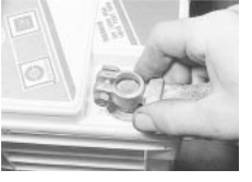
5 A Delco type maintenance-free battery is fitted with a built-in charge condition indicator. The indicator is located in the top of the battery casing, and indicates the condition of the battery from its colour. If the indicator shows green, then the battery is in a good state of charge. If the indicator turns darker, eventually to black, then the battery requires charging, as described later in this Section. If the indicator shows clear/yellow, then the electrolyte level in the battery is too low to allow further use, and the battery should be renewed. Do not attempt to charge, load or jump start a battery when the indicator shows clear/yellow (see illustration .
6 If testing the battery using a voltmeter, connect the voltmeter across the battery and compare the result with those given in the Specifications under "charge condition". The test is only accurate if the battery has not been subjected to any kind of charge for the previous six hours. If this is not the case, switch on the headlights for 30 seconds, then wait four to five minutes before testing the battery after switching off the headlights. All other electrical circuits must be switched off, so check that the doors and tailgate are fully shut when making the test.
7 If the voltage reading is less than 12.2 volts, then the battery is discharged, whilst a reading of to volts indicates a partially discharged condition.

 8 If the battery is to be charged, remove it from the vehicle (Section and charge it as
described later in this Section.
8 If the battery is to be charged, remove it from the vehicle (Section and charge it as
described later in this Section.
Standard and low maintenance battery - charging
Note: The following is intended as a guide only. Always refer to the manufacturer's recommendations (often printed on a label attached to the battery) before charging a battery.
9 Charge the battery at a rate of to 4 amps and continue to charge the battery at this rate until no further rise in specific gravity is noted over a four hour period.
0 Alternatively, a trickle charger charging at the rate of amps can safely be used overnight.
1 Specially rapid `boost' charges which are claimed to restore the power of the battery in
to hours are not recommended, as they can cause serious damage to the battery plates through overheating.
2 While charging the battery, note that the temperature of the electrolyte should never exceed 37.8ºC (100ºF).
Maintenance-free battery - charging
Note: The following is intended as a guide only. Always refer to the manufacturer's recommendations (often printed on a label attached to the battery) before charging a battery.
3 This battery type takes considerably longer to fully recharge than the standard type, the time taken being dependent on the extent of discharge, but it can take anything up to three days.
4 A constant voltage type charger is required, to be set, when connected, to 13.9 to 14.9 volts with a charger current below 25 amps. Using this method, the battery should be usable within three hours, giving a voltage reading of 12.5 volts, but this is for a partially discharged battery and, as mentioned, full charging can take considerably longer.
5 If the battery is to be charged from a fully discharged state (condition reading less than
12.2 volts), have it recharged by your Vauxhall dealer or local automotive electrician, as the charge rate is higher and constant supervision during charging is necessary.
between any cells indicates loss of electrolyte
3.5 Battery condition indicator on maintenance-free type battery
![]() Starting and charging
systems 5A.3
Starting and charging
systems 5A.3
![]()
![]()
![]()
![]()
![]()
![]()
![]()
![]()
![]()
![]()
![]()
![]()
![]()
![]()
![]()
![]() Battery - removal and refitting
Battery - removal and refitting
Removal
1 The battery is located on the left-hand side of the engine bay.
2 Slacken the clamp nut and bolt on the negative (-) terminal clamp (see illustration). Lift the clamp off the terminal post. If the clamp is stuck to the post, beware of using force to free it as the post may be broken. Warm water will usually do the trick.
3 Similarly disconnect the positive terminal;
this may be protected by a plastic cover.
4 Undo the clamp bolt at the base of the battery and lift out the battery. Be careful, it is heavy. Keep it upright and do not drop it. Refitting
5 Refit in the reverse order to removal, connecting the earth (negative) lead last. Use a little proprietary anti-corrosion compound, or petroleum jelly, on the terminal posts. Do not overtighten the clamp bolt or the terminal clamps.
![]()
![]()
![]()
![]()
![]()
![]()
![]()
![]()
![]()
![]()
![]()
![]()
![]()
![]()
![]()
![]()
![]()
![]()
![]()
![]()
![]()
![]()
![]()
![]()
![]()
![]()
![]()
![]()
![]()
![]()
![]()
![]() Charging
system - testing
Charging
system - testing
Note Refer to the warnings given in "Safety first!" and in Section 1 of this Chapter before starting work.
1 If the ignition warning light fails to illuminate when the ignition is switched on, first check the alternator wiring connections for security. If satisfactory, check that the warning light bulb has not blown, and that the bulbholder is secure in its location in the instrument panel. If the light still fails to illuminate, check the continuity of the warning light feed wire from the alternator to the bulbholder. If all is satisfactory, the alternator is at fault and should be renewed or taken to an auto- electrician for testing and repair.
2 If the ignition warning light illuminates when the engine is running, stop the engine and check that the drivebelt is correctly tensioned
(see Chapter and that the alternator connections are secure. If all is so far satisfactory, have the alternator checked by an auto-electrician for testing and repair.
3 If the alternator output is suspect even though the warning light functions correctly, the regulated voltage may be checked as follows.
4 Connect a voltmeter across the battery terminals and start the engine.
5 Increase the engine speed until the voltmeter reading remains steady; the reading should be approximately to volts, and no more than 14 volts.
6 Switch on as many electrical accessories
(eg, the headlights, heated rear window and heater blower) as possible, and check that the alternator maintains the regulated voltage at around 13 to 14 volts.
 4.2 Disconnect the battery negative
terminal first
4.2 Disconnect the battery negative
terminal first
7 If the regulated voltage is not as stated, the fault may be due to worn brushes, weak brush springs, a faulty voltage regulator, a faulty diode, a severed phase winding or worn or damaged slip rings. The alternator should be renewed or taken to an auto-electrician for testing and repair.
![]()
![]()
![]()
![]()
![]()
![]()
![]()
![]()
![]()
![]()
![]()
![]()
![]()
![]()
![]()
![]()
![]()
![]()
![]()
![]()
![]()
![]()
![]()
![]()
![]()
![]()
![]()
![]()
![]()
![]() Alternator
drivebelt - removal, refitting and tensioning
Alternator
drivebelt - removal, refitting and tensioning
Refer to the procedure given for the auxiliary drivebelt(s) in Chapter 1.
![]()
![]()
![]()
![]()
![]()
![]()
![]()
![]()
![]()
![]()
![]()
![]()
![]()
![]()
![]()
![]()
![]()
![]()
![]()
![]()
![]()
![]()
![]()
![]()
![]()
![]()
![]()
![]()
![]()
![]()
![]()
![]() Alternator - removal and refitting
Alternator - removal and refitting
Removal
1 Disconnect the battery earth (negative)
lead.
2 Make a note of the electrical connections at the rear of the alternator, then disconnect the multi-plug, spade terminals or other connectors as appropriate.
3 Remove the alternator strap bolts, noting the short earth lead which links the alternator to the engine. Slacken the pivot bolt, swing the alternator towards the engine and remove the drivebelt.
4 Remove the pivot bolt and lift off the alternator. On one car examined, the pivot bolt had been inserted from the 'wrong' side so that it could not be withdrawn far enough to release the alternator: in this case it is necessary to unbolt the alternator mounting from the block.
5 Take care not to knock or drop the alternator.
Refitting
6 Refit in the reverse order to removal; tension the drivebelt as described in Chapter 1.
![]() Alternator - testing and overhaul
Alternator - testing and overhaul
If the alternator is thought to be suspect, it should be removed from the vehicle and taken to an auto-electrician for testing. Most auto- electricians will be able to supply and fit
brushes at a reasonable cost. However, check on the cost of repairs before proceeding as it may prove more economical to obtain a new or exchange alternator.
![]()
![]()
![]()
![]()
![]()
![]()
![]()
![]()
![]()
![]()
![]()
![]()
![]()
![]()
![]()
![]()
![]()
![]()
![]()
![]()
![]()
![]()
![]()
![]()
![]()
![]()
![]()
![]()
![]()
![]()
![]() Starting
system - testing
Starting
system - testing
Note: Refer to the precautions given in
"Safety first!" and in Section 1 of this Chapter before starting work.
1 If the starter motor fails to operate when the ignition key is turned to the appropriate position, the following possible causes may be to blame.
a) The battery is faulty.
b) The electrical connections between the switch, solenoid, battery and starter motor are somewhere failing to pass the necessary current from the battery through the starter to earth.
c) The solenoid is faulty.
d) The starter motor is mechanically or electrically defective.
![]() 2 To check the battery, switch on the headlights. If they dim after a few seconds,
this indicates that the battery is discharged - recharge (see Section 3) or renew the battery. If the headlights glow brightly, operate the
ignition switch and observe the lights. If they
dim, then this indicates that current is reaching the starter motor, therefore the fault
must lie in the starter motor. If the lights
continue to glow brightly (and no clicking
sound can be heard from the starter motor
solenoid), this indicates that there is a fault in the circuit or solenoid see following
paragraphs. If the starter motor turns slowly
when operated, but the battery is in good
condition, then this indicates that either the
starter motor is faulty, or there is considerable resistance somewhere in the
circuit.
2 To check the battery, switch on the headlights. If they dim after a few seconds,
this indicates that the battery is discharged - recharge (see Section 3) or renew the battery. If the headlights glow brightly, operate the
ignition switch and observe the lights. If they
dim, then this indicates that current is reaching the starter motor, therefore the fault
must lie in the starter motor. If the lights
continue to glow brightly (and no clicking
sound can be heard from the starter motor
solenoid), this indicates that there is a fault in the circuit or solenoid see following
paragraphs. If the starter motor turns slowly
when operated, but the battery is in good
condition, then this indicates that either the
starter motor is faulty, or there is considerable resistance somewhere in the
circuit.
3 If a fault in the circuit is suspected, 5A
disconnect the battery leads (including the earth connection to the body), the starter/solenoid wiring and the engine/transmission earth strap. Thoroughly clean the connections, and reconnect the leads and wiring, then use a voltmeter or test lamp to check that full battery voltage is available at the battery positive lead connection to the solenoid, and that the earth is sound. Smear petroleum jelly around the battery terminals to prevent corrosion - corroded connections are amongst the most frequent causes of electrical system faults.
4 If the battery and all connections are in good condition, check the circuit by disconnecting the wire from the solenoid blade terminal. Connect a voltmeter or test lamp between the wire end and a good earth
(such as the battery negative terminal), and check that the wire is live when the ignition switch is turned to the `start' position. If it is, then the circuit is sound if not the circuit wiring can be checked as described in Chapter 12.
5A.4 Starting and charging systems
5 The solenoid contacts can be checked by connecting a voltmeter or test lamp between the battery positive feed connection on the starter side of the solenoid, and earth. When the ignition switch is turned to the `start' position, there should be a reading or lighted bulb, as applicable. If there is no reading or lighted bulb, the solenoid is faulty and should be renewed.
6 If the circuit and solenoid are proved sound, the fault must lie in the starter motor. In this event, it may be possible to have the starter motor overhauled by a specialist, but check on the cost of spares before proceeding, as it may prove more economical to obtain a new or exchange motor.
![]()
![]()
![]()
![]()
![]()
![]()
![]()
![]()
![]()
![]()
![]()
![]()
![]()
![]()
![]()
![]()
![]()
![]()
![]()
![]()
![]()
![]()
![]()
![]()
![]()
![]()
![]()
![]()
![]()
![]()
![]()
![]() 10 Starter motor - removal and refitting
10 Starter motor - removal and refitting
Removal
1 Disconnect the battery earth lead.
1.2 litre models
2 Disconnect the battery positive leads; separate the starter motor lead from the other. Also disconnect the positive lead from the alternator.
3 Separate the gearshift linkage to improve access. Unbolt and remove the starter motor from above, disconnecting the solenoid command lead.
4 If a new starter motor is being fitted, transfer the electrical lead to it.
1.4, 1.6, 1.8 and 2.0 litre 8-valve models
5 Raise and support the front of the vehicle
(see "Jacking and Vehicle Support").
6 Note the electrical connections to the starter solenoid, then disconnect them.
7 Unbolt the starter motor and remove it from below (see illustration .
2.0 litre 16-valve models
8 Remove the starter motor-to-transmission bolts which are accessible from above.
9 Raise and support the front of the vehicle
(see Jacking and Vehicle Support"). Remove the inlet manifold bracing strap.
0 Disconnect the main feed and command leads from the starter motor.
1 Remove the remaining starter motor mounting bolts, not forgetting the bracket at the brushgear end of the motor. Remove the motor from below.
Refitting
2 Refitting is the reverse of the removal procedure.
![]() 11 Starter motor - testing and overhaul
11 Starter motor - testing and overhaul
If the starter motor is thought to be suspect, it should be removed from the vehicle and taken to an auto-electrician for testing. Most auto-electricians will be able to supply and fit brushes at a reasonable cost. However, check on the cost of repairs before proceeding as it may prove more economical to obtain a new or exchange motor.
![]()
![]()
![]()
![]()
![]()
![]()
![]()
![]()
![]()
![]()
![]()
![]()
![]()
![]()
![]()
![]()
![]()
![]()
![]()
![]()
![]()
![]()
![]()
![]()
![]()
![]() 12 Ignition switch - removal and refitting
12 Ignition switch - removal and refitting
Refer to Chapter 10.
![]()
![]()
![]()
![]()
![]()
![]()
![]()
![]()
![]()
![]()
![]()
![]()
![]()
![]()
![]()
![]()
![]()
![]()
![]()
![]()
![]()
![]()
![]()
![]()
![]()
![]()
![]()
![]()
![]()
![]()
![]()
![]()
 13 Oil pressure warning light switch/gauge
sender - removal and refitting
13 Oil pressure warning light switch/gauge
sender - removal and refitting
Removal
1 The switch/gauge sender is screwed into the cylinder block or oil filter carrier
(depending on model).
![]() 2 Disconnect the battery negative lead and disconnect the wiring from the switch/sender
2 Disconnect the battery negative lead and disconnect the wiring from the switch/sender
(see illustration
3 Unscrew the switch/sender and recover the sealing washer. Be prepared for oil spillage, and if the switch is to be left removed from the engine for any length of time, plug the hole. Refitting
4 Examine the sealing washer for signs of damage or deterioration and if necessary renew.
5 Refit the switch/sender, complete with washer, and tighten it securely. Reconnect the wiring.
6 Check and, if necessary, top-up the engine oil as described in Chapter 1.
![]()
![]()
![]()
![]()
![]()
![]()
![]()
![]()
![]()
![]()
![]()
![]()
![]()
![]()
![]()
![]()
![]()
![]()
![]()
![]()
![]()
![]()
![]()
![]()
![]()
![]()
![]()
![]()
![]()
![]()
![]() 14 Oil level sensor (16-valve models) - removal and refitting
14 Oil level sensor (16-valve models) - removal and refitting
Removal
1 Raise and support the front of the vehicle
(see "Jacking and Vehicle Support").
2 Disconnect the battery earth (negative)
lead.
3 Drain the engine oil, saving it if it is fit for re-use.
4 Follow the sensor wiring back to its connection with the main wiring harness and disconnect it. (Early type sensors have a wiring plug secured with two screws, which can be disconnected at the sensor.)
5 Remove the four screws which secure the sensor to the sump. Remove the sensor and recover the seal.
Refitting
6 Refitting is the reverse of the removal procedure. Use a new seal. Refill the engine with oil on completion.
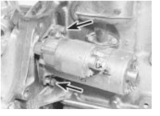
 10.7 Starter motor mounting bolts
(arrowed) - engine removed for clarity
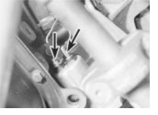
 13.2 Oil pressure sender wires
(arrowed)
13.2 Oil pressure sender wires
(arrowed)
|
