ALTE DOCUMENTE
|
||||||||
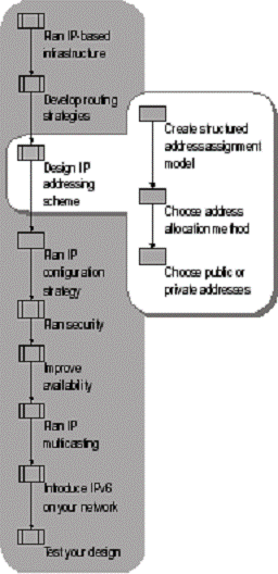
Before assigning addresses, design an IP addressing scheme that meets the requirements of your networking infrastructure. Figure 1.5 shows the tasks involved in designing your IP addressing system, including planning your address assignment model, address allocation, and public or private addressing. Most organizations choose to use classless IP addressing, classless IP routing protocols, and route summarization.
Figure 1.5 Designing an IP Addressing Scheme
For information about IP multicast addressing, see Planning IP Multicasting" later in this chapter.
You can ease the burden of enterprise internetwork administration by designing a structured address assignment model. A structured address assignment model makes troubleshooting easier and more systematic and helps you interpret network maps and locate specific devices. It also simplifies the use of network management software. For enterprise scalability, assign address blocks hierarchically.
The structured address assignment model reflects more than jus 17117p1515r t hierarchical concerns. To maximize network stability and scalability, assign a block of addresses based on a physical network rather than on membership within a department or team, to avoid complications when you move a workstation to a new location. For more information about address allocation as it relates to your IP addressing scheme, see "Choosing an Address Allocation Method" later in this chapter.
As a general rule, assign static addresses to routers and servers, and assign dynamic addresses to workstations. This scheme minimizes manual addressing, reducing the chances of address duplication and stabilizing the network's addressing structure. You can assign meaningful numbers when using static addresses; for example, reserve host addresses in the low or high portion of the range, and manually assign these addresses to routers or servers.
To design a structured model for assigning addresses:
Plan classless IP addressing.
Plan classless routing.
Use route summarization.
Plan variable length subnet masks (VLSM).
Plan supernetting and classless interdomain routing (CIDR).
Classless IP addressing makes traditional classful IP addressing methods - restricted to the standard IP address classes in their default formats - out of date for enterprise networks. Of the five address classes, Class A, B, and C addresses, collectively known as IPv4 unicast addresses, are assigned to specific devices on an IPv4 network. Class D addresses, known as multicast addresses, are used for IP multicasting (simultaneously sending a message to more than one network destination). Class E addresses are reserved for experimental purposes.
To be able to use subnetting or supernetting, you must first understand the default formats of the unicast addresses. Unicast addresses have the following formats:
All 32-bit IPv4 addresses contain four octets of 8 bits each, often represented as four decimal numbers separated by dots (known as dotted decimal notation).
In Class A addresses, the first byte, or octet, represents the network ID, and the three remaining bytes are used for node addresses.
In Class B addresses, the first 2 bytes represent the network ID, and the last 2 bytes are used for nodes.
In Class C addresses, the first 3 bytes are used for the network ID, and the final byte is used for nodes.
Without some means of subdividing class-designated networks, all available IP addresses would have been depleted long ago. Classless IP addressing, which allows subnetting, was developed to handle this problem.
To better use the address space, instead of using the unicast addresses in their default formats, you can use subnet addressing, which lets you "borrow" additional bits from the host part of the address to divide the network into subnets. In subnetting, the subnet mask consists of the octets assigned to the network plus the bits added for the subnet. You can use subnet mask notation to indicate these leftmost contiguous bits.
For example, for a Class B address, which has a default subnet mask of 255.255.0.0, you might allocate an additional 8 bits for subnets. That is, for a Class B address such as 131.107.65.37, you can use the following subnet mask, shown in both decimal and binary notation.
|
Subnet Mask in Decimal Notation |
Subnet Mask in Binary Notation |
By using 8 host bits for subnetting, you obtain 256 (that is, 2 ) subnetted network IDs (subnets), supporting as many as 254 hosts per subnet. The number of hosts per subnet is 254 because 8 bits (2 minus 2) are reserved for the host ID. You subtract 2 because subnetting rules exclude the host IDs consisting of all ones or all zeros.
An alternative to subnet mask notation is the network prefix length notation. A network prefix is shorthand for a subnet mask, expressing the number of high-order bits that constitute the subnetted network ID portion of the address in the format <IP address>/<# of bits>, where # of bits defines the network/subnet part of the IP address, and the remaining bits represent the host ID portion of the address.
The following is the network prefix length notation for the Class B address in the previous example:
131.107.65.37/24
The bit notation "/24" refers to the number of high-order bits set to 1 in the binary notation for the subnet mask, leaving 8 bits for hosts (the eight bits set to 0).
|
|
|
Note IPv6 supports only network prefix length notation. It does not support dotted decimal subnet masks. For more information about IPv6, see "Introducing IPv6 on Your Network" later in this chapter. |
By contrast, if you anticipate needing only 32 subnets rather than 256, each of the 32 subnets can support as many as 2,046 hosts (2 minus 2). That subnet mask has the following decimal and binary notations.
|
Subnet Mask in Decimal Notation |
Subnet Mask in Binary Notation |
The following network prefix length notation indicates the 21 bits needed to create as many as 32 subnets:
131.107.65.37/21.
Again, "/21" indicates the number of high-order bits set to 1 in binary notation, leaving 11 bits (the 11 zeros) for the host ID portion of the address.
To determine the appropriate number of subnets versus hosts for your organization's network, consider the following:
More subnets. Allocating more host bits for subnetting supports more subnets but fewer hosts per subnet.
More hosts. Allocating fewer host bits for subnetting supports more hosts per subnet, but limits the growth in the number of subnets.
For an introduction to TCP/IP, including information about subnetting, see the Networking Guide of the Windows Server 2003 Resource Kit (or see the Networking Guide on the Web at https://www.microsoft.com/reskit).
Organizations today typically implement classless routing solutions. With classful routing protocols, IP hosts and routers recognize only the network address designated by the standard address classes. An IP host device or a router using a classful protocol such as RIP v1 cannot recognize subnets.
Classless routing protocols extend the standard Class A, B, or C IP addressing scheme by using a subnet mask or mask length to indicate how routers must interpret an IP network ID. Classless routing protocols include the subnet mask along with the IP address when advertising routing information. Subnet masks representing the network ID are not restricted to those defined by the address classes, but can contain a variable number of high-order bits. Such subnet mask flexibility enables you to group several networks as a single entry in a routing table, significantly reducing routing overhead. In addition to RIP v2 and OSPF, described earlier, classless routing protocols include Border Gateway Protocol version 4 (BGP4) and Intermediate System to Intermediate System (IS-IS).
If your network contains routers that support only RIP v1 and you want to upgrade from classful to classless routing, upgrade the RIP v1 routers to support RIP v2 or use another protocol such as OSPF. For example, you might use VLSM to implement subnets of different sizes or CIDR to implement supernetting. (VLSM and CIDR are described later in this chapter.)
One reason that classful routing is out of date is that classful routing protocols cannot reliably handle noncontiguous subnets of a subnetted class-based network ID. As mentioned earlier, classful routing protocols recognize only those networks indicated by an address class. Because classful protocols do not transmit subnet mask or prefix length information, noncontiguous subnets, when summarized by a classful routing protocol, can have the same class-based network ID.
Noncontiguous subnets occur when another network with a different network ID separates subnets of a classful network. For example, the two routers in Figure 1.6 separate two subnets that each use the base prefix 10.0.0.0/8, which is a Class A private network. A segment of another class-based network connects the two routers. (For more information about private addresses, see "Choosing Public or Private Addresses" later in this chapter.)
Figure 1. Classful Routing Not Appropriate for Noncontiguous Subnets
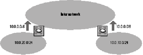
Each router in Figure 1.6 must use a subnet mask to look up a match in the routing table. Because a classful address, by definition, has only its class-based default subnet mask, the router uses the network mask that corresponds to the class of the subnet ID when advertising the route for the subnet. With classful routing, each of the routers in Figure 1.6 summarizes and advertises the class-based network ID of 10.0.0.0/8, resulting in two routes to 10.0.0.0/8, each of which might have a different metric. Therefore, a packet meant for one subnet could be incorrectly routed to the other subnet. In the figure, the arrows represent the routes advertised by the routers.
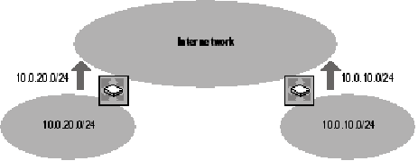
Figure 1.7 also shows an unrelated network connecting two noncontiguous subnets. In this example, using classless routing, the locations on the noncontiguous subnets are unambiguous because the classless protocol includes a subnet mask when advertising the route. Routers in the intermediate network can distinguish between the two noncontiguous subnets.
Figure 1. Classless Routing Appropriate for Noncontiguous Subnets
With route summarization, or aggregation, in a hierarchical routing infrastructure, one route in a routing table represents many routes. A routing table entry for the highest level (the network) is also the route used for subnets and sub-subnets. In contrast, in a flat routing infrastructure, the routing table on every router in the network contains an entry for each network segment. When you use flat routing, the network IDs have no network/subnet structure and cannot be summarized. RIP-based Internet Packet Exchange (IPX) internetworks use flat network addressing and have a flat routing infrastructure.
Using route summarization, you can contain topology changes occurring in one area of the network within that area. Route summarization simplifies routing tables and reduces the exchange of routing information, but it requires more planning than does a flat routing infrastructure.
To support route summarization, your IP addressing scheme must meet the following requirements:
Classless routing protocols (those including subnet mask or prefix length information along with the IP address) must be used.
All IP addresses used in route summarization must share identical high-order bits.
The length of the prefix can be any number of bits up to 32 (for IPv4).
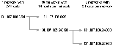
Variable length subnet masks (VLSMs) allow you to use different prefix lengths at different locations so that subnets of different sizes can coexist on the same network. Instead of using one subnet mask throughout the network, you apply several masks to the same address space, producing subnets of different sizes. For example, given the Class B network ID of 131.107.0.0, you can configure one subnet with as many as 32,766 hosts, 15 subnets with as many as 2,046 hosts, and 8 subnets with as many as 254 hosts.
|
|
|
Tip When using VLSM, do not accidentally overlap blocks of addresses. If possible, start with equal-size subnets and then subdivide them. |
VLSM also can be used when a point-to-point WAN link connects two routers. One way to handle such a WAN link is to create a small subnet consisting of only two addresses. Without VLSM, you might divide a Class C network ID into an equal number of two-address subnets. If only one WAN link is in use, all the subnets but one serve no purpose, wasting 252 addresses.
Alternatively, you can divide the Class C network into 16 workgroup subnets of 14 nodes each by using a prefix length of 28 bits (or, in subnet mask terms, 255.255.255.240). By using VLSM, you can then subdivide one of those 16 subnets into 8 smaller subnets, each supporting only 2 nodes. You can use one of the 8 subnets for your existing WAN link and reserve the remaining 7 subnets for similar links that you might need in the future. To accomplish this act of sub-subnetting by using VLSM, use a prefix length of 30 bits (or, in subnet mask terms, 255.255.255.252).
Figure 1.8 shows variable length subnetting for two-host WAN subnets.
Figure 1. Variable Length Subnetting of 131.107.106.0
If your network includes numerous WAN links, each with its own subnet, this approach can require significant administrative overhead. If you do not use route summarization, each subnet requires another entry in the routing table, increasing the overhead of the routing process.
Some routers support unnumbered connections; a link with unnumbered connections does not require its own subnet.
Similar to the way that subnetting allows you to divide class-based networks into smaller subnets by "borrowing" bits from the host part of the address, supernetting allows you to combine contiguous subnets into larger supernets by "borrowing" bits from the network part of the address. For example, rather than allocate a Class B network ID to an organization that has 2,000 hosts, the Internet Assigned Numbers Authority (IANA) might allocate a range of eight Class C network IDs. Each Class C network ID accommodates 254 hosts, for a total of 2,032 host IDs.
Although this technique helps conserve Class B network IDs, it creates a new problem. Using conventional routing techniques, the routers on the Internet must, in this example, have eight Class C network ID entries in their routing tables to route IP packets to the organization. To prevent Internet routers from becoming overwhelmed with routes, a technique called Classless Interdomain Routing (CIDR), which the Internet uses to summarize routes, collapses multiple network ID entries into a single entry. In this example, CIDR collapses the network IDs that correspond to the eight Class C network IDs allocated to that organization into one entry.
A supernetted subnet mask conveys the starting network ID and the number of Class C network IDs allocated. The following tables demonstrate how eight Class C network IDs are allocated. Table 1.1 indicates the contiguous allocation of eight Class C network IDs, starting with network ID 220.78.168.0. Note that the first 21 bits (underlined) are the same for the starting network ID and the ending network ID. The last 3 bits of the third octet, which are borrowed from the network ID, range from 000 through 111. In decimal notation, the range is 0 through 7, or 8 total contiguous subnets, which are combined into one supernet.
Table 1. Supernetted Block of Addresses
|
Network ID |
Subnet Mask (Binary) |
|
|
Starting Network ID | ||
|
Ending Network ID |
A block of supernetted addresses, such as those in Table 1.2, is known as a CIDR block. Table 1.2 indicates the single CIDR entry that appears in the routing table. This entry represents all eight Class C network IDs that are allocated to the example organization.
Table 1. CIDR Routing Table Entry
|
Network ID |
Subnet Mask |
Subnet Mask (Binary) |
In network prefix length notation, the CIDR block is 220.78.168.0/21.
RIP v2, OSPF, and BGP4, which can exchange routing information in the form of [Network ID, Network Mask] pairs, support CIDR.
|
