ALTE DOCUMENTE
|
||||||||||
Adding a digital output to your Xbox (v0.1)
Tutorial written by : DataBitz
The following is what I have found from the forums and other documents floating around the web. I do not take any credit for figuring it out, I didn't. I have tried the coax mod myself on a PAL v1.1 Xbox and it works sweet. If you try it then you will void your warranty. I take no responsibility for any damage caused by attempting this modification, hack at your own risk.
Introduction:
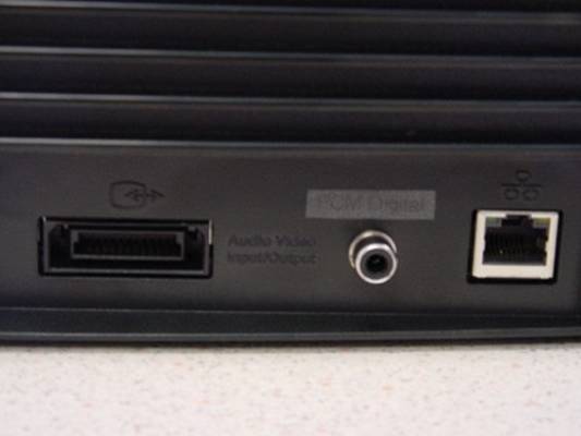
For reference, the pi 454h77e ns we use are as follows:
Pin 3 = Digital SP-DIF signal
Pin 5 = Mode ground
Pin 13 = 5 volt supply (required for optical connector only)
Pin 18 = Mode 2 (when grounded tells the Xbox that an AV connector with digital
output is connected, enabling the option in the menu for Dolby Digital)
Option 1. Coax (RCA)

click image for full view
Parts required: - RCA socket (one that is designed to
mount to a panel, not into a PCB or onto a loose wire)
- Some thin insulated wires, solder and a low wattage soldering iron with a
fine tip, a torx screwdriver
Instructions:
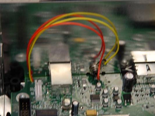
1. Open the Xbox (voiding your warranty)
2. Remove all the drives and remove the mainboard. Flip it over and locate the
AV connector (as pictured)
3. Solder a wire from Pin 5 on the AV connector to the outside (ground) leg of
the RCA socket. *
4. Solder another wire from Pin 3 of the AV connector to the center (data) leg
of a RCA connector. *
5. Solder another wire from Pin 18 of the AV connector to a grounded point on
the board.
6. Find somewhere you would like the socket to stick out the case (make sure
there's still room for it there when the case is put back together), and drill
a hole and mount it there (depending on the RCA socket it could mount in one of
various ways, you will need to work this out for yourself)
* There is a hole in the mainboard located next to the LAN connector, it is right next to where the '8' co-ordinate is printed. This hole is big enough to fit the 2 wires through so the RCA socket can be above the mainboard when reassembled.
This is what it looked like when completed.
Option 2. Optical (TosLink) - untested

click image for full view
Parts required: - Toslink Optical transmitter TOTX173 or
TOTX176 or TOTX178a
- 100nF capacitor
- Some thin insulated wires, solder and a low wattage soldering iron with a
fine tip, a torx screwdriver
Instructions: 1. Open the Xbox (voiding your warranty)
2. Remove all the drives and remove the mainboard. Flip it over and locate the
AV connector (as pictured)
3. Solder a wire from Pin 3 of the AV connector to the data leg of the TosLink
connector. *
4. Solder another wire from Pin 5 of the AV connector to the ground leg of the
TosLink connector. *
5. Solder another wire from Pin 13 of the AV connector to the Vcc leg of the
TosLink connector. *
6. Link a 100nF capacitor between the Vcc and Ground legs of the TosLink
connector.
7. Solder another wire from Pin 18 of the AV connector to a grounded point on
the board.
8. Find somewhere you would like the socket to stick out the case (make sure
there's still room for it there when the case is put back together), and drill
a hole and mount it there (depending on the TosLink socket it could mount in
one of various ways, you will need to work this out for yourself)
* There is a hole in the mainboard located near the LAN connector, it is right next to where the '8' co-ordinate is printed. This hole is big enough to fit the power wires through so the optical connector can be above the mainboard when reassembled, the 3rd (data) wire will fit through another smaller hole located between the AV connector and the LAN connector, just above the pin 3 hole of unused J6A1, if you cant squeeze 3 wires through the other larger hole.
Tutorial written by : DataBitz
|
