![]() DOHC (16-valve) engine
DOHC (16-valve) engine
Contents
Ancillary components - removal and refitting . . . . . . . . . . . . . . . . . . . .5
Camshaft sprocket oil seals - renewal . . . . . . . . . . . . . . . . . . . . . . . . .9
Camshaft toothed belt - removal and refitting . . . . . . . . . . . . . . . . . . .7
Camshaft toothed belt tensioner and idler rollers - removal and
refitting . . . . . . . . . . . . . . . . . . . . . . . . . . . . . . . . . . . . . . . . . . . . . . .8
Camshafts - removal and refitting . . . . . . . . . . . . . . . . . . . . . . . . . . .10
Compression test - description and interpretation . . . . . . . . . . . . . . . .2
Crankshaft and main bearings - removal and refitting . . . . . . . . . . . .23
Crankshaft front oil seal - renewal . . . . . . . . . . . . . . . . . . . . . . . . . . .17
Crankshaft rear oil seal - renewal . . . . . . . . . . . . . . . . . . . . . . . . . . . .21
Cylinder head - overhaul . . . . . . . . . . . . . . . . . . . . . . . . . . . . . . . . . .12
Cylinder head - removal and refitting . . . . . . . . . . . . . . . . . . . . . . . . .11
Engine oil and filter - renewal . . . . . . . . . . . . . . . . . . . . .See Chapter 1
Engine oil level check . . . . . . . . . . . . . . . . . . . . . . .See Weekly checks
Engine - initial start-up after overhaul . . . . . . . . . . . . . . . . . . . . . . . .26
Engine - removal and refitting . . . . . . . . . . . . . . . . . . . . . . . . . . . . . .25
Engine components - examination and renovation . . . . . . . . . . . . . .24
Engine dismantling and reassembly - general . . . . . . . . . . . . . . . . . . .4
Engine/transmission mountings - removal and refitting . . . . . . . . . . .22
Flywheel - removal and refitting . . . . . . . . . . . . . . . . . . . . . . . . . . . . .20
General description . . . . . . . . . . . . . . . . . . . . . . . . . . . . . . . . . . . . . . .1
General engine checks . . . . . . . . . . . . . . . . . . . . . . . . . .See Chapter 1
Oil cooler thermostatic - valve removal and refitting . . . . . . . . . . . . .16
Oil pressure regulating valve - removal and refitting . . . . . . . . . . . . . .6
Oil pump - overhaul . . . . . . . . . . . . . . . . . . . . . . . . . . . . . . . . . . . . . .15
Oil pump - removal and refitting . . . . . . . . . . . . . . . . . . . . . . . . . . . . .14
Operations requiring engine removal . . . . . . . . . . . . . . . . . . . . . . . . . .3
Pistons and connecting rods - dismantling and reassembly . . . . . . .19
Pistons and connecting rods - removal and refitting . . . . . . . . . . . . .18
Sump and oil baffle plate - removal and refitting . . . . . . . . . . . . . . . .13
Degrees of difficulty
![]() 2C
2C

![]()
![]()
![]()
![]()
![]()
![]()
![]()
![]()
![]()
![]()
![]()
![]()
![]()
![]()
![]()
![]()
![]()
![]()
![]()
![]()
![]()
![]()
![]()
![]()
![]()
![]()
![]()
![]()
![]()
![]()
![]()
![]()
![]()
![]()
![]()
![]()
![]()
![]()
![]()
![]()
![]()
![]()
![]()
![]()
![]()
![]()
![]()
![]()
![]()
![]()
![]()
![]()
![]()
![]()
![]()
![]()
![]()
![]()
![]()
![]()
![]()
![]()
![]()
![]()
![]()
![]()
![]()
![]()
![]()
![]()
![]()
![]()
![]()
![]()
![]()
![]()
![]()
![]()
![]()
![]()
![]()
![]()
![]()
![]()
![]()
![]()
![]()
![]()
![]()
![]()
![]()
![]()
![]()
![]()
![]()
![]()
![]()
![]()
![]()
![]()
![]()
![]()
![]()
![]()
![]()
![]()
![]()
![]()
![]()
![]()
![]()
![]()
![]()
![]()
![]()
![]()
![]()
![]()
![]()
![]()
![]()
![]()
![]()
![]()
![]()
![]()
![]()
![]()
![]()
![]()
![]()
![]()
![]()
![]()
![]()
![]()
![]() Easy suitable for novice with little experience
Easy suitable for novice with little experience
Fairly easy suitable for beginner with some experience
Fairly difficult, suitable for competent DIY mechanic
Difficult suitable for experienced DIY mechanic
Very difficult, suitable for expert DIY or professional
Specifications
General
Type . . . . . . . . . . . . . . . . . . . . . . . . . . . . . . . . . . . . . . . . . . . . . . . . . . . . Four-cylinder, in-line, water-cooled, double overhead camshaft, transversely mounted
Engine code* . . . . . . . . . . . . . . . . . . . . . . . . . . . . . . . . . . . . . . . . . . . . . . 20XE, C20XE* or 20XEJ Bore . . . . . . . . . . . . . . . . . . . . . . . . . . . . . . . . . . . . . . . . . . . . . . . . . . . . 86.0 mm
Stroke . . . . . . . . . . . . . . . . . . . . . . . . . . . . . . . . . . . . . . . . . . . . . . . . . . . 86.0 mm
Capacity . . . . . . . . . . . . . . . . . . . . . . . . . . . . . . . . . . . . . . . . . . . . . . . . . 1998 cc
Firing order . . . . . . . . . . . . . . . . . . . . . . . . . . . . . . . . . . . . . . . . . . . . . . . 1-3-4-2 (No 1 cylinder at crankshaft pulley end) Direction of crankshaft rotation . . . . . . . . . . . . . . . . . . . . . . . . . . . . . . . Clockwise
Compression ratio . . . . . . . . . . . . . . . . . . . . . . . . . . . . . . . . . . . . . . . . . 10.5: 1
Note: The engine code forms the first digits of the engine number
Cylinder block
Cylinder bore diameter: Diameter Marking
Standard size 1 . . . . . . . . . . . . . . . . . . . . . . . . . . . . . . . . . . . . . . . . . . . . 85.98 mm 8
85.99 mm 99
86.00 mm 00
86.01 mm 01
Standard size 2 . . . . . . . . . . . . . . . . . . . . . . . . . . . . . . . . . . . . . . . . . . . . 86.02 mm 02
Oversize (0.5 mm) . . . . . . . . . . . . . . . . . . . . . . . . . . . . . . . . . . . . . . . . . . 86.47 mm 7 + 0.5
86.48 mm 8 + 0.5
86.49 mm 9 + 0.5
86.50 mm 0 + 0.5
Maximum cylinder bore ovality . . . . . . . . . . . . . . . . . . . . . . . . . . . . . . . . 0.013 mm
Maximum cylinder bore taper . . . . . . . . . . . . . . . . . . . . . . . . . . . . . . . . . 0.013 mm
![]() 2C.2 DOHC
(16-valve) engine
2C.2 DOHC
(16-valve) engine
Crankshaft
Number of main bearings . . . . . . . . . . . . . . . . . . . . . . . . . . . . . . . . . . . . 5
Main bearing journal diameter . . . . . . . . . . . . . . . . . . . . . . . . . . . . . . . . 57.982 to 57.995 mm Crankpin diameter . . . . . . . . . . . . . . . . . . . . . . . . . . . . . . . . . . . . . . . . . 48.971 to 48.987 mm Undersizes . . . . . . . . . . . . . . . . . . . . . . . . . . . . . . . . . . . . . . . . . . . . . . . 0.25 and 0.50 mm Crankshaft endfloat . . . . . . . . . . . . . . . . . . . . . . . . . . . . . . . . . . . . . . . . 0.07 to 0.3 mm
Main bearing running clearance . . . . . . . . . . . . . . . . . . . . . . . . . . . . . . . 0.015 to 0.04 mm Big-end running clearance . . . . . . . . . . . . . . . . . . . . . . . . . . . . . . . . . . . 0.019 to 0.063 mm Big-end side-play . . . . . . . . . . . . . . . . . . . . . . . . . . . . . . . . . . . . . . . . . . 0.07 to 0.24 mm Bearing shell identification:
Top shells:
Main bearings, standard . . . . . . . . . . . . . . . . . . . . . . . . . . . . . . . . . Brown
Main bearings, 0.25 mm undersize . . . . . . . . . . . . . . . . . . . . . . . . . Brown/blue Main bearings, 0.5 mm undersize . . . . . . . . . . . . . . . . . . . . . . . . . . Brown/white Big-end bearings, standard . . . . . . . . . . . . . . . . . . . . . . . . . . . . . . None
Big-end bearings, 0.25 mm undersize . . . . . . . . . . . . . . . . . . . . . . Blue
Big-end bearings, 0.5 mm undersize . . . . . . . . . . . . . . . . . . . . . . . White
Bottom shells:
Main bearings, standard . . . . . . . . . . . . . . . . . . . . . . . . . . . . . . . . . Green
Main bearings, 0.25 mm undersize . . . . . . . . . . . . . . . . . . . . . . . . . Green/blue Main bearings, 0.5 mm undersize . . . . . . . . . . . . . . . . . . . . . . . . . . Green/white Big-end bearings, standard . . . . . . . . . . . . . . . . . . . . . . . . . . . . . . None
Big-end bearings, 0.25 mm undersize . . . . . . . . . . . . . . . . . . . . . . Blue
Big-end bearings, 0.5 mm undersize . . . . . . . . . . . . . . . . . . . . . . . White
Main and big-end bearing journal out-of-round . . . . . . . . . . . . . . . . . . . 0.04 mm max Crankshaft radial run-out (at centre journal, shaft in block) . . . . . . . . . . 0.03 mm max Pistons and piston rings
Piston diameter . . . . . . . . . . . . . . . . . . . . . . . . . . . . . . . . . . . . . . . . . . . . 0.03 mm less than bore diameter
Piston-to-bore clearance . . . . . . . . . . . . . . . . . . . . . . . . . . . . . . . . . . . . 0.02 to 0.04 mm
Gudgeon pins
Length . . . . . . . . . . . . . . . . . . . . . . . . . . . . . . . . . . . . . . . . . . . . . . . . . . . 61.5 mm
Diameter . . . . . . . . . . . . . . . . . . . . . . . . . . . . . . . . . . . . . . . . . . . . . . . . . 21 mm
Clearance in piston . . . . . . . . . . . . . . . . . . . . . . . . . . . . . . . . . . . . . . . . . 0.003 to 0.010 mm Clearance in connecting rod . . . . . . . . . . . . . . . . . . . . . . . . . . . . . . . . . . 0.015 to 0.030 mm Cylinder head
Minimum acceptable height after machining . . . . . . . . . . . . . . . . . . . . . 135.63 mm
Maximum acceptable gasket face distortion . . . . . . . . . . . . . . . . . . . . . 0.025 mm
Camshaft bearing bore diameter . . . . . . . . . . . . . . . . . . . . . . . . . . . . . . 28.000 to 28.021 mm
Valve seat width:
Inlet . . . . . . . . . . . . . . . . . . . . . . . . . . . . . . . . . . . . . . . . . . . . . . . . . . . 1.0 to 1.4 mm Exhaust . . . . . . . . . . . . . . . . . . . . . . . . . . . . . . . . . . . . . . . . . . . . . . . . 1.4 to 1.8 mm Camshafts
Drive . . . . . . . . . . . . . . . . . . . . . . . . . . . . . . . . . . . . . . . . . . . . . . . . . . . . Toothed belt
Number of bearings:
Inlet . . . . . . . . . . . . . . . . . . . . . . . . . . . . . . . . . . . . . . . . . . . . . . . . . . . 5
Exhaust . . . . . . . . . . . . . . . . . . . . . . . . . . . . . . . . . . . . . . . . . . . . . . . . 6
Bearing journal diameter . . . . . . . . . . . . . . . . . . . . . . . . . . . . . . . . . . . . . 27.939 to 27.960 mm
Bearing journal running clearance . . . . . . . . . . . . . . . . . . . . . . . . . . . . . 0.061 mm Camshaft endfloat . . . . . . . . . . . . . . . . . . . . . . . . . . . . . . . . . . . . . . . . . 0.04 to 0.144 mm Cam lift . . . . . . . . . . . . . . . . . . . . . . . . . . . . . . . . . . . . . . . . . . . . . . . . . . 9.5 mm
Valves
Operation . . . . . . . . . . . . . . . . . . . . . . . . . . . . . . . . . . . . . . . . . . . . . . . . Bucket tappet incorporating hydraulic adjuster
Seat angle . . . . . . . . . . . . . . . . . . . . . . . . . . . . . . . . . . . . . . . . . . . . . . . . ° 40' Length:
Production . . . . . . . . . . . . . . . . . . . . . . . . . . . . . . . . . . . . . . . . . . . . . 105 mm
Service . . . . . . . . . . . . . . . . . . . . . . . . . . . . . . . . . . . . . . . . . . . . . . . . 104.6 mm
Head diameter:
Inlet . . . . . . . . . . . . . . . . . . . . . . . . . . . . . . . . . . . . . . . . . . . . . . . . . . . 33 mm
Exhaust . . . . . . . . . . . . . . . . . . . . . . . . . . . . . . . . . . . . . . . . . . . . . . . . 29 mm
Stem diameter (standard):
Inlet . . . . . . . . . . . . . . . . . . . . . . . . . . . . . . . . . . . . . . . . . . . . . . . . . . . 6.955 to 6.970 mm Exhaust . . . . . . . . . . . . . . . . . . . . . . . . . . . . . . . . . . . . . . . . . . . . . . . . 6.945 to 6.960 mm Stem diameter (oversize) . . . . . . . . . . . . . . . . . . . . . . . . . . . . . . . . . . . . 0.075 and 0.150 mm
Stem-to-guide clearance:
Inlet . . . . . . . . . . . . . . . . . . . . . . . . . . . . . . . . . . . . . . . . . . . . . . . . . . . 0.045 mm
Exhaust . . . . . . . . . . . . . . . . . . . . . . . . . . . . . . . . . . . . . . . . . . . . . . . . 0.055 mm
Valve clearance . . . . . . . . . . . . . . . . . . . . . . . . . . . . . . . . . . . . . . . . . . . . Automatic adjustment by hydraulic adjusters
DOHC (16-valve) engine 2C.3
![]() Valves (continued)
Valves (continued)
Valve guide internal diameter:
Standard . . . . . . . . . . . . . . . . . . . . . . . . . . . . . . . . . . . . . . . . . . . . . . . 7.000 to 7.015 mm Oversizes . . . . . . . . . . . . . . . . . . . . . . . . . . . . . . . . . . . . . . . . . . . . . . 0.075 and 0.150 mm Valve guide installed height . . . . . . . . . . . . . . . . . . . . . . . . . . . . . . . . . . 10.70 to 11.00 mm
Torque wrench settings Nm lbf ft
Starter motor-to-block bolts . . . . . . . . . . . . . . . . . . . . . . . . . . . . . . . . . . 5
Starter motor bracket-to-block bolts . . . . . . . . . . . . . . . . . . . . . . . . . . . 5
Manifold nuts . . . . . . . . . . . . . . . . . . . . . . . . . . . . . . . . . . . . . . . . . . . . . 0
Alternator mounting-to-block bolts . . . . . . . . . . . . . . . . . . . . . . . . . . . . 0
Steering pump mounting-to-block bolts . . . . . . . . . . . . . . . . . . . . . . . . 0
Crankshaft pulley-to-sprocket screws with splined heads . . . . . . . . . . 0
Crankshaft sprocket central bolt (greased threads):
Stage 1 . . . . . . . . . . . . . . . . . . . . . . . . . . . . . . . . . . . . . . . . . . . . . . . . 250 184
Stage 2 . . . . . . . . . . . . . . . . . . . . . . . . . . . . . . . . . . . . . . . . . . . . . . . . Angle-tighten a further 40 to 5 ° Main bearing caps:
Stage 1 . . . . . . . . . . . . . . . . . . . . . . . . . . . . . . . . . . . . . . . . . . . . . . . . 0
Stage 2 . . . . . . . . . . . . . . . . . . . . . . . . . . . . . . . . . . . . . . . . . . . . . . . . Angle-tighten a further 4 ° to 50° Big-end bearing caps:
Stage 1 . . . . . . . . . . . . . . . . . . . . . . . . . . . . . . . . . . . . . . . . . . . . . . . . 5
Stage 2 . . . . . . . . . . . . . . . . . . . . . . . . . . . . . . . . . . . . . . . . . . . . . . . . Angle-tighten a further 4 ° to 60° Engine mountings (use thread-locking compound) . . . . . . . . . . . . . . . . 5
Camshaft bearing caps:
M8 nuts . . . . . . . . . . . . . . . . . . . . . . . . . . . . . . . . . . . . . . . . . . . . . . . . 0
M6 nuts . . . . . . . . . . . . . . . . . . . . . . . . . . . . . . . . . . . . . . . . . . . . . . . . 0
Oil drain plug . . . . . . . . . . . . . . . . . . . . . . . . . . . . . . . . . . . . . . . . . . . . . 5
Oil pump housing-to-block bolts . . . . . . . . . . . . . . . . . . . . . . . . . . . . . . 6 4
Sump bolts (use thread-locking compound) . . . . . . . . . . . . . . . . . . . . . 5
Flywheel bolts (use thread-locking compound):
Stage 1 . . . . . . . . . . . . . . . . . . . . . . . . . . . . . . . . . . . . . . . . . . . . . . . . 5
Stage 2 . . . . . . . . . . . . . . . . . . . . . . . . . . . . . . . . . . . . . . . . . . . . . . . . Angle-tighten a further 3 ° to 45° Water pump-to-block bolts . . . . . . . . . . . . . . . . . . . . . . . . . . . . . . . . . .
![]() Camshaft sprocket bolts:
Camshaft sprocket bolts:
Stage 1 . . . . . . . . . . . . . . . . . . . . . . . . . . . . . . . . . . . . . . . . . . . . . . . . 0
Stage 2 . . . . . . . . . . . . . . . . . . . . . . . . . . . . . . . . . . . . . . . . . . . . . . . . Angle-tighten a further 4 ° to 50° 2C
Camshaft drivebelt tensioner and idler rollers-to-block bolts:
Stage 1 . . . . . . . . . . . . . . . . . . . . . . . . . . . . . . . . . . . . . . . . . . . . . . . .
Stage 2 . . . . . . . . . . . . . . . . . . . . . . . . . . . . . . . . . . . . . . . . . . . . . . . . Angle-tighten a further 4 ° to 60° Camshaft cover screws . . . . . . . . . . . . . . . . . . . . . . . . . . . . . . . . . . . . . 8 6
Cylinder head bolts:
Stage 1 . . . . . . . . . . . . . . . . . . . . . . . . . . . . . . . . . . . . . . . . . . . . . . . . 5
Stage 2 . . . . . . . . . . . . . . . . . . . . . . . . . . . . . . . . . . . . . . . . . . . . . . . . Angle-tighten a further 6 ° Stage 3 . . . . . . . . . . . . . . . . . . . . . . . . . . . . . . . . . . . . . . . . . . . . . . . . Angle-tighten a further 6 ° Stage 4 . . . . . . . . . . . . . . . . . . . . . . . . . . . . . . . . . . . . . . . . . . . . . . . . Angle-tighten a further 6 °
Warm the engine up to normal operating temperature then . . . . . . . . . Angle tighten a further 3 ° to 45°
![]() Note: All bolts
which are angle tightened must be renewed whenever they are disturbed
Note: All bolts
which are angle tightened must be renewed whenever they are disturbed
![]() 1 General
description
1 General
description
The 2.0 litre 1 -valve engine differs from the other 2 litre engines fitted to the range in the areas of the cylinder head, camshaft drive and associated components. The block, crankshaft and pistons are essentially unchanged, except for the use of fully floating gudgeon pins secured by circlips.
The cylinder head carries two camshafts, both driven by the same toothed belt. The front camshaft operates the exhaust valves, the rear camshaft the inlet valves. The cam lobes bear directly onto bucket tappets which incorporate hydraulic adjuster mechanisms. The front camshaft also drives the distributor. There are four valves per cylinder, two inlet and two exhaust. The exhaust valves are sodium-filled; at operating temperature the
sodium melts and improves the conduction of heat away from the valve head. The combustion chambers are of pent roof pattern, with the spark plugs centrally placed between the valve rows.
The camshaft toothed belt also drives the water pump, as in the other engines, but a separate roller is used to adjust belt tension. An idler roller is used to complete the belt run. The engine is pleasing in appearance and obviously well-engineered. Extensive use has been made of aluminium castings, not only for components such as the sump and camshaft toothed belt cover but even for the flywheel
cover and spark plug lead cover.
![]()
![]()
![]()
![]()
![]()
![]()
![]()
![]()
![]()
![]()
![]()
![]()
![]()
![]()
![]()
![]()
![]()
![]()
![]()
![]()
![]()
![]()
![]()
![]()
![]()
![]()
![]()
![]()
![]()
![]()
![]() 2 Compression
test - description and interpretation
2 Compression
test - description and interpretation
Refer Chapter 2A, Section 2.
![]() 3 Operations
requiring engine removal
3 Operations
requiring engine removal
The design of the engine is such that great accessibility is afforded and it is only necessary to remove the engine for attention to the crankshaft and main bearings.
![]() 4 Engine
dismantling and reassembly - general
4 Engine
dismantling and reassembly - general
Refer to Chapter 2A, Section 5.
![]() 5 Ancillary
components - removal and refitting
5 Ancillary
components - removal and refitting
Refer to Chapter 2A, Section For information on the fuel injection components, refer to the appropriate Sections of Chapter 4B.
![]() 2C.4 DOHC
(16-valve) engine
2C.4 DOHC
(16-valve) engine

 7.6a Removing a belt cover bolt . . .
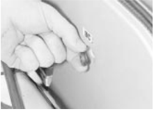
 7.6b . . . and the rubber bush

 7.6c The belt cover seal
![]()
![]()
![]()
![]()
![]()
![]()
![]()
![]()
![]()
![]()
![]()
![]()
![]()
![]()
![]()
![]()
![]()
![]()
![]()
![]()
![]()
![]()
![]()
![]()
![]()
![]() 6 Oil pressure
regulating valve - removal and
refitting
6 Oil pressure
regulating valve - removal and
refitting
Refer to Chapter 2B, Section 6.
![]() 7 Camshaft
toothed belt - removal and refitting
7 Camshaft
toothed belt - removal and refitting
Note: The camshaft toothed belt must be renewed every time it is removed, even if it is apparently in good condition.
Removal
1 Raise and support the front of the vehicle
(see Jacking and Vehicle Support"). Remove the engine undertray and the wheel arch splash shields as a unit.
2 Disconnect the battery negative lead.
3 Unclip the throttle cable from the air
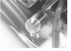
 7.8a Pulley notch and pointer must be aligned . .
.
cleaner-to-air mass meter trunking. Slacken the clips and remove the trunking.
4 Remove the air cleaner as described in
Chapter 4B.
![]()
![]()
![]()
![]()
![]()
![]()
![]()
![]()
![]()
![]()
![]()
![]()
![]()
![]()
![]()
![]()
![]()
![]()
![]()
![]()
![]()
![]()
![]()
![]()
![]()
![]()
![]()
![]() 5 Remove the steering pump drivebelt (when applicable) and the alternator drivebelt.
5 Remove the steering pump drivebelt (when applicable) and the alternator drivebelt.
6 Remove the three bolts and rubber bushes which secure the camshaft toothed belt cover. Remove the cover and its seal (see illustrations .
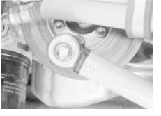
7 Working through the wheel arch, slacken the six screws with splined heads which secure the crankshaft pulley to the sprocket. For better access, unbolt the oil cooler hose clip from the inner wing.
8 Turn the crankshaft until the timing mark on the pulley is in line with the pointer and the timing marks on the camshaft sprockets are in line with the notches on the backplate (see illustrations) (To turn the crankshaft by means of the central bolt, a Torx socket, size
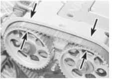
 7.8b . . . and sprocket marks align with backplate
notches (arrowed)
E20, will be needed. If this is not available, engage 4th or 5th gear and turn the crankshaft by turning a front wheel. It is easier to do this smoothly if the spark plugs are removed).
9 Remove the six screws with splined heads and lift off the crankshaft pulley. The screw holes are offset so it will only fit one way.
0 Slacken the camshaft belt tensioner screw using a mm Allen key (see illustration). Move the tensioner to slacken the belt and slip the belt off the sprockets and rollers.
1 Do not turn the crankshaft or camshafts while the belt is removed, or piston/valve contact may occur.
Refitting
2 Commence refitting by checking that the pulley and sprocket timing marks are still correctly aligned. Temporarily refit the pulley and secure it with two screws to do this. When satisfied, remove the pulley.
3 Fit the new belt over the sprockets and rollers, being careful not to kink it. Observe any arrows or other indication of running direction.
4 Refit the crankshaft pulley. Secure it with the six screws with splined heads, tightened to the specified torque (see illustration .
5 The belt tension must now be set. The makers specify the use of a special tool
(KM-666); if this is available, proceed as follows (see illustration .
6 Fit the special tool to the tensioner. Make sure the tensioner is free to move.
7 Make a mark on the exhaust camshaft sprocket, seven teeth anti-clockwise from the timing mark. Turn the crankshaft clockwise
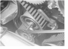
 7.10 Slackening the camshaft belt tensioner screw
7.14 Tightening one of the crankshaft pulley screws

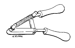
 7.15 Special tool KM-666 for tensioning the
camshaft toothed belt
![]() DOHC (16-valve) engine
2C.5
DOHC (16-valve) engine
2C.5
serious. The only way to be certain that tension is correct is to use the maker's tool, or to have a Vauxhall garage carry out the work.
0 Whichever tensioning method was used, now turn the crankshaft through two full turns clockwise and check that the pulley and sprocket timing marks come back into correct alignment. If they do not, remove the belt and start again.
1 The remainder of refitting is the reverse of the removal procedure.
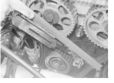
 7.18 Checking the belt tension using a spring
balance and ruler
until the new mark is aligned with the notch on the belt backplate. In this position tighten the tensioner screw to the specified torque, then remove the special tool.
8 If the special tool is not available, belt tension must be set by hand. Move the tensioner using a square drive in the hole provided, nip up the screw and check the tension. As a guide, tension is correct when the belt cannot quite be twisted through ° by hand in the middle of the run between the exhaust camshaft sprocket and the idler roller. If a spring balance is available, correct tension is indicated when in the same place the belt is deflected mm by a load of kg (see illustration). When tension is correct, tighten the tensioner screw to the specified torque.
9 It must be emphasised that the method of setting belt tension without the special tool is given as a guide only. The consequences of a belt slipping or breaking in service could be
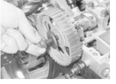

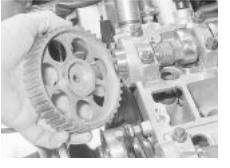
 10.3a Removing a camshaft
sprocket bolt and washer
![]()
![]()
![]()
![]()
![]()
![]()
![]()
![]()
![]()
![]()
![]()
![]()
![]()
![]()
![]()
![]()
![]()
![]()
![]()
![]()
![]()
![]()
![]()
![]()
![]()
![]()
![]()
![]()
![]()
![]()
![]()
![]()
![]()
![]()
 8 Camshaft
toothed belt tensioner and idler rollers - removal and refitting
Removal
1 Remove the toothed belt as described in
Section 7.
2 Remove the Allen screw which secures the belt tensioner. Lift off the tensioner and its mounting plate and recover the spacer sleeve.
3 Similarly unbolt and remove the idler roller and recover its sleeve.
4 Renew the rollers if they show roughness when spun, or if they have been noisy in operation.
Refitting
5 Refitting is the reverse of the removal procedure, noting the following points:
a) Make sure the spacer sleeves are the right way round. The smaller diameter of the tensioner sleeve goes towards the block. The smaller diameter of the idler sleeve goes away from the block.
b Tighten the screws to the specified torque.
c) Fit a new camshaft toothed belt.
![]()
![]()
![]()
![]()
![]()
![]()
![]()
![]()
![]()
![]()
![]()
![]()
![]()
![]()
![]()
![]()
![]()
![]()
![]()
![]()
![]()
![]()
![]()
![]()
![]()
![]()
![]()
![]()
![]()
![]()
![]()
![]()
![]()
![]()
![]()
![]()
![]()
![]()
![]()
![]()
![]()
![]() 9 Camshaft
sprocket oil seals - renewal
9 Camshaft
sprocket oil seals - renewal
1 Remove the camshaft toothed belt as described in Section 7.
2 Remove the camshaft cover and the camshaft sprockets, as described in paragraphs 1 to 4 of Section 10.
3 Punch or drill a small hole in the face of one of the oil seals. Screw in a self-tapping screw
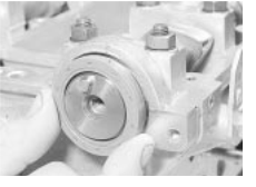
 9.4a Fitting a new camshaft oil seal
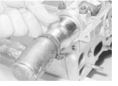
 9.4b Seating a camshaft oil seal
![]() and use this to lever the seal out. Clean the seal seat.
and use this to lever the seal out. Clean the seal seat.
Grease the lips of a new seal and fit it, lips inwards. Seat the seal by tapping it home 2C
using a mallet and a large socket or a piece of tube (see illustrations .
Repeat the operations on the other oil seal.
The remainder of refitting is the reverse of the removal procedure. Fit a new camshaft toothed belt as described in Section 7.
![]()
![]()
![]()
![]()
![]()
![]()
![]()
![]()
![]()
![]()
![]()
![]()
![]()
![]()
![]()
![]()
![]()
![]()
![]()
![]()
![]()
![]()
![]()
![]()
![]()
![]()
![]()
![]()
![]()
![]()
![]()
![]()
![]()
![]() Camshafts - removal and refitting
Camshafts - removal and refitting
Removal
Remove the camshaft toothed belt as described in Section 7.
 2 Remove the spark plug cover, which is retained by two Allen screws. Disconnect the breather hoses from the camshaft cover, re-
move the Allen screws and the camshaft
cover itself.
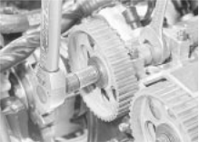
3 Hold a camshaft using an open-ended spanner on the flats provided towards the sprocket end. Without allowing the camshaft to move (risk of piston-to-valve contact) slacken the sprocket bolt. Remove the bolt, washer and sprocket (see illustrations .
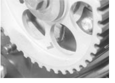
4 Repeat the operation on the other camshaft. Although both sprockets appear to be identical, it is good practice not to get them mixed up. The exhaust sprocket on the engine shown here is marked 'L'; the inlet sprocket is unmarked (see illustration .
10.3b Removing a camshaft sprocket 10.4 Exhaust camshaft sprocket is marked
'L'
Remove the distributor (Chapter 5C).
![]() 2C.6 DOHC
(16-valve) engine
2C.6 DOHC
(16-valve) engine
Matching numbers on bearing cap and cylinder head
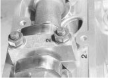
Check that the camshaft bearing caps carry identification numbers, and note which way round they are fitted. The inlet camshaft caps are numbered to the exhaust camshaft caps to Corresponding numbers are cast in the cylinder head (see illustration .
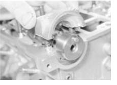
7 Progressively slacken the bearing cap nuts, half a turn at a time until the valve spring pressure has been released. Do not overlook the two extra nuts on the cap which forms part of the distributor housing (see illustration) Remove the nuts and washers and lift off the caps. Be careful that a camshaft does not spring up suddenly when removing the caps.
8 Remove the camshafts with their oil seals. Be careful when handling them, as the edges of the lobes are sharp. Remove the oil seals. Refitting
9 Commence refitting by generously oiling the camshaft bearing surfaces and lobes. If fitting new camshafts, apply the special assembly lubricant provided.
0 Apply sealant to the mating faces of the bearing caps which house the oil seals (Nos 1 and and to the one which houses the distributor drive (No 11).
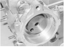
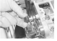
1 Place the camshafts in position with the sprocket locating pins uppermost. Fit the bearing caps, in their correct positions and the right way round, and the nuts and washers
(see illustration
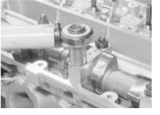
2 Tighten the bearing cap nuts half a turn at a time in progressive sequence so the camshafts are pulled down evenly. Finally tighten them to the specified torque (see illustration
3 Fit new oil seals as described in Section 9.
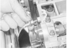
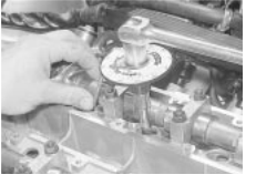
4 Refit the sprockets to their respective camshafts. Fit the sprocket bolts and tighten them to the specified torque, holding the camshafts with a spanner on the flats to prevent rotation (see illustration .
5 Using a strap wrench on the sprocket or a spanner on the sprocket bolt, carefully move each camshaft a little way to verify that it is free to turn. If the cylinder head is installed on the engine, be careful that piston-to-valve contact does not occur. If a camshaft will not turn, it may be that the bearing caps have been fitted the wrong way round.
6 Refit the distributor and the camshaft cover.

![]()

 Distributor housing bearing cap has two extra
nuts
 Tightening a camshaft bearing cap nut
7 Fit a new camshaft toothed belt as described in Section 7.
8 If new camshafts have been fitted, it is suggested that the running-in schedule specified in Chapter 2B, Section 9, paragraph
14, be observed.
![]() 11 Cylinder head - removal and refitting
11 Cylinder head - removal and refitting
Note The procedure described here is the removal of the cylinder head leaving the inlet manifold and fuel injection equipment in place. If preferred, the manifold can be removed with the head after making the appropriate disconnections.
Removal
Remove the camshaft toothed belt as described in Section 7.
 Disconnecting the small breather hoses from
the camshaft cover
Fitting a camshaft bearing cap
 Tightening a camshaft sprocket bolt
2 Disconnect the multi-plug from the air mass meter. Undo the four or five Allen screws, release the idle speed adjuster hose and remove the volume chamber and air mass meter together.
![]()
![]()
![]()
![]()
![]()
![]()
![]()
![]()
![]()
![]()
![]()
![]()
![]()
![]()
![]()
![]()
![]()
![]()
![]()
![]()
![]()
![]()
![]()
![]()
![]()
![]()
![]()
![]()
![]()
![]()
![]()
![]()
![]()
![]()
![]()
![]()
![]()
![]()
![]() 3 Drain the cooling system by disconnecting the radiator bottom hose
(see Chapter 1).
3 Drain the cooling system by disconnecting the radiator bottom hose
(see Chapter 1).
4 Disconnect the accelerator cable.
5 Remove the nine nuts which secure the inlet manifold. They have deformed threads so they are stiff. A socket with a universal joint or
'wobble drive' will be needed to reach some of the nuts.
6 Cut the cable-tie which secures the injector wiring harness to the cylinder head.
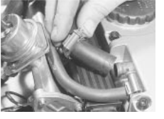
7 Disconnect the two small breather hoses from the camshaft cover (see illustration .
8 Unbolt the support bracket from the base of the inlet manifold (see illustration). Slide the manifold off the cylinder head studs. Be careful not to strain the fuel hoses or the wiring.
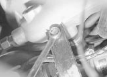
 Unbolting the inlet manifold support bracket
(seen from below)
![]() DOHC (16-valve) engine 2C.7
DOHC (16-valve) engine 2C.7
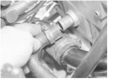
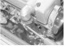
 Disconnecting the heater hose from the
cylinder head
 Disconnecting the large breather hose
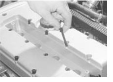
 Removing a camshaft cover screw
9 Remove the exhaust manifold (Chapter 4B).
0 Remove the radiator top hose.
1 Disconnect the heater hose from below the distributor (see illustration .
2 Remove the spark plug lead cover secured by two Allen screws. Disconnect the HT leads from the plugs and move them aside.
3 Remove the distributor (Chapter 5C).
4 Remove the thermostat housing (Chapter
5 Disconnect the large breather hose from the camshaft cover (see illustration). Unbolt the hose bracket from the cylinder head.
6 Remove the 20 Allen screws which secure the camshaft cover (see illustration . Remove the cover.
7 Remove the camshaft sprockets (Section
8 Remove the two Torx screws which
secure the top of the belt backplate to the cylinder head. Also remove the rubber bush and unscrew the belt cover mounting stud
(see illustrations
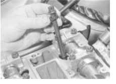
9 Using a size E12 Torx socket, slacken the cylinder head bolts a quarter-turn each in the sequence shown. In the same sequence slacken the bolts a further half-turn, then undo them completely and remove them (see illustrations) Recover the washers. New bolts must be used when refitting.
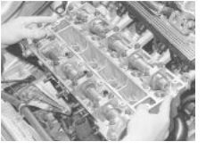
0 Lift off the cylinder head, pulling the inlet manifold back towards the bulkhead slightly if necessary (see illustration . Be careful not to bend the belt backplate. Put the head down on two blocks of wood so that it does not rest on the protruding valves.
1 Recover the gasket from the cylinder block and clean the mating surface, being
careful not to get any debris into the cylinder bores. Cover the open bores, or stuff oily rags into them, to protect them if the head is going to be off for more than a few hours. Refitting
2 Commence refitting by placing a new head gasket onto the block, making sure that it fits over the locating dowels and that it is the right way up (see illustration) It is marked
'OBEN/TOP'.
3 Lower the head onto the block and fit it onto the dowels. Fit the washers to the new bolts, fit the bolts and tighten them finger tight.
![]() 4 Following the sequence shown, tighten
4 Following the sequence shown, tighten
the bolts through the first four stages given in 2C
the Specifications (see illustrations .
 11.18a Remove the rubber bush . . .
11.18b . . . and the belt cover mounting stud


 11.19a Cylinder head bolt slackening sequence
 11.19b Removing a cylinder head bolt and washer
 Lifting off the cylinder head
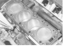
 New head gasket in position
![]() 2C.8 DOHC
(16-valve) engine
2C.8 DOHC
(16-valve) engine


 11.24a Cylinder head bolt tightening sequence
5 The remainder of refitting is a reversal of the removal procedure, noting the following points:
a) Use new gaskets on the thermostat housing, the manifolds and the camshaft cover (see illustration
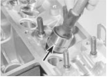
 12.4 Removing a tappet.
Note the oil ring
(arrowed)
11.24b Angle tightening a cylinder head bolt
b) Use a new camshaft toothed belt and tension it as described in Section 7.
c) Tighten all fastenings to the specified torque.
d) Run the engine until the cooling fan cuts in. If the hydraulic tappets have been disturbed, they may be noisy for a few minutes until they settle down. Switch the engine off, remove the camshaft cover again and tighten the cylinder head bolts through the final specified stage.
![]() 12 Cylinder head - overhaul
12 Cylinder head - overhaul
Remove the manifold gaskets
2 Remove the camshafts, slackening the bearing cap nuts progressively until the valve spring pressure is released.
3 Remove the spark plugs.
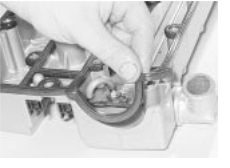
 Fitting a new gasket to the camshaft cover
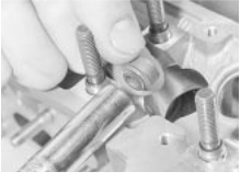
4 Using a sucker or a magnet, remove the hydraulic tappet buckets from their bores (see illustration) If they are to be re-used, keep them in order so that they can be refitted to their original locations. To stop the oil draining out of them, store them in a bath of clean engine oil with the oil ring lowermost.
5 Prepare a box with compartments to receive the valve components. Using a valve spring compressor and a piece of tube with two slots cut in it, compress a valve spring
![]()
![]()
![]()
![]()
![]()
![]()
![]()
![]()
![]()
![]()
![]()
![]()
![]()
![]()
![]()
![]()
![]()
![]()
![]()
![]()
![]()
![]()
![]()
![]()
![]()
![]()
![]()
![]()
![]()
![]()
![]()
![]()
![]()
![]()
![]() (see illustration . Extract the collets from the
top of the valve stem using a pencil magnet or a magnetic screwdriver.
(see illustration . Extract the collets from the
top of the valve stem using a pencil magnet or a magnetic screwdriver.
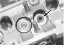
Carefully release the compressor and remove the valve, the spring upper seat and the spring. Pull off the valve stem oil seal with longnosed pliers and recover the valve spring seat. Place all the components in the appropriate compartment in the box (see illustrations .
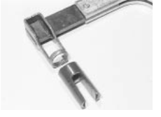
 Detail of valve spring compressor head and
tube
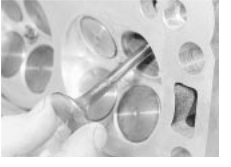
 12.6a Remove the valve . . .
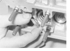
 12.6b . . . the spring upper seat . . .
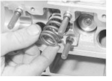
 12.6c . . . the valve spring . . .
 12.6d . . . the valve stem
oil seal
(arrowed) . . .
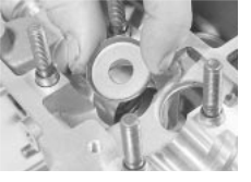
 12.6e . . . and the valve spring seat
![]() DOHC (16-valve) engine 2C.9
DOHC (16-valve) engine 2C.9
 12.12a Fit a valve stem oil seal into a socket or
tube . . .
7 Repeat the operations on the other 5
valves.
8 Clean the combustion chambers and the gasket mating faces with a wooden or plastic scraper. Finish up with a rag or toothbrush and a solvent such as a proprietary carburettor cleaner.
9 Inspect the valves, springs and seats as described in Chapter 2A, Section , paragraphs to Note however that the exhaust valves on these engines are filled with sodium to improve heat transfer. Sodium is a highly reactive metal which will ignite or explode spontaneously on contact with air or water. Valves containing sodium must not be disposed of in ordinary scrap.
0 Check the head gasket mating face for distortion using a straightedge and feeler blades. Check crosswise, lengthwise and diagonally. Warp limits are given in the Specifications.
1 Inspect the camshafts and their bearing surfaces and caps as described in Section 24.
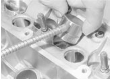
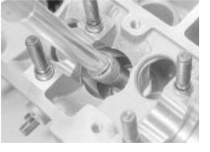
2 Commence reassembly by fitting a valve spring seat to its location. Fit a new valve stem oil seal to the top of the valve guide, using a deep socket or a piece of tube (see illustrations .
3 Oil the valve stem and insert the valve into its guide, passing it gently through the stem oil seal to avoid damage. Fit the valve spring and upper seat. Compress the spring and fit the collets using a magnetic screwdriver this is a fiddly business. A dab of grease on each collet will keep them in position on the valve stem (see illustration .
4 Carefully release the valve spring
 12.16a Oiling a tappet . . .
 12.12b . . . and press it home
compressor. Apply a solid tube or piece of wood (eg a hammer handle) to the top of the valve and tap smartly with a hammer to settle the components.
5 Repeat the operations on the other valves.
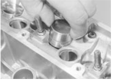
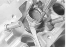
Refit the tappets, with the oil ring lowermost, oiling them generously (see illustrations) If new camshafts are to be fitted, apply some of the assembly lubricant supplied with new camshafts to the top surfaces of the tappets.
7 Fit the camshafts and their oil seals as described in Section 10.
8 The distributor and spark plugs may be refitted now, or if preferred left until after the head has been refitted.
![]()
![]()
![]()
![]()
![]()
![]()
![]()
![]()
![]()
![]()
![]()
![]()
![]()
![]()
![]()
![]()
![]()
![]()
![]()
![]() 13 Sump and oil baffle plate - removal
and refitting
13 Sump and oil baffle plate - removal
and refitting
Removal
1 Raise and support the front of the vehicle
(see "Jacking and Vehicle Support . Disconnect the battery earth (negative) lead.
2 Drain the engine oil.
3 Remove the exhaust manifold (Chapter 4).
4 Disconnect the multi-plug from the engine oil level sensor.
5 Remove the flywheel cover plate.
6 Remove the sump retaining bolts. Remove the sump, tapping it with a hide or plastic mallet if necessary to break the joint.
7 Remove the oil pick-up pipe and its bracket, followed by the baffle plate.
8 Remove the old gaskets and clean the mating surfaces.
 12.16b . . . and fitting it to its bore
 Fitting a valve collet
Refitting
9 Commence refitting by applying sealant to the oil pump housing joint and the rear main bearing cap joint.
0 Apply sealant to a new gasket and fit the gasket to the block. Make sure that the locating dowels are in position.
1 Fit the baffle plate to the block. Refit the oil pick-up pipe and bracket, using a new O-ring between the pipe and the pump and applying sealant to the bolt threads.
2 Fit another new gasket, this time without sealant, between the baffle plate and the sump. Fit the sump, apply sealant to the bolt threads and insert and tighten the bolts.
![]() 3 The remainder of refitting is the reverse of the removal procedure. Remember to refit and
tighten the drain plug and to refill the engine
3 The remainder of refitting is the reverse of the removal procedure. Remember to refit and
tighten the drain plug and to refill the engine
with oil on completion. 2C
![]()
![]()
![]()
![]()
![]()
![]()
![]()
![]()
![]()
![]()
![]()
![]()
![]()
![]()
![]()
![]()
![]()
![]()
![]()
![]()
![]()
![]()
![]()
![]()
![]()
![]()
![]()
![]()
![]()
![]()
![]()
![]()
![]()
![]() 14 Oil pump - removal and refitting
14 Oil pump - removal and refitting
Removal
1 Remove the camshaft toothed belt as described in Section 7.
2 Disconnect the oil cooler lines from the filter housing and move them aside. Be prepared for oil spillage.
3 Remove the camshaft cover and both camshaft sprockets (see Section 10).
4 Remove the belt tensioner and idler rollers.
5 Remove the crankshaft sprocket central bolt, using an E20 Torx socket. The bolt is very tight prevent the crankshaft turning by engaging a gear, chocking the wheels and applying the handbrake, or remove the flywheel cover plate and have an assistant jam the ring gear teeth.
6 Remove the crankshaft sprocket, using a puller if necessary. Note how the tang on the sprocket engages with the keyway in the crankshaft. Recover the spacer from behind the sprocket. Remove the timing belt backplate.
7 Remove the sump, oil pick-up pipe and baffle plate as described in Section 13.
8 Unbolt the oil pump from the block and remove it. Clean the pump and block mating faces.
![]() 2C.10 DOHC
(16-valve) engine
2C.10 DOHC
(16-valve) engine
Refitting
9 Commence refitting by smearing a new gasket with grease and placing it on the pump. Grease the lips of the oil seal and refit the pump, being careful not to damage the oil seal as it passes over the crankshaft.
0 Insert the pump securing bolts. Position the bottom of the pump flush with the sump mating face of the block and tighten the bolts to the specified torque.
1 Thinly coat the outer face of the spacer with sealant to GM spec 15 04 200/8 983 368
(see Chapter 2B, Section paragraph . Push the spacer onto the crankshaft.
2 The remainder of refitting is the reverse of the removal procedure. Remember to fit a new camshaft toothed belt.
![]() 15 Oil pump - overhaul
15 Oil pump - overhaul
Refer to Chapter 2B, Section 14.
![]()
![]()
![]()
![]()
![]()
![]()
![]()
![]()
![]()
![]()
![]()
![]()
![]()
![]()
![]()
![]()
![]()
![]()
![]()
![]()
![]()
![]()
![]()
![]()
![]()
![]()
![]()
![]()
![]()
![]() 16 Oil cooler thermostatic valve
16 Oil cooler thermostatic valve
![]() - removal and refitting
- removal and refitting
Removal
1 The thermostatic valve is mounted in the oil cooler adapter, just above the oil filter.
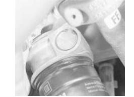
2 Place a drain tray under the filter housing. Remove the circlip from the end of the valve
(see illustration
3 Recover the plug, spring and thermostatic element. There will be some oil spillage.
4 Clean and examine the components: renew any which are obviously worn or damaged. Refitting
5 Refitting is the reverse of the removal procedure. Check the engine oil level and top- up if necessary.
![]() 17 Crankshaft front oil seal - renewal
17 Crankshaft front oil seal - renewal
1 Remove the crankshaft sprocket as described in the procedure for oil pump removal. There is no need to remove the cam- shaft sprockets or belt backplate. Recover the spacer from behind the sprocket.
2 Drill or punch a small hole in the face of the oil seal. Screw in a self tapping screw and use this to lever out the seal. Clean the seal seat.
3 Grease the lips of a new oil seal. Fit the seal, lips inwards, and seat it using a piece of tube, some washers and the crankshaft sprocket bolt.
4 Thinly coat the outer face of the spacer with sealant to GM spec 15 04 200/8 983 368 (see Chapter 2B, Section 20, paragraph 17). Push the spacer onto the crankshaft.
5 The remainder of refitting is the reverse of the removal procedure. Remember to fit a new camshaft toothed belt.
![]()
![]()
![]()
![]()
![]()
![]()
![]()
![]()
![]()
![]()
![]()
![]()
![]()
![]()
![]()
![]()
![]()
![]()
![]()
![]()
![]()
![]()
![]()
![]()
![]()
![]()
![]()
![]()
![]()
![]()
![]()
![]()
![]()
![]()
![]()
![]() Circlip securing oil cooler thermostatic
valve
Circlip securing oil cooler thermostatic
valve
![]()
![]()
![]()
![]()
![]()
![]()
![]()
![]()
![]()
![]()
![]()
![]()
![]()
![]()
![]()
![]()
![]()
![]()
![]()
![]()
![]()
![]()
![]()
![]()
![]()
![]()
![]()
![]()
![]()
![]()
![]()
![]()
![]()
![]()
![]()
![]()
![]()
![]()
![]()
![]() 18 Pistons and connecting rods
18 Pistons and connecting rods
![]() - removal and refitting
- removal and refitting
Refer to Chapter 2A, Section but note that the pistons and rods may be separated if wished, as described in Section 19.
![]()
![]()
![]()
![]()
![]()
![]()
![]()
![]()
![]()
![]()
![]()
![]()
![]()
![]()
![]()
![]()
![]()
![]()
![]()
![]()
![]()
![]()
![]()
![]()
![]()
![]()
![]()
![]()
![]()
![]()
![]()
![]()
![]()
![]()
![]()
![]()
![]()
![]()
![]() 19 Pistons and connecting rods
19 Pistons and connecting rods
![]() - dismantling and reassembly
- dismantling and reassembly
1 With the pistons and connecting rods removed they may be separated if necessary as follows.
2 Note the relative orientation of rod and piston. When fitted, the arrow on the piston crown points to the camshaft sprocket end of the engine, and the bosses on the connecting rod face towards the flywheel.
![]()
![]()
![]()
![]()
![]()
![]()
![]()
![]()
![]()
![]()
![]()
![]()
![]()
![]()
![]()
![]()
![]()
![]()
![]()
![]()
![]()
![]()
![]()
![]()
![]()
![]()
![]()
![]()
![]()
![]()
![]()
![]()
![]()
![]()
![]()
![]()
![]()
![]()
![]() 3 Remove one of the circlips which secure the gudgeon pin. Push the gudgeon pin out of the piston and connecting rod using a wooden or brass rod. No great force should
be necessary.
3 Remove one of the circlips which secure the gudgeon pin. Push the gudgeon pin out of the piston and connecting rod using a wooden or brass rod. No great force should
be necessary.
![]()
![]()
![]()
![]()
![]()
![]()
![]()
![]()
![]()
![]()
![]()
![]()
![]()
![]()
![]()
![]()
![]()
![]()
![]()
![]()
![]()
![]()
![]()
![]()
![]()
![]()
![]()
![]()
![]()
![]()
![]()
![]()
![]()
![]()
![]()
![]()
![]()
![]()
![]() 4 When refitting, fit the connecting rod into the piston and make sure they are the right way round. Oil the gudgeon pin and push it
home, then secure it with the circlip.
4 When refitting, fit the connecting rod into the piston and make sure they are the right way round. Oil the gudgeon pin and push it
home, then secure it with the circlip.
![]() 20 Flywheel - removal and refitting
20 Flywheel - removal and refitting
Removal
1 Remove the clutch assembly as described in Chapter 6.
2 Mark the position of the flywheel relative to the crankshaft. Jam the ring gear teeth and slacken the flywheel retaining bolts (see Chapter 2A, Section 16).
3 Remove the bolts and lift off the flywheel. Do not drop it, it is heavy. Obtain new bolts for reassembly.
Refitting
4 Refitting is the reverse of the removal procedure. Tighten the bolts to the specified torque.
![]()
![]()
![]()
![]()
![]()
![]()
![]()
![]()
![]()
![]()
![]()
![]()
![]()
![]()
![]()
![]()
![]()
![]()
![]()
![]()
![]()
![]()
![]()
![]()
![]()
![]()
![]()
![]()
![]()
![]()
![]()
![]()
![]()
![]()
![]()
![]()
![]()
![]()
![]() 21 Crankshaft rear oil seal - renewal
21 Crankshaft rear oil seal - renewal
Remove the flywheel as described in
![]()
![]()
![]()
![]()
![]()
![]()
![]()
![]()
![]()
![]()
![]()
![]()
![]()
![]()
![]()
![]()
![]()
![]()
![]()
![]()
![]()
![]()
![]()
![]()

![]()
 Section 20.
Renew the oil seal as described in Chapter
2A, Section 19.
22 Engine/transmission mountings - removal and refitting
Refer to Chapter 2A, Section 17.
![]()
![]()
![]()
![]()
![]()
![]()
![]()
![]()
![]()
![]()
![]()
![]()
![]()
![]()
![]()
![]()
![]()
![]()
![]()
![]()
![]()
![]()
![]()
![]()
![]()
![]()
![]()
![]()
![]()
![]()
![]()
![]()
![]()
![]()
![]()
![]()
![]()
![]() 23 Crankshaft
and main bearings
23 Crankshaft
and main bearings
![]() - removal and refitting
- removal and refitting
Refer to Chapter 2B, Section 20.
![]() 24 Engine components - examination and renovation
24 Engine components - examination and renovation
1 The cylinder head and oil pump have been considered earlier in this Chapter. For other components refer to Chapter 2A, Section 21, and note the following additional information. Camshafts
2 With the camshafts removed, examine the bearing surfaces and lobes for wear, pitting and scuffing. Measure the bearing journals with a micrometer. Dimensions are given in the Specifications.
3 Wear or damage to a camshaft means that it must be renewed. If there is corresponding wear in the bearing seats and caps, a complete new cylinder head will be required. The bearing caps are line bored in position on the head and cannot be renewed separately.
4 With the camshafts fitted to the head, check their endfloat using a dial gauge or feeler blades. Endfloat outside the limits specified means that the camshaft(s) and/or cylinder head must be renewed.
Camshaft toothed belt
5 As mentioned earlier, the belt must be renewed every time that it is removed, even if it appears to be in good condition. Piston/bore grade marks
6 The number or code denoting the piston and bore grade (see Specifications) is stamped on the block near the engine number.
![]()
![]()
![]()
![]()
![]()
![]()
![]()
![]()
![]()
![]()
![]()
![]()
![]()
![]()
![]()
![]()
![]()
![]()
![]()
![]()
![]()
![]()
![]()
![]()
![]()
![]()
![]()
![]()
![]()
![]()
![]()
![]()
![]()
![]()
![]()
![]()
![]()
![]()
![]()
![]()
![]() 25 Engine - removal and refitting
25 Engine - removal and refitting
Removal
1 The engine is removed with the transmission by lowering the two out of the engine bay. They can then be separated on the bench.
DOHC (16-valve) engine 2C.11
![]() 2 Disconnect both leads from the battery.
2 Disconnect both leads from the battery.
3 Depressurise the fuel system (Chapter 4B).
4 Remove the bonnet.
5 Remove the air cleaner (Chapter 4B).
6 Disconnect the idle adjuster hose from the pre-volume chamber. Remove the screws from the pre-volume chamber, disconnect the multi-plug from the air mass meter and remove the pre-volume chamber and air mass meter together.
7 Drain the cooling system (Chapter 1).
8 Disconnect all coolant and heater hoses from the engine.
9 Disconnect the brake servo vacuum hose at the servo.
0 Disconnect the accelerator cable.
1 Disconnect the fuel supply and return pipes from the fuel injector rail. Be prepared for fuel spillage. Release the pipes from any clips or ties and move them out of the way.
2 Remove the exhaust manifold securing nuts and heat shield.
3 Disconnect the engine wiring harness multi-plug next to the expansion tank.
4 Disconnect the multi-plugs from the fuel injectors and the throttle valve switch. Also unbolt the earth straps from the fuel rail.
5 Disconnect the HT distributor-to-ignition coil lead and the LT multi-plug from the distributor.
6 Disconnect the wiring harness multi-plug at the left-hand suspension turret.
7 In the area of the right-hand suspension turret, disconnect the multi-plugs for the inductive pulse sensor and (if applicable) the vent valve and the oxygen sensor.
8 Disconnect the wiring from the two temperature sensors on the thermostat housing.
9 On the rear of the engine disconnect the multi-plugs from the knock sensor, the idle speed adjuster and the oil temperature switch.
0 Disconnect the oil level sensor and the reversing light switch.
1 Unbolt the earth strap from the transmission.
2 Disconnect the speedometer cable, or disconnect the speedometer sender multi-plug, as applicable (see illustration .
3 Engage second gear, then disconnect the gearchange remote control by undoing the pinch-bolt.
4 Disconnect the clutch cable.
5 Slacken the front wheel bolts, raise and securely support the front of the car and remove the front wheels (see "Jacking and Vehicle Support").
On models with power steering, remove the pump drivebelt. Unbolt the pump and move it aside without disconnecting its hoses. Support it so that the hoses are not strained.
7 Disconnect the oil cooler lines from the filter housing. Be prepared for oil spillage.
8 Remove the exhaust manifold (Chapter
4B).
9 Separate the control arm balljoints from the steering knuckles (see Chapter 10).
0 Separate the driveshafts from the final drive housing (see Chapter 8). Be prepared for oil spillage. Plug the holes and tie the driveshafts up out of the way.
1 Attach the lifting tackle to the engine/transmission and take the weight. Check that no cables, hoses etc are still attached or are otherwise in the way.
2 Unbolt the engine/transmission mountings in the following order:
a) LH front. b) Rear.
c) RH front.
3 Carefully lower the assembly through the engine bay to the ground. If necessary lift the vehicle off the engine to enable it to be withdrawn.
Refitting
4 When refitting, apply thread-locking compound to the engine/ transmission mounting bolts. Tighten them finger tight at
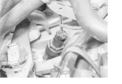
 Speedometer sender (used with digital
instrument panel)
first, then to the specified torque in the following order:
a) LH front. b) RH front. c) Rear
5 The remainder of refitting is the reverse of the removal procedure.
![]() 26 Engine - initial start-up after overhaul
26 Engine - initial start-up after overhaul
1 Refer to Chapter Section but disregard the instructions to check the idle speed and valve clearances.
![]() 2 If new camshafts have been fitted, it is suggested that the running-in schedule specified in Chapter 2B, Section 9, paragraph
2 If new camshafts have been fitted, it is suggested that the running-in schedule specified in Chapter 2B, Section 9, paragraph
14, be observed.
3 Run the engine until the cooling fan cuts in. 2C
If the hydraulic tappets have been disturbed, they may be noisy for a few minutes until they settle down.
4 Switch the engine off, remove the camshaft cover and tighten the cylinder head bolts through the final specified stage.
|