SECTION 1
KEY RULES HIGHLIGHT COMMON WELL
CONTROL PROBLEMS
A lot has been learned about well pressures in the last 10 years. Blowout control has been developed until it is now accepted as a basic supervisory and crew responsibility. Since control of a well is so critical, the industry trains its crews on the essentials of blowout co 20120t199u ntrol. Schools are held throughout the world, using wells and rig equipment as well kick conditions to teach and practice these procedures.
However, as with any skill learned but not used for a time, these procedures must be reviewed periodically if they are to be maintained.
This series of practical problems in pressure control, beginning with this first section, will serve as a review of well killing and control procedures. Since the problems are actually used in teaching rig crews, all of them have reasonable solutions. Also every situation described has occurred enough in actual wells to constitute a typical blowout situation.
No abbreviated set of rules or procedures can take the place of primary instruction in blowout control. In-depth training and on-site practice are essential.
The following pressure control rules serve as a refresher and are organized to highlight everyday problems of well control. Each problem in this manual will illustrate at least one of the following well-pressure control rules.
RULE 1: SHUT IN THE WELL KICK AS SOON AS POSSIBLE
A potential blowout is signalled by a sequence of events that starts with increased flow at the flow line. This is followed by an increase in pit volume, and finally by the arrival of gas or water at the surface. By the time pit volume increase or gas at the surface is detected, the well kick may be dangerous due to the size of the influx.
Obviously, the proper way to detect a well kick is by observing the flow increase at the flow line.
If there is any question whether the well is flowing, the pump should be shut off. Continued flow at the flow line indicates gas or other material is entering the well bore. Since turning off the pump reduces bottom hole pressure (BHP) by the amount of the annular pressure drop, the simple flow check is an extremely good procedure.
Occasionally an exception to the significance of the flow check may occur. When the mud density is being increased, the mud in the drill pipe may exert more pressure than the column of mud in the annulus. Under this condition, the drill pipe mud acts as if it had been slugged for a trip. The mud level in the drill pipe drops until the pressure between drill pipe and annulus is equalized. This may cause a false indication of flow. However, this condition produces a very small flow and dies away quickly. If in doubt, shut off the pump and see if the hole will flow. If still not sure, shut the well in and see if any pressure develops on the drill pipe.
As the kick size increases, the problems of well control become more critical. As a general rule well kicks of less than 15 bbl may be killed with very little difficulty. Well kicks of 15 to 30 bbl become rather difficult to control without losing circulation. When a well kick becomes greater than 30 bbl it may be impossible to bring the bubble to the surface without causing lost circulation.
Theoretical models indicate that, with a gas kick, maximum casing pressures increase as the square root of kick size. For example, a 100 bbl kick will have three times the maximum surface pressure of 10 bbl kick.
RULE 2: DETERMINE THE SHUT IN DRILL PIPE PRESSURE
When the well is shut in, the drillpipe (pump) pressure gauge and the casing (annular) pressure gauge are indicators of downhole conditions. The drillpipe pressure is the amount by which the reservoir pressure exceeds that exerted by the column of drilling mud inside the drill pipe.
The casing pressure is the amount by which the reservoir pressure exceeds that exerted by the column of fluid in the annulus. It is usually greater than the drillpipe pressure because reservoir fluid in the annulus is lighter than the drilling mud. The column of mixed fluid in the annulus exerts less pressure than the column of uncut drilling mud in the drill pipe. If it can be assumed that the drill pipe is full of drilling mud of a known density, then the reservoir pressure can be calculated from the shut in drillpipe pressure (SIDPP):
|
|
where:
Pres = reservoir pressure (psi)
MW = Mud Weight (psi/ft)
D = depth of the reservoir (ft)
SIDPP = shut in drillpipe pressure (psi)
Then mud density increase is:
|
|
Where:
f = units conversion (19.12 ppg, 144 lb/ft², 10 kg/lb)
If drillpipe pressure appears to be incorrect, pump slowly for about 1 minute, holding the annulus pressure constant with the adjustable choke. Then, stop the pump and close the choke. If drillpipe pressure has changed, repeat this procedure until the drillpipe pressure holds constant.
This same technique can be used if there is a float in the drill pipe, but it is sometimes better to use the procedure discussed in Rule number 3 (Annulus pressure).
If drillpipe pressure rises very slowly but continuously when the well is shut in, it may be either low formation permeability or gas rising in the well bore.
RULE 3: CIRCULATE USING THE CHOKE
To kill a well, maintain bottom hole pressure (BHP) slightly in excess of reservoir pressure. A reduction in BHP allows the reservoir to flow, and excessive BHP could cause lost circulation followed by reservoir flow.
The best way to hold a constant BHP is to circulate the well using drillpipe pressure as a control. Two pressures are used in this method:
1. The excess of reservoir pressure over mud pressure (SIDPP)
2. Circulating pressure or system pressure loss (SCR).
The initial circulating pressure (ICP) for killing a well is the sum of SIDPP and circulating pressure at a given pump rate.
|
|
To determine normal circulating pressure at a fixed rate, use one of these three approaches:
1. Calculate circulation pressure at given rate. This is an excellent theoretical exercise but is generally less accurate than the others.
2. Check circulation pressures. Lower the pumping rate to about one half the normal circulating rate. A slow rate circulating pressure (SCR) can thus be established. It is best to do this for both pumps. When a kick occurs, calculate the ICP as above, then circulate at the slow rate and maintain the ICP with the constant pump rate and using the adjustable choke. Do not change the pump rate. This is the most accurate technique and it allows the crew to become accustomed to the idea of a slow circulating rate when a kick occurs.
3. Annulus pressure. This approach, first proposed by Goin and O'Brien (1957), has the advantage of flexibility. When the pumps are started, hold annulus pressure constant using the adjustable choke. Once a circulating rate for the well-killing procedure is reached, ignore the annulus pressure and use instead the drillpipe pressure as the ICP with the adjustable choke. Do not change the pump rate.
An advantage of this approach is that it can simply be repeated if pumps are changed. Also, it can be used even when there is no pre-recorded circulating pressure. However, this method may cause a change in BHP from annular pressure drop, gas expansion, and hole geometry changes, and could possibly contribute to lost circulation.
The period of constant annulus pressure must be kept as brief as possible, probably 5 min or less. When gas is near the surface, the constant annular pressure causes a decrease in BHP at a rate proportional to gas volume/pressure relationship.
The best way to determine the ICP is a make a check on the SCR pressure every tour and keep record of it. When a kick occurs, add the SIDPP to the SCR pressure to obtain an ICP value. Then start the pump holding the annulus pressure constant. When the pump is up to the slow rate, the calculated and actual ICPs should be quite close.
RULE 4: REDUCE PUMP RATE BY ONE HALF
During a well-killing procedure use a reduced horsepower or pressure rating. The reduced circulating rate should be half the circulating rate while drilling. Half rate is generally appropriate because using only an eighth of the available horsepower, it develops a quarter of the maximum pressure and thus relieves the mechanical stress on the rig. It also allows enough pressure reserve for SIDPP to be imposed upon circulating pressure. The lower circulating rate improves control of mud density using barite and allows longer reaction time when controlling the choke.
The half-pressure rule is not absolute by any means. However, field experience indicates the slow circulating rate when killing a well will increase reliability of rig machinery, and allow better reaction time.
RULE 5: INCREASE MUD DENSITY
The mud density can be increased after the well kick and before circulating, while circulating, or after the intruding fluid has been circulated out of the hole using one of these methods:
1. The Wait and Weight method. To minimize well-bore pressure the mud density should be increased before circulating. However, a long period of no circulation in soft-formation drilling might result in stuck pipe. High casing pressure due to bubble migration might also result from long periods with no circulation.
2. The Concurrent method. To kill the well kick in the minimum amount of time and reduce the chance of pipe sticking, increase mud density concurrently with mud circulation. Of these operations, this is the most complicated.
3. The Drillers' method. Increase mud weight after the intruding fluid has been circulated out of the hole. This is the simplest technique, but it requires a maximum amount of time and maximum use of surface preventer equipment. It also causes maximum pressures.
Since all of these methods use constant drillpipe pressure to control the well a correction must be made when the new mud enters the drill pipe. When circulating, the drillpipe pressure is the sum of the pressure required to dominate the reservoir and the circulating pressure in the system at a given rate (ICP above). As the new mud density starts down the drill pipe, less and less impressed pressure is required to dominate the reservoir.
From the time the new mud enters the drill pipe until it teaches the bottom of the hole, drillpipe pressure must be gradually reduced. This reduction is about equal to the original SIDPP value.
|
|
Once the new mud starts up the annulus, no further correction is needed.
The calculation of surface-to-bit pump strokes and surface-to-bit circulating time at the given pumping rate should be made each day and kept available for this purpose. The correction in the drillpipe pressure can be made by a simple graphical representation as figure 1-1.
For a final check to surface-to-bit time or pump strokes, stop the pump and shut the well in. The new SIDPP will be zero if the drill pipe is full of the proper weight mud.
RULE 6: CONSTANT CASING PRESSURE
Casing pressure can be used to avoid calculating the system pressure loss and required drillpipe pressure reduction. However, constant casing pressure can cause changes in BHP.
Casing pressure techniques should not be used with wells that have a large annular pressure drop. These are generally very deep, slim holes. Do not use casing pressure techniques if the gas is near the surface. Under these conditions, the potential change in BHP is too great to use casing pressure methods to kill the well.
To obtain ICP, the casing pressure is held constant by use of the choke until the pump rate is at some agreed upon value. Then the pressure showing on the drillpipe gauge will indicate the ICP.
When a change in mud density occurs in the drill pipe, the casing pressure will stay constant if there is neither gas expansion nor change in the length of the invading fluid column in the annulus. Under these conditions, it is possible to hold casing pressure constant while new mud weight is going down the drill pipe. As soon as the new mud weight reaches the bit the drillpipe pressure will be the final circulating pressure (FCP) and this should be used instead of the casing pressure. Maintaining constant casing pressure while changing mud weight in the drill pipe requires good judgment. Errors can be induced by gas expansion, annular pressure loss, and hole geometry.
Therefore, the constant casing pressure method should never be used when gas is near the surface or in a deep, slim hole.
RULE 7: MAINTAIN A MARGIN VALUE
Circulation can be continued with the reservoir dominated by the ICP for as long as desirable. Eventually, however, the density of the drilling fluid must be increased until the mud column dominates the reservoir. The mud weight increase required has already been derived.
To this must be added a margin to compensate for the movement of the mud while withdrawing the drill pipe from the hole (trip margin). This margin may be expressed as the resistance to flow of the mud. The resistance causes a BHP reduction when the drill pipe is raised. The annular pressure drop, converted to equivalent mud density, should be used as the margin value. If this is not available, the Bingham expression for this annular pressure drop is generally satisfactory and easy to use. Using the first half of the term, a general value based on the mud properties and hole diameter can be derived to express a reasonable margin value:
|
|
Where:
Margin = minimum safety factor for coming out of the hole
YP = Yield Point
Dh = hole diameter
Dp = pipe OD
f = units constant
This value, added to the mud density increase, yields the minimum mud weight required to dominate the reservoir when pipe is moving up with the pump off.
Often , casing setting depth is where the mud weight approaches the fracture gradient. Well kicks that occur just before setting pipe are very critical. In these cases minimum margins must be used to avoid lost circulation. Also, the margin value should be calculated with the best available techniques and added to the mud density after the well is killed, but before the trip.
PROBLEMS SERIES
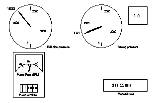
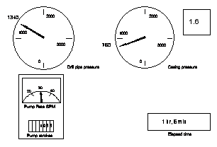
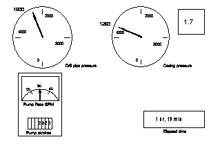
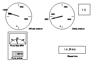
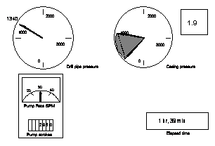
Beginning with the problems in this section, and continuing with those in subsequent sections, a standard choke control panel will be used with each problem.
Pressures will be shown in English and metric terms, for example, psi(kg/cm2).
Pump rate will be given in strokes/min, and pump strokes will be given in total strokes since the problem began unless otherwise indicated.
Elapsed time will be the time since the problem began and mud density will be given as ppg (SG, lb/ft3).
Pit volume increases will be given as bbls (m3).
In each of the upcoming problem series, possible answers to the problem will be listed in the "What should you do?" column, and the correct answers will be given at the end of each group of problems. In cases where two answers are appropriate, it is necessary to choose the step to be performed first.
THE FIRST PROBLEM
This first problem group illustrates the procedure for circulating a kick out of a well when no system pressure loss has been prerecorded by the drill crew.
Important points. The reservoir pressure is balanced when the well is shut in and the pressure on the drillpipe gauge stabilizes. When the correct ICP is maintained at the proper pump rate, the situation is similar to a shut in well (ie the reservoir pressure is balanced). To eliminate the chance of error, the system pressure loss must be recorded once per tour at some convenient slow pump rate (although there are other methods to determine system pressure loss and ICP).
Once the ICP is established at some pump rate, this pressure must be kept constant until the mud density is changed.
When pressure or pump rate rules are violated, either too much or too little pressure is exerted against the formation. This may cause lost circulation or increased fluid flow.
Other comments. The oil-field term "Constant drillpipe pressure" is somewhat misleading. It means that as long as mud density inside the drill pipe is constant, the pump pressure is constant. Pump pressure must be allowed to change when mud density is changed in the drill pipe. Pump rate must always be constant.
|
|
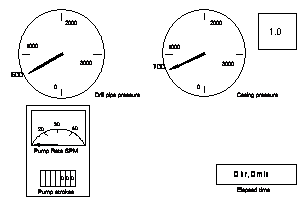
Problem 1-0
A kick has occurred and the well has been shut in. The system pressure loss at 30 spm is 740 psi (52 kg/cm2).
Now calculate the initial circulating pressure and use that pressure to control the well. Do not plan to increase the mud density at this time. Ignore any other pressure considerations.
What is the initial circulating pressure at 30 spm?
|
|
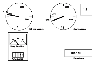
Problem 1-1
The pump has been started and choke is partly open.
What should you do?
1 Increase choke size?
2 Decrease choke size?
3 Increase the pump rate?
4 Decrease the pump rate?
5 Everything is OK - continue?
6 Stop the pump and close the well in?
|
|
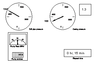
Problem 1-2
Notice the pressures, the pump rate, and the time.
What do you think has happened?
What should you do?
1 Increase choke size?
2 Decrease choke size?
3 Increase the pump rate?
4 Decrease the pump rate?
5 Everything is OK - continue?
6 Stop the pump and close the well in?
|
|
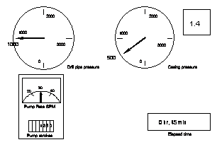
Problem 1-3
Everything is going fine - or is it? The casing pressure has not changed very much.
What should you do:
1 Increase choke size?
2 Decrease choke size?
3 Increase the pump rate?
4 Decrease the pump rate?
5 Everything is OK - continue?
6 Stop the pump and close the well in?
|
|
Problem 1-4
What can you do now? You are letting more gas in the bottom of the hole!
What should you do:
1 Increase choke size?
2 Decrease choke size?
3 Increase the pump rate?
4 Decrease the pump rate?
5 Everything is OK - continue?
6 Stop the pump and close the well in?
|
|
Problem 1-5
What should you do to decrease drillpipe and casing pressure:
1 Increase choke size?
2 Decrease choke size?
3 Increase the pump rate?
4 Decrease the pump rate?
5 Everything is OK - continue?
6 Stop the pump and close the well in?
|
|
Problem 1-6
Now the casing pressure is going up. Maybe the pump rate should not have been changed. What needs to be done now - quickly:
1 Increase choke size?
2 Decrease choke size?
3 Increase the pump rate?
4 Decrease the pump rate?
5 Everything is OK - continue?
6 Stop the pump and close the well in?
|
|
Problem 1-7
Drillpipe pressure and casing pressure are both going up! Has something been done wrong?
What should you do:
1 Increase choke size?
2 Decrease choke size?
3 Increase the pump rate?
4 Decrease the pump rate?
5 Everything is OK - continue?
6 Stop the pump and close the well in?
Problem 1-8
|
|
You increased the choke size in the last problem and the drillpipe pressure went down too far.
When you started to close the choke, the casing pressure came up.
What should you do:
1 Increase choke size?
2 Decrease choke size?
3 Increase the pump rate?
4 Decrease the pump rate?
5 Everything is OK - continue?
6 Stop the pump and close the well in?
|
|
Problem 1-9
The casing pressure gauge has started to fluctuate radically.
What should you do:
1 Increase choke size?
2 Decrease choke size?
3 Increase the pump rate?
4 Decrease the pump rate?
5 Everything is OK - continue?
6 Stop the pump and close the well in?
|
|
Problem 1-10
Notice what the casing pressure has done.
What should you do:
1 Increase choke size?
2 Decrease choke size?
3 Increase the pump rate?
4 Decrease the pump rate?
5 Everything is OK - Continue?
6 Stop the pump and close the well in?
ANSWERS
Problem 1-0: The initial circulating pressure is 1340 psi (94 kg/cm2) at 30 spm.
Problem 1-1: Increase the pump rate. The pump speed must be 30 spm to use the calculated system pressure loss.
Problem 1-2: Decrease the pump rate. The pump rate is too fast and the choke size cannot be controlled until the pump is controlled. At 5 minutes into the control of the well, things should be settled down.
Problem 1-3: Everything is OK. The casing pressure is not a control pressure in this problem. Hold drillpipe pressure and pump strokes constant.
Problem 1-4: Decrease choke size. This will increase the drillpipe pressure.
Problem 1-5: Decrease pump strokes - pump rate should be 30 spm. This will lower drillpipe pressure. Do not worry about casing pressure - it is not a control in this problem.
Problem 1-6: Everything is OK. Casing pressure can be expected to rise if this is a gas kick. Control is drillpipe pressure and pump strokes - keep them constant.
Problem 1-7: Increase choke size. Remember that drillpipe pressure and pump strokes must be kept constant.
Problem 1-8: Increase pump rate. The pump has slowed and lowered the ICP. Increase the pump speed and see if the drillpipe pressure increases. The well is not being controlled with the casing pressure. Drillpipe pressure and pump strokes must be kept constant.
Problem 1-9: Everything is OK - continue. The gas is at the choke and heading. Send one of the crew members to see that the degasser is operating properly.
Problem 1-10: Either option 5 or option 6 is correct. In the case of 5 the gas has been circulated out of the hole. The casing pressure now shows 600 psi (42 kg/cm2), the amount by which the reservoir pressure exceeds the mud column pressure. This is the original shut in drillpipe pressure. If the pump is stopped and the well closed in, the drillpipe pressure would go to 600 psi (42 kg/cm2), the same value as the casing pressure.
|