Assignment 1
Open SketchUp and start by clicking on "file"->"save as". Create new folder for drawing technique on your personal drive. Open the new folder and save the file as: "Assignment 1 - top view"
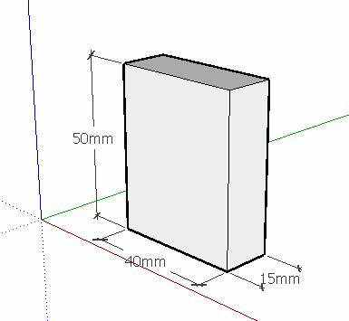
Draw the matchbox with the dimensions shown.
1. Use "Line" function only. Click on pencil or press "L". Start on the floor (in "top" view).
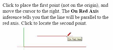
Look in the VCB (Value Control Box) and watch how the value changes as you move across the screen.
![]()
Type the value you want - in this case 40 (you do not have to write "mm")
Again you type the value in the VCB - 15 mm along green axis.
Finish the rectangle - observe and use "inference" function
Use ![]() tool or press and hold mouse wheel in order to
orbit your drawing (or click on
tool or press and hold mouse wheel in order to
orbit your drawing (or click on ![]() ISO)
ISO)
Draw vertical lines - type height in VCB
for first line and use "inference for second line Draw remaining lines using "inference" only
![]()
Finish box and add dimensions
using the ![]() tool
tool
Click on ![]() (ISO or 3D) view and the box should look as shown
here.
(ISO or 3D) view and the box should look as shown
here.
Click on save and your file will be saved with the right name and in the right place since you have already defined these parameters before you started drawing
2. Use "Line" function only. Click on pencil or press "L". Start on the wall (in "front" view).
Before you start drawing: Save file with new name -"Assignment 1 - front view"
Draw box again but notice that starting point is now the wall in front view - notice placement of axes.
 In order to make box stand on
floor, it is important to draw the first line on top of the red axes (floor
level)
In order to make box stand on
floor, it is important to draw the first line on top of the red axes (floor
level)
Use VCB ![]() to define length. Finish rectangle using "Line" function
to define length. Finish rectangle using "Line" function
Use ![]() tool or click on
tool or click on ![]() to
see 3D view (or use mouse wheel to orbit). Draw lines parallel to green axis as
indicated (15 mm long).
to
see 3D view (or use mouse wheel to orbit). Draw lines parallel to green axis as
indicated (15 mm long).
Draw remaining lines to finish box.
Try to switch between different views on the view toolbar in order to check out the function.
Remember to save file before closing
3. Finally, draw the same box, but start in "Right view".
Remember first to give your file a name and save it: "Assignment 1- right view"
This time we will use some other tools.
Pick tool rectangle ![]() and click on 1. Make sure you start on the
green axis.
and click on 1. Make sure you start on the
green axis.
Move curser slightly towards point 2 and watch info in VCB. Write 50;15 in VCB and press "ENTER"
You should now have a box like the one on the left.
 Use
Use ![]() tool or click on
tool or click on ![]() to
see 3D view (or use mouse wheel to orbit).
to
see 3D view (or use mouse wheel to orbit).
Use ![]() "Push/pull" tool to pull rectangle
"Push/pull" tool to pull rectangle
Watch VCB. Enter the value 40 and press "ENTER"
Try to switch between different views on the view toolbar in order to check out the function.
Apply dimensions ![]() - save and close.
- save and close.
Assignment 2
Use the tools and techniques you from assignment 1 and draw the model shown below.
Observe the following criteria:
The Model should be drawn in each of the two views: "Top" and "Front"
Remember to save the drawings. Always start a new drawing by saving it with an appropriate name.
This model is drawn in "Top" view
Assignment 3
Use the tools and techniques you from assignment 1 and draw the model shown below.
Observe the following criteria:
The Model should be drawn in each of the three views: "Top", "Front" and "Right"
Remember to save the drawings. Always start a new drawing by saving it with an appropriate name.
Start in "Top" view and draw a box as shown.
Use ![]() "Tape
measure" to offset "guides" as shown - see teachers illustration.
"Tape
measure" to offset "guides" as shown - see teachers illustration.
Draw lines on top of the dotted lines and continue drawing on your own...
You can erase dotted lines again using ![]() "eraser" tool
"eraser" tool
Remember to draw this model in "front" and "right" views also.
Save all views with appropriate name
Assignment 4
A hammer head with a rectangular hole for the handle
Use the tools and techniques you from assignment 1 and draw the model shown below.
Observe the following criteria:
 The Model should be
drawn in each of the three views: "Top", "Front" and "Right"
The Model should be
drawn in each of the three views: "Top", "Front" and "Right"
Remember to save the drawings. Always start a new drawing by saving it with an appropriate name.
Assignment 5
In this exercise you are presented with a "Front" view and a "Top" view only.
Based on this information you are requested to draw 3D model.
The Model should be drawn in each of the three views: "Top", "Front" and "Right"
Remember to save the drawings. Always start a new drawing by saving it with an appropriate name.
Assignment 6
Same procedure as in assignment 5.
The model should be drawn in each of the three views: "Top", "Front" and "Right"
Remember to save the drawings. Always start a new drawing by saving it with an appropriate name.
Assignment 7
The model should be drawn in each of the views: "Top", "Right"
Remember to save the drawings. Always start a new drawing by saving it with an appropriate name.
Assignment 8
The model should be drawn in the : "Top" view
Remember to save the drawings. Always start a new drawing by saving it with an appropriate name.
Tip: Setting off measurements used the ![]() "Tape
measure" tool
"Tape
measure" tool
Assignment 9
Before we start this assignment we will activate yet another tool which will help us to "look through" the model as we draw.
We will change our template as follows.
Open a new drawing
Click on "view"->"Toolbars"->Face Style"
A new toolbar is now activated and we will save the
file in C:\Program files\Google\SketchUP6\Templates.
Find the file you have already saved with your name, for example "Karsten top view".
Click on the file and when prompted to overwrite, say "Yes"
Click on "Window"->Preferences"->"Template"
Find your file on the list, click and the click "OK"
The new toolbar will now be active whenever you open a new drawing. Try to hover on top of the buttons to see functions.
Whenever we draw in SketchUp, a model can be drawn in many different ways. The method we will use here is not better than any other method, but it will help you understand some construction principles that may be applied when drawing complex shapes.
In many case it may be a good idea to construct the model "inside" a well known shape, like for example a box.
Analysing the plan and the elevation we find that maximum dimension for length, width and height (LxWxH) are: 70x50x50 mm.
So, start by drawing a box with these dimensions. Start in "Top" view. You will get a box like the one shown on the next page.
Now, click on your new tool X-ray and your box becomes transparent
We will now inset a "new floor" inside the box elevated 40 mm from the base.
Follow these steps to do so:
Orbit the box and select the floor by double clicking on it like this
Orbit back to previous view and activate ![]() "Move" tool
"Move" tool
Pick one of the corner of the selected floor and hold down "ctrl" key.
Now, move the floor upwards along blue axis - but do not click yet
write 40 in VCB and click
Your model now looks like this:
Press "space bar" and click somewhere outside the model in order to deactivate the selected new floor
By now we have got a main framework on which we can build our model. Next steps will include the setting out of "guides" according to our plan drawing (see previous assignment 3)
Activate the ![]() "Tape
measure" tool and set off the "guides" shown below. When doing so, it is very
important to observe that you follow the direction of the axis (red and green).
"Tape
measure" tool and set off the "guides" shown below. When doing so, it is very
important to observe that you follow the direction of the axis (red and green).
We start on the inserted floor, like this
We have now defined end point of lines in one of the "gables" of the
model and before we continue with more "guides" we will draw the "gable". Pick
the ![]() tool
and draw the 3 lines as shown in the next illustration:
tool
and draw the 3 lines as shown in the next illustration:
Before we continue, we will delete "guides"
Click on "Edit"->"Delete Guides"
We now repeat the same exercise setting off "guides" on top of the box as shown here:
Assisted by the newly defined end points we draw the other gable
Delete "guides" and draw the two lines completing the "roof" of the model.
We may now delete our inclosing box. Use the ![]() "Eraser" tool and remove the box bit by bit.
"Eraser" tool and remove the box bit by bit.
If you make a mistake you can always go back using the ![]() "Undo" tool
"Undo" tool
Orbiting the model makes it easier to see what you have to erase.
This is the result you get:
Try now to click on ![]() "X-ray" tool again and you will get the
following image:
"X-ray" tool again and you will get the
following image:
As you will notice, the model does not have any "coverings" on the sides.
Try to have a look at your model in "Right" view, and you may guess why. The sides consist of planes that are not coplanar (in the same plane. We can create 2 planes on either side, which are coplanar. Look at the next image:
Try connecting point 1 and 2 with a line (on both sides of the model), and see the effect.
You will notice that you have now created two independent coplanar faces on both sides of the model.
Save your drawing
Assignment 10
This model can also be drawn inside a box, but there are many other ways of drawing it!!
|
