DC Motor Speed Modeling in Simulink
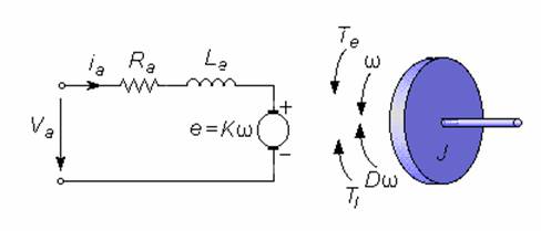
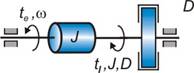
A common actuator in control systems is the DC motor. It directly provides rotary motion and, coupled with wheels or drums and cables, can provide transitional motion. The electric circuit of the armature and the free body diagram of the rotor are shown in the following figure:

 Figure
1.
Figure
1. 
For this example, we will assume the following values for the physical parameters.
(Date preluate din Babuska si CMT-Modelul cu aceste date Este complet irelevant pentru ilustrarea comportarii mcc deoarece curentul, respectiv cuplul prezinta variatii specifice unui element de ord. 1 nu cum este in practica, adica de element de ord. 2 (cu zero suplimentar) aperiodic sau oscilant).
The motor torque ![]() , is related to the armature current,
, is related to the armature current, ![]() , by a constant factor
, by a constant factor ![]() . The back emf
. The back emf ![]() , is related to the rotational velocity by the following
equations:
, is related to the rotational velocity by the following
equations:
![]() ,
,
In SI units (which we will use), ![]() (torque or armature
constant) is equal to
(torque or armature
constant) is equal to ![]() (electromotive force constant).
(electromotive force constant).
The behaviour of the electric circuit armature is described by Kirchhoff voltage law:
![]() .
(1)
.
(1)
The free-body diagram for the rotor, shown in
Fig. 1, defines the positive direction and shows the three applied torques, ![]() (motor torque),
(motor torque), ![]() (load torque) and
(load torque) and ![]() (damping torque).
Application of
(damping torque).
Application of
![]() . (2)
. (2)
The simulation in SIMULINK can be realised in three different ways.
By using, for equation (1) modelling, electrical elements from Power System Blockset (See SIMULINK Library). Equation (2) is usually modelled with an integrator according to relation:
![]() (3)
(3)
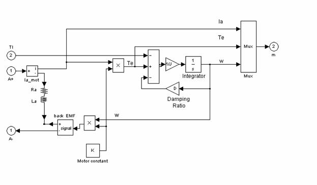
Figure 2
Block diagram shown in Fig. 2 is implemented in SIMULINK file undermaskdcmotormodel1.mdl . An example for simulation is contained in SIMULINK file dcmotormodel1.mdl (see Fig. 3).
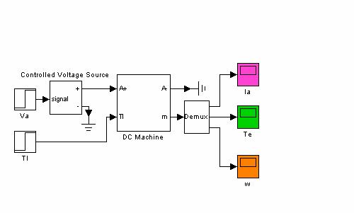
Figure 3.
Using integrators for both equations (1) and (2). Equation (1) will be write in the same form like (3):
![]() . (4)
. (4)

Figure 4.
Block diagram shown in Fig. 4 is implemented in SIMULINK file undermaskdcmotormodel2.mdl . An example for simulation is contained in SIMULINK file dcmotormodel2.mdl (see Fig. 5).
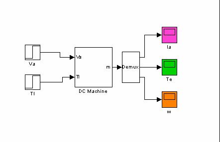
Figure 5.
Using Laplace transforms for the equations (1) and (2) written according to relations:
![]() , (5)
, (5)
![]() . (6)
. (6)
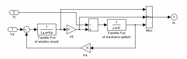
Figure 6.
Block diagram shown in Fig. 6 is implemented in SIMULINK file undermaskdcmotormodel3.mdl . An example for simulation is contained in SIMULINK file dcmotormodel3.mdl (see Fig. 7).
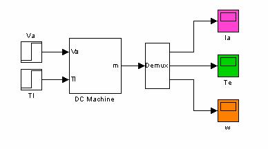
Figure 7.
|
