PROCEDURA DE TESTARE FUNCTIONALA & DE PROGRAMARE A CARDULUI IDR-140M CMS 4´
Echipamentele necesare pentru testare, sunt:
|
|
Sursa de alimentare\ -48V/5A |
|
|
Multimetru (pentru masurarea tensiunilor +DC) |
|
|
Osciloscop digital care are memorat shape of the 2 Mbit/G.703/75&120 Ohm pulse |
|
|
Frecventmetru pentru masurarea semnalelor |
|
|
BERmetru pentru rata de 2 Mbit cu interfata de 75 & 120 Ohm |
|
|
DataCom Analyser cu interfata V.24 (RS232) |
|
|
Un PC, cu caracteristici minime: Pe II 350/64 MB RAM/2,5 GB HDD |
|
|
Un cablu serial pentru conectarea la PC |
|
|
Un cablu pentru programarea JTAG |
|
|
O placa externa de distributie cu cabluri |
|
|
Un terminator de 75 Ohm |
|
|
Unterminator de 120 Ohm |
|
|
Un modul pentru testul extern I/O |
|
|
Un rack de referinta pentru teste.Structura rack-ului este prezentata in figura 1. |
Figura . Rack de referinta folosit pentru teste
Urmatoarele programe software trebie sa fie instalat pe PC:
Se verifica daca strapurile si jumperii sunt in pozitiile corecte. Locatia strapurilor si a jumperilor pe card sunt prezentate in fiugura urmatoare:
Figure

Figure
De asemenea, se verifica daca jumperii din Tabelul 1 sunt in pozitie corecta.
|
J1B |
DESCHIS |
|
J1H |
DESCHIS |
|
J2B |
DESCHIS |
|
J2H 151p157b |
DESCHIS |
|
J4B |
DESCHIS |
|
JM2 |
DESCHIS |
|
J5B |
DESCHIS |
|
JM3 |
DESCHIS |
|
J6B |
DESCHIS |
|
JM4 |
DESCHIS |
|
J7B |
DESCHIS |
|
JM5 |
DESCHIS |
|
J2 |
DESCHIS |
|
U1_J1 |
POZITIA 1-2 |
|
J3 |
DESCHIS |
|
JI1 |
DESCHIS |
|
J1F |
POZITIA 1-2 |
|
JI2 |
DESCHIS |
|
J1E |
INCHIS |
|
JI3 |
DESCHIS (75 Ohm) INCHIS (120 Ohm) |
|
J2E |
DESCHIS |
|
JI4 |
DESCHIS (75 Ohm) INCHIS (120 Ohm) |
|
J3E |
DESCHIS |
|
JI5 |
DESCHIS (75 Ohm) INCHIS (120 Ohm) |
|
J4E |
DESCHIS |
|
JI6 |
DESCHIS (75 Ohm) INCHIS (120 Ohm) |
|
J4 |
DESCHIS |
|
JI7 |
DESCHIS (75 Ohm) INCHIS (120 Ohm) |
|
J5 |
DESCHIS |
|
JI8 |
DESCHIS (75 Ohm) INCHIS (120 Ohm) |
|
J6 |
DESCHIS |
|
JI9 |
DESCHIS (75 Ohm) INCHIS (120 Ohm) |
|
J7 |
DESCHIS |
|
JI10 |
DESCHIS (75 Ohm) INCHIS (120 Ohm) |
Tabelul 1
Pentru aceasta procedura se va folosi cablul de programare JTAG si programul software WebPack.
Se efectueaza urmatorii pasi:
|
TDO |
Pin 3 |
|
TDI |
Pin 5 |
|
TMS |
Pin 7 |
|
TCK |
Pin 9 |
|
VCC |
Pin 11 |
|
GND |
Pin 2, Pin 4, Pin 6, Pin 8, Pin 10, Pin 12, Pin 14 |
|
No Connect |
Pin 1, Pin 13 |
Tabelul 2
0xFF
Visual Inspection
( Spinning "/" end-> Hello !!!)
Intel Flash Memory
0x00
0x01
Atmel Flash Memory
0x00
0x01
I/O (Buzzer, CPU Led, ALM Led)
0xFF
Acoustic / Visual Inspection
MODULE Presence
0x00
0x0F
0x0F = 0000 1 1 1 1
4 I/O EOW
0xFF
Visual Inspection
RTC
0x00
0x01
NMS1 (serial 1)
0x00
0x01
NMS2 (serial 2)
0x00
0x02
Buttons (Enter, Exit, Up, Down)
0xFF
Visual Inspection
Framer (SPI)
0x00
0x01
ODU1 & ODU2
0x00
0x01 & 0x02
Figure
For tests 1, 6 and 10 require the Test Operator Intervention in order to complete them.
During test 1, the 1´8 LCD will spin the following characters " / - | \ " and will complete the test by displaying "HELLO!!!". For the successful completion of the test, all the pixels on the display matrix should flash ON and OFF.
For test 6, the use of the external I/O board is required. The board consists of 4 LEDs for output indication, and 4 switches for selecting input alarm activation commands. When starting the test, the 4 LEDs will turn ON and OFF one at a time, so it can test the 4 output lines. After the output test is completed, the test operator should test the 4 input lines by switching the 4 switches ON and OFF one at a time and observing the 1´8 LCD for switch indication. The test is completed successfully when all 4 LEDs turn ON and OFF and when the user switches ON and OFF the 4 switches we get a confirmation of switch activity on the display.
Figure . External I/O board
In test 10 when the respective button is held pressed (Enter, Exit, Up, Down), then on the 1´8 LCD the respective word (Enter, Exit, Up, Down) should be displayed. The test operator should verify whether the button has been pressed and then released in order to successfully complete the test.
In order for Test 6 to continue, the operator needs to PRESS ENTER
In order for Test 10 to continue, the operator needs to PRESS SIMULTANIOUS ENTER & EXIT.
When testing has finished operator MUST OPEN Jumper J1E.
PANA AICI AM DE TRADUS
For this procedure we must connect the serial cable, first to the serial port of the PC and then to the NMS 1 port to the CMS card on the rack. The test procedure is split into the following steps.
|
Bit Rate |
|
2,048 Mbit/s (Unframed) |
|
Line Code |
|
HDB3 |
|
Line Impedance |
|
75 Ohm (unbalanced) |
|
Test Pattern |
|
PRBS-15 |
|
Tx Clock Source |
|
Internal |
|
Rx Clock Source |
|
Recovered from data (if required) |
|
Jitter |
|
OFF |
|
Clock |
|
Calibrated |
Then connect the 4X2 75-Ohm system as follows:
Figure
If the system under test is a 4X2 120-Ohm system, the connection should be as follows:
Figure .
The connections within the D25 Female connector and with the BER tester in the case of the 120-Ohm system, are shown in the following table:
|
CONNECTIONS ON THE D25 CONNECTOR AND TO THE BER TESTER |
||||||||||||||
|
BER Tester Out (+) |
|
|
|
|
|
|
|
|
|
|
|
|
|
BER Tester In (+) |
|
BER Tester Out (-) |
|
|
|
|
|
|
|
|
|
|
|
|
|
BER Tester In (-) |
|
BER Tester GND |
|
|
|
|
|
|
|
|
|
|
|
|
|
BER Tester GND |
The pin assignment on the D25 Male connector on the front panel of the system, is:
|
|
GND |
|
|
|
OUT-4P |
Positive OUT 4 |
|
|
OUT-4N |
Negative OUT 4 |
|
|
IN-4P |
Positive IN 4 |
|
|
IN-4N |
Negative IN 4 |
|
|
GND |
|
|
|
GND |
|
|
|
OUT-3P |
Positive OUT 3 |
|
|
OUT-3N |
Negative OUT 3 |
|
|
IN-3P |
Positive IN 3 |
|
|
IN-3N |
Negative IN 3 |
|
|
GND |
|
|
|
GND |
|
|
|
OUT-2P |
Positive OUT 2 |
|
|
OUT-2N |
Negative OUT 2 |
|
|
IN-2P |
Positive IN 2 |
|
|
IN-2N |
Negative IN 2 |
|
|
GND |
|
|
|
GND |
|
|
|
OUT-1P |
Positive OUT 1 |
|
|
OUT-1N |
Negative OUT 1 |
|
|
IN-1P |
Positive IN 1 |
|
|
IN-1N |
Negative IN 1 |
|
|
GND |
|
|
|
GND |
|
|
|
|
|
After all the connections as shown above have been made, the green led must remain OFF and the red leds must be switched OFF.
At the BERmeter we must see NO ERRORS.
The BER Measurement takes place for about 1 min.
Change the Test Pattern on the BERmeter from PRBS-15 to pattern "1000". Then make the connections as shown in the following figures, depending on whether the system under test is 75-Ohm or 120-Ohm. For the connection to the Oscilloscope we must use a 75-Ohm termination module. The shape of the pulse must already be stored in the memory of the Oscilloscope, and its characteristics are shown in the figure that follows.
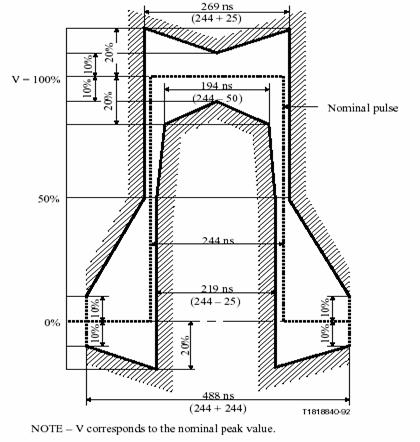
Figure
In the case of the 75-Ohm system, repeat the same procedure for all of 4 channels to verify that the mask pulse is according to G.703 specs. After finishing the test, change the test pattern back to PRBS-15.
Figure
In the case of the 120-Ohm system the test cable assembly, which connects the system with the BER tester, is shown in the following figure. Tests should be repeated for all the system tributaries. Note that the way the (+) or (-) inputs of each tributary is connected to the BER tester or to the 120-Ohm termination module, is not significant.
Figure .
Use the pin assignment on the D25 Male connector given earlier, in order to construct the test cable assembly, if not already constructed.
First of all we must make the following settings to the Datacom Analyser.
|
Interface: |
V.24 [DTE] [ASYNC] |
|
Tx Data Rate: |
19.2 KB/s |
|
Character Length: |
|
|
Stop Bits: |
|
|
Parity: |
None |
|
Test Pattern: |
PRBS-15 |
Before we start the procedure we must connect the serial cable, first to the serial port of the PC and then to the NMS1 port of the CMS. The test procedure is split into the following steps.
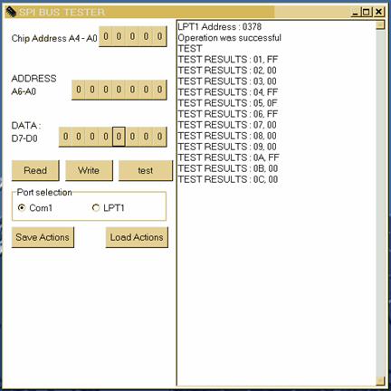
Run on the PC, the SPI Configurator Software. Select COM 1 (or COM 2) from Port Selection menu. Press the LOAD ACTIONS button, click OPEN and from the browser window select the C:/CIU/CMS_Mux4x2/Submux_mux4x2.txt file.
2.) Press the LOAD ACTIONS button, click OPEN and from the browser window select the
C:/CIU/CMS_Mux4x2/loop_framer_a_b.txt file.
3.) Then connect the External Distribution Board, first to the AUX connector of the CMS card and then the D-type connector (D9 or D25) to the Datacom Analyser. The connections are shown in the following figure.
Figure .
To the Datacom Analyser we must see NO ERRORS.
The BER Measurement takes place for about 1 min.
1.) Press the LOAD ACTIONS button, click OPEN and from the browser window select the
C:/CIU/CMS_Mux4x2/submux_tx_path.txt file. We must read in SPI Configurator window the following value [14].
2.)Press the LOAD ACTIONS button, click OPEN and from the browser window select the
C:/CIU/CMS_Mux4x2/submux_rx_path.txt file. We must read in SPI Configurator window the following value [00].
3.) Press the LOAD ACTIONS button, click OPEN and from the browser window select the
C:/CIU/CMS_Mux4x2/submux_switch_path.txt file. When the file loads, the Datacom Analyser may have errors for a while. We reset the instrument and after that we must have the indication NO ERRORS
4.) Press the LOAD ACTIONS button, click OPEN and from the browser window select the
C:/CIU/CMS_Mux4x2/submux_tx_path.txt file. We must read in SPI Configurator window the following value [98].
5.) Press the LOAD ACTIONS button, click OPEN and from the browser window select the
C:/CIU/CMS/submux_rx_path.txt file. We must read in SPI Configurator window the following value [02].
|
