INDUSTRIAL EQUIPMENTS
SEMESTER PROJECT
OPTICAL FIBERS
![]() Definition
Definition
![]() History
History
![]() Properties
Properties
![]() Structure
Structure
![]() Advantages
Advantages
![]() Fabrication
Fabrication
![]() Equipments
Equipments
![]() And other theoretical aspects
And other theoretical aspects
Militaru Letitia Ioana
Group 1235 E
DEFINITION
Fiber optics uses light to send information (data). More formally, fiber optics is the branch of optical technology concerned with the transmission of radiant power (light energy) through fibers.
HISTORY OF FIBER OPTIC TECHNOLOGY
People have used light to transmit information for hundreds of years. However, it was not until the 1960s, with the invention of the laser, that widespread interest in optical (light) systems for data communications began. The invention of the laser prompted researchers to study the potential of fiber optics for data communications, sensing, and other applications. Laser systems could send a much larger amount of data than telephone, microwave, and other electrical systems. The first experiment with the laser involved letting the laser beam transmit freely through the air. Researchers also conducted experiments letting the laser beam transmit through different types of waveguides. Glass fibers, gas-filled pipes, and tubes with focusing lenses are examples of optical waveguides. Glass fibers soon became the preferred medium for fiber optic research.
Initially, the very large losses in the optical fibers prevented coaxial cables from being replaced. Loss is the decrease in the amount of light reaching the end of the fiber. Early fibers had losses around 1,000 dB/km making them impractical for communications use. In 1969, several scientists concluded that impurities in the fiber material caused the signal loss in optical fibers. The basic fiber material did not prevent the light signal from reaching the end of the fiber. These researchers believed it was possible to reduce the losses in optical fibers by removing the impurities. By removing the impurities, construction of low-loss optical fibers was possible.
In 1970, Corning Glass Works made a multimode fiber with losses under 20 dB/km.
This same company, in 1972, made a high silica-core multimode optical fiber with 4dB/km minimum attenuation (loss). Currently, multimode fibers can have losses as low as 0.5 dB/km at wavelengths around 1300 nm. Single mode fibers are available with losses lower than 0.25 dB/km at wavelengths around 1500 nm.
Developments in semiconductor technology, which provided the necessary light sources and detectors, furthered the development of fiber optics. Conventional light sources, such as lamps or lasers, were not easily used in fiber optic systems. These light sources tended to be too large and required lens systems to launch light into the fiber. In 1971, Bell Laboratories developed a small area light-emitting diode (LED). This light source was suitable for low-loss coupling to optical fibers. Researchers could then perform source-to-fiber jointing easily and repeatedly. Early semiconductor sources had operating lifetimes of only a few hours. However, by 1973, projected lifetimes of lasers advanced from a few hours to greater than 1,000 hours. By 1977, projected lifetimes of lasers advanced to greater than 7,000 hours. By 1979, these devices were available with projected lifetimes of more than 100,000 hours.
In addition, researchers also continued to develop new fiber optic parts. The types of new parts developed included low-loss fibers and fiber cables, splices, and connectors. These parts permitted demonstration and research on complete fiber optic systems.
Advances in fiber optics have permitted the introduction of fiber optics into present applications. These applications are mostly in the telephone long-haul systems, but are growing to include cable television, computer networks, video systems, and data links. Research should increase system performance and provide solutions to existing problems in conventional applications. The impressive results from early research show there are many advantages offered by fiber optic systems.
ADVANTAGES AND DISADVANTAGES OF FIBER OPTICS
Fiber optic systems have many attractive features that are superior to electrical systems. These include improved system performance, immunity to electrical noise, signal security, and improved safety and electrical isolation.
Other advantages include reduced size and weight, environmental protection, and overall system economy. Table 1-1 details the main advantages of fiber optic systems.
Despite the many advantages of fiber optic systems, there are some disadvantages.
Because of the relative newness of the technology, fiber optic components are expensive. Fiber optic transmitters and receivers are still relatively expensive compared to electrical interfaces. The lack of standardization in the industry has also limited the acceptance of fiber optics. Many industries are more comfortable with the use of electrical systems and are reluctant to switch to fiber optics. However, industry researchers are eliminating these disadvantages. Standards committees are addressing fiber optic part and test standardization.
The cost to install fiber optic systems is falling because of an increase in the use of fiber optic technology. Published articles, conferences, and lectures on fiber optics have begun to educate managers and technicians. As the technology matures, the use of fiber optics will increase because of its many advantages over electrical systems
PROPAGATION OF LIGHT
The exact nature of light is not fully understood, although people have been studying the subject for many centuries. In the 1700s and before, experiments seemed to indicate that light was composed of particles. In the early 1800s, a physicist Thomas Young showed that light exhibited wave characteristics.
Further experiments by other physicists
culminated in James Clerk (pronounced
The advent of quantum physics successfully explained the photoelectric effect in terms of fundamental particles of energy called quanta. Quanta are known as photons when referring to light energy.
Today, when studying light that consists of many photons, as in propagation, that light behaves as a continuum - an electromagnetic wave. On the other hand, when studying the interaction of light with semiconductors, as in sources and detectors, the quantum physics approach is taken. The wave versus particle dilemma can be addressed in a more formal way, but that is beyond the scope of this text. It suffices to say that much has been reconciled between the two using quantum physics. In this manual, we use both the electromagnetic wave and photon concepts, each in the places where it best matches the phenomenon we are studying.
The electromagnetic energy of light is a form of electromagnetic radiation. Light and similar forms of radiation are made up of moving electric and magnetic forces. A simple example of motion similar to these radiation waves can be made by dropping a pebble into a pool of water. In this example, the water is not actually being moved by the outward motion of the wave, but rather by the up-and-down motion of the water. The up-and-down motion is transverse, or at right angles, to the outward motion of the waves. This type of wave motion is called transverse-wave motion. The transverse waves spread out in expanding circles until they reach the edge of the pool, in much the same manner as the transverse waves of light spread from the sun. However, the waves in the pool are very slow and clumsy in comparison with light, which travels approximately 186,000 miles per second.
Light radiates from its source in all directions until it is absorbed or diverted by some substance The lines drawn from the light source (a light bulb in this instance) to any point on one of the transverse waves indicate the direction that the wavefronts are moving. These lines, are called light rays.
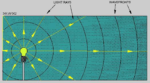
Although single rays of light typically do not exist, light rays shown in illustrations are a convenient method used to show the direction in which light is traveling at any point. A ray of light can be illustrated as a straight line.
PROPERTIES OF LIGHT
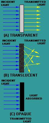
When light waves, which travel in straight lines, encounter any substance, they are either reflected, absorbed, transmitted, or refracted. This is illustrated forwards . Those substances that transmit almost all the light waves falling upon them are said to be transparent. A transparent substance is one through which you can see clearly.
Clear glass is transparent because it transmits light rays without diffusing them .There is no substance known that is perfectly transparent, but many substances are nearly so. Substances through which some light rays can pass, but through which objects cannot be seen clearly because the rays are diffused, are called translucent The frosted glass of a light bulb and a piece of oiled paper are examples of translucent materials. Those substances that are unable to transmit any light rays are called opaque. Opaque substances either reflect or absorb all the light rays that fall upon them.
Figure - Light waves reflected, absorbed, and transmitted.
Figure. - Substances: A. Transparent; B. Translucent; and C. Opaque.
All substances that are not light sources are visible only because they reflect all or some part of the light reaching them from some luminous source.
Examples of luminous sources include the sun, a gas flame, and an electric light filament, because they are sources of light energy. If light is neither transmitted nor reflected, it is absorbed or taken up by the medium. When light strikes a substance, some absorption and some reflection always take place. No substance completely transmits, reflects, or absorbs all the light rays that reach its surface.
BASIC STRUCTURE OF AN OPTICAL FIBER
The basic structure of an optical fiber consists of three parts; the core, the cladding, and the coating or buffer. The basic structure of an optical fiber is shown in figure The core is a cylindrical rod of dielectric material. Dielectric material conducts no electricity. Light propagates mainly along the core of the fiber. The core is generally made of glass. The core is described as having a radius of (a) and an index of refraction n1. The core is surrounded by a layer of material called the cladding. Even though light will propagate along the fiber core without the layer of cladding material, the cladding does perform some necessary functions.
Figure - Basic structure of an optical fiber.
The cladding layer is made of a dielectric material with an index of refraction n2. The index of refraction of the cladding material is less than that of the core material. The cladding is generally made of glass or plastic. The cladding performs the following functions:
Reduces loss of light from the core into the surrounding air
For extra protection, the cladding is enclosed in an additional layer called the coating or buffer. The coating or buffer is a layer of material used to protect an optical fiber from physical damage. The material used for a buffer is a type of plastic.
The buffer is elastic in nature and prevents abrasions. The buffer also prevents the optical fiber from scattering losses caused by microbends. Microbends occur when an optical fiber is placed on a rough and distorted surface. Microbends are discussed later in this chapter.
PROPAGATION OF LIGHT ALONG A FIBER
The concept of light propagation, the transmission of light along an optical fiber, can be described by two theories. According to the first theory, light is described as a simple ray. This theory is the ray theory, or geometrical optics, approach. The advantage of the ray approach is that you get a clearer picture of the propagation of light along a fiber. The ray theory is used to approximate the light acceptance and guiding properties of optical fibers. According to the second theory, light is described as an electromagnetic wave. This theory is the mode theory, or wave representation, approach. The mode theory describes the behavior of light within an optical fiber. The mode theory is useful in describing the optical fiber properties of absorption, attenuation, and dispersion. These fiber properties are discussed later in this chapter.
Ray Theory
Two types of rays can propagate along an optical fiber. The first type is called meridional rays. Meridional rays are rays that pass through the axis of the optical fiber. Meridional rays are used to illustrate the basic transmission properties of optical fibers.
The second type is called skew rays. Skew rays are rays that travel through an optical fiber without passing through its axis.
MERIDIONAL RAYS. - Meridional rays can be classified as bound or unbound rays. Bound rays remain in the core and propagate along the axis of the fiber. Bound rays propagate through the fiber by total internal reflection. Unbound rays are refracted out of the fiber core. Figure 2-10 shows a possible path taken by bound and unbound rays in a step-index fiber. The core of the step-index fiber has an index of refraction n1. The cladding of a step-index has an index of refraction n2, that is lower than n1. Figure 2-10 assumes the core-cladding interface is perfect. However, imperfections at the core-cladding interface will cause part of the bound rays to be refracted out of the core into the cladding. The light rays refracted into the cladding will eventually escape from the fiber. In general, meridional rays follow the laws of reflection and refraction.
Figure - Bound and unbound rays in a step-index fiber.
It is known that bound rays propagate in fibers due to total internal reflection, but how do these light rays enter the fiber? Rays that enter the fiber must intersect the core-cladding interface at an angle greater than the critical angle (Θc). Only those rays that enter the fiber and strike the interface at these angles will propagate along the fiber.
How a light ray is launched into a fiber is shown in the figure The incident ray I1 enters the fiber at the angle Θa. I1 is refracted upon entering the fiber and is transmitted to the core-cladding interface. The ray then strikes the core-cladding interface at the critical angle (Θ c). I1 is totally reflected back into the core and continues to propagate along the fiber. The incident ray I2 enters the fiber at an angle greater than Θa. Again, I2 is refracted upon entering the fiber and is transmitted to the core-cladding interface. I2 strikes the core-cladding interface at an angle less than the critical angle (Θc). I2 is refracted into the cladding and is eventually lost. The light ray incident on the fiber core must be within the acceptance cone defined by the angle Θa shown in figure 2-12.
Angle Θa is defined as the acceptance angle. The acceptance angle (Θa) is the maximum angle to the axis of the fiber that light entering the fiber is propagated. The value of the angle of acceptance (Θa) depends on fiber properties and transmission conditions.
Figure - How a light ray enters an optical fiber.
Figure - Fiber acceptance angle.
The acceptance angle is related to the refractive indices of the core, cladding, and medium surrounding the fiber. This relationship is called the numerical aperture of the fiber. The numerical aperture (NA) is a measurement of the ability of an optical fiber to capture light. The NA is also used to define the acceptance cone of an optical fiber.
The figure illustrates the relationship between the acceptance angle and the refractive indices. The index of refraction of the fiber core is n1. The index of refraction of the fiber cladding is n2. The index of refraction of the surrounding medium is n0. By using Snell's law and basic trigonometric relationships, the NA of the fiber is given by:
![]()
Since the medium next to the fiber at the launching point is normally air, n0 is equal to 1.00. The NA is then simply equal to sin Θa.
The NA is a convenient way to measure the light-gathering ability of an optical fiber. It is used to measure source-to-fiber power-coupling efficiencies. A high NA indicates a high source-to-fiber coupling efficiency.
Source-to-fiber coupling efficiency is described in chapter 6. Typical values of NA range from 0.20 to 0.29 for glass fibers. Plastic fibers generally have a higher NA. An NA for plastic fibers can be higher than 0.50.
In addition, the NA is commonly used to specify multimode fibers.
However, for small core diameters, such as in single mode fibers, the ray theory breaks down. Ray theory describes only the direction a plane wave takes in a fiber. Ray theory eliminates any properties of the plane wave that interfere with the transmission of light along a fiber. In reality, plane waves interfere with each other. Therefore, only certain types of rays are able to propagate in an optical fiber. Optical fibers can support only a specific number of guided modes. In small core fibers, the number of modes supported is one or only a few modes. Mode theory is used to describe the types of plane waves able to propagate along an optical fiber.
SKEW RAYS. - Skew rays propagate without passing through the center axis of the fiber.
The acceptance angle for skew rays is larger than the acceptance angle of meridional rays. This condition explains why skew rays outnumber meridional rays. Skew rays are often used in the calculation of light acceptance in an optical fiber. The addition of skew rays increases the amount of light capacity of a fiber. In large NA fibers, the increase may be significant.
Figure. - Skew ray propagation: A. Angled view; B. Front view.
The addition of skew rays also increases the amount of loss in a fiber. Skew rays tend to propagate near the edge of the fiber core. A large portion of the number of skew rays that are trapped in the fiber core are considered to be leaky rays. Leaky rays are predicted to be totally reflected at the core-cladding boundary. However, these rays are partially refracted because of the curved nature of the fiber boundary. Mode theory is also used to describe this type of leaky ray loss.
OPTICAL FIBER TYPES
Optical fibers are characterized by their structure and by their properties of transmission. Basically, optical fibers are classified into two types. The first type is single mode fibers. The second type is multimode fibers. As each name implies, optical fibers are classified by the number of modes that propagate along the fiber. As previously explained, the structure of the fiber can permit or restrict modes from propagating in a fiber. The basic structural difference is the core size. Single mode fibers are manufactured with the same materials as multimode fibers. Single mode fibers are also manufactured by following the same fabrication process as multimode fibers.
Single Mode Fibers
The core size of single mode fibers is small. The core size (diameter) is typically around 8 to 10 micrometers (μm). A fiber core of this size allows only the fundamental or lowest order mode to propagate around a 1300 nanometer (nm) wavelength. Single mode fibers propagate only one mode, because the core size approaches the operational wavelength (λ). The value of the normalized frequency parameter (V) relates core size with mode propagation.
In single mode fibers, V is less than or equal to 2.405. When V ≤ 2.405, single mode fibers propagate the fundamental mode down the fiber core, while high-order modes are lost in the cladding. For low V values (≤1.0), most of the power is propagated in the cladding material. Power transmitted by the cladding is easily lost at fiber bends. The value of V should remain near the 2.405 level.
Single mode fibers have a lower signal loss and a higher information capacity (bandwidth) than multimode fibers. Single mode fibers are capable of transferring higher amounts of data due to low fiber dispersion. Basically, dispersion is the spreading of light as light propagates along a fiber. Dispersion mechanisms in single mode fibers are discussed in more detail later in this chapter. Signal loss depends on the operational wavelength (λ). In single mode fibers, the wavelength can increase or decrease the losses caused by fiber bending. Single mode fibers operating at wavelengths larger than the cutoff wavelength lose more power at fiber bends. They lose power because light radiates into the cladding, which is lost at fiber bends. In general, single mode fibers are considered to be low-loss fibers, which increase system bandwidth and length.
Multimode Fibers
As their name implies, multimode fibers propagate more than one mode. Multimode fibers can propagate over 100 modes. The number of modes propagated depends on the core size and numerical aperture (NA). As the core size and
NA increase, the number of modes increases. Typical values of fiber core size and NA are 50 to 100 μm and 0.20 to 0.29, respectively.
A large core size and a higher NA have several advantages. Light is launched into a multimode fiber with more ease. The higher NA and the larger core size make it easier to make fiber connections. During fiber splicing, core-to-core alignment becomes less critical. Another advantage is that multimode fibers permit the use of light-emitting diodes (LEDs). Single mode fibers typically must use laser diodes. LEDs are cheaper, less complex, and last longer. LEDs are preferred for most applications.
Multimode fibers also have some disadvantages. As the number of modes increases, the effect of modal dispersion increases. Modal dispersion (intermodal dispersion) means that modes arrive at the fiber end at slightly different times. This time difference causes the light pulse to spread. Modal dispersion affects system bandwidth. Fiber manufacturers adjust the core diameter, NA, and index profile properties of multimode fibers to maximize system bandwidth.
PROPERTIES OF OPTICAL FIBER TRANSMISSION
The principles behind the transfer of light along an optical fiber were discussed earlier in this chapter. You learned that propagation of light depended on the nature of light and the structure of the optical fiber. However, our discussion did not describe how optical fibers affect system performance.
In this case, system performance deals with signal loss and bandwidth.
Signal loss and system bandwidth describe the amount of data transmitted over a specified length of fiber. Many optical fiber properties increase signal loss and reduce system bandwidth. The most important properties that affect system performance are fiber attenuation and dispersion.
Attenuation reduces the amount of optical power transmitted by the fiber.. Once the power of an optical pulse is reduced to a point where the receiver is unable to detect the pulse, an error occurs. Attenuation is mainly a result of light absorption, scattering, and bending losses. Dispersion spreads the optical pulse as it travels along the fiber. This spreading of the signal pulse reduces the system bandwidth or the information-carrying capacity of the fiber. Dispersion limits how fast information is transferred as shown in the figure below. An error occurs when the receiver is unable to distinguish between input pulses caused by the spreading of each pulse. The effects of attenuation and dispersion increase as the pulse travels the length of the fiber as shown in figure underneath.
Figure. - Fiber transmission properties.
Figure - Pulse spreading and power loss along an optical fiber.
In addition to fiber attenuation and dispersion, other optical fiber properties affect system performance. Fiber properties, such as modal noise, pulse broadening, and polarization, can reduce system performance.
Modal noise, pulse broadening, and polarization are too complex to discuss as introductory level material. However, you should be aware that attenuation and dispersion are not the only fiber properties that affect performance.
ATTENUATION
Attenuation in an optical fiber is caused by
absorption, scattering, and bending losses. Attenuation is the loss of optical power as light travels along
the fiber. Signal attenuation is defined as the ratio of optical input power (Pi)
to the optical output power (
Signal attenuation is a log relationship. Length (L) is expressed in kilometers. Therefore, the unit of attenuation is decibels/kilometer (dB/km). As previously stated, attenuation is caused by absorption, scattering, and bending losses. Each mechanism of loss is influenced by fiber-material properties and fiber structure. However, loss is also present at fiber connections. Fiber connector, splice, and coupler losses are discussed in chapter 4. The present discussion remains relative to optical fiber attenuation properties.
ABSORPTION
Absorption is a major cause of signal loss in an optical fiber. Absorption is defined as the portion of attenuation resulting from the conversion of optical power into another energy form, such as heat. Absorption in optical fibers is explained by three factors:
Imperfections in the atomic structure induce absorption by the presence of missing molecules or oxygen defects. Absorption is also induced by the diffusion of hydrogen molecules into the glass fiber. Since intrinsic and extrinsic material properties are the main cause of absorption, they are discussed further.
Intrinsic Absorption - Intrinsic absorption is caused by basic fiber-material properties. If an optical fiber were absolutely pure, with no imperfections or impurities, then all absorption would be intrinsic. Intrinsic absorption sets the minimal level of absorption.
In fiber optics, silica (pure glass) fibers are used predominately. Silica fibers are used because of their low intrinsic material absorption at the wavelengths of operation.
In silica glass, the wavelengths of operation range from 700 nanometers (nm) to 1600 nm. The figure shows the level of attenuation at the wavelengths of operation. This wavelength of operation is between two intrinsic absorption regions. The first region is the ultraviolet region (below 400-nm wavelength). The second region is the infrared region (above 2000-nm wavelength).
Figure. - Fiber losses.
Intrinsic absorption in the ultraviolet region is caused by electronic absorption bands. Basically, absorption occurs when a light particle (photon) interacts with an electron and excites it to a higher energy level. The tail of the ultraviolet absorption band is shown in figure 2-21.
The main cause of intrinsic absorption in the infrared region is the characteristic vibration frequency of atomic bonds. In silica glass, absorption is caused by the vibration of silicon-oxygen (Si-O) bonds. The interaction between the vibrating bond and the electromagnetic field of the optical signal causes intrinsic absorption. Light energy is transferred from the electromagnetic field to the bond. The tail of the infrared absorption band is shown in the figure.
Extrinsic Absorption - Extrinsic absorption is caused by impurities introduced into the fiber material. Trace metal impurities, such as iron, nickel, and chromium, are introduced into the fiber during fabrication. Extrinsic absorption is caused by the electronic transition of these metal ions from one energy level to another.
Extrinsic absorption also occurs when
hydroxyl ions (
These absorption peaks define three regions or windows of preferred operation. The first window is centered at 850 nm. The second window is centered at nm. The third window is centered at nm. Fiber optic systems operate at wavelengths defined by one of these windows.
The amount of water (
SCATTERING
Basically, scattering losses are caused by the interaction of light with density fluctuations within a fiber. Density changes are produced when optical fibers are manufactured.
During manufacturing, regions of higher and lower molecular density areas, relative to the average density of the fiber, are created. Light traveling through the fiber interacts with the density areas as shown in figure below. Light is then partially scattered in all directions.
Figure - Light scattering.
In commercial fibers operating between 700-nm and 1600-nm wavelength, the main source of loss is called Rayleigh scattering. Rayleigh scattering is the main loss mechanism between the ultraviolet and infrared regions as shown in the figure. Rayleigh scattering occurs when the size of the density fluctuation (fiber defect) is less than one-tenth of the operating wavelength of light. Loss caused by Rayleigh scattering is proportional to the fourth power of the wavelength (1/&lambda ). As the wavelength increases, the loss caused by Rayleigh scattering decreases.
If the size of the defect is greater than one-tenth of the wavelength of light, the scattering mechanism is called Mie scattering. Mie scattering, caused by these large defects in the fiber core, scatters light out of the fiber core. However, in commercial fibers, the effects of Mie scattering are insignificant. Optical fibers are manufactured with very few large defects.
BENDING LOSS
Bending the fiber also causes attenuation. Bending loss is classified according to the bend radius of curvature: microbend loss or macrobend loss.
Microbends are small microscopic bends of the fiber axis that occur mainly when a fiber is cabled. Macrobends are bends having a large radius of curvature relative to the fiber diameter. Microbend and macrobend losses are very important loss mechanisms. Fiber loss caused by microbending can still occur even if the fiber is cabled correctly. During installation, if fibers are bent too sharply, macrobend losses will occur.
Microbend losses are caused by small discontinuities or imperfections in the fiber. Uneven coating applications and improper cabling procedures increase microbend loss. External forces are also a source of microbends. An external force deforms the cabled jacket surrounding the fiber but causes only a small bend in the fiber. Microbends change the path that propagating modes take, as shown in figure. Microbend loss increases attenuation because low-order modes become coupled with high-order modes that are naturally lossy.
Figure. - Microbend loss.
Macrobend losses are observed when a fiber bend's radius of curvature is large compared to the fiber diameter.
These bends become a great source of loss when the radius of curvature is less than several centimeters. Light propagating at the inner side of the bend travels a shorter distance than that on the outer side. To maintain the phase of the light wave, the mode phase velocity must increase. When the fiber bend is less than some critical radius, the mode phase velocity must increase to a speed greater than the speed of light. However, it is impossible to exceed the speed of light. This condition causes some of the light within the fiber to be converted to high-order modes. These high-order modes are then lost or radiated out of the fiber.
Fiber sensitivity to bending losses can be reduced. If the refractive index of the core is increased, then fiber sensitivity decreases. Sensitivity also decreases as the diameter of the overall fiber increases. However, increases in the fiber core diameter increase fiber sensitivity. Fibers with larger core size propagate more modes. These additional modes tend to be more lossy.
DISPERSION
There are two different types of dispersion in optical fibers.
The types are intramodal and intermodal dispersion. Intramodal, or chromatic, dispersion occurs in all types of fibers. Intermodal, or modal, dispersion occurs only in multimode fibers. Each type of dispersion mechanism leads to pulse spreading. As a pulse spreads, energy is overlapped. This condition is shown in figure. The spreading of the optical pulse as it travels along the fiber limits the information capacity of the fiber.
Figure - Pulse overlap.

Intramodal Dispersion
Intramodal, or chromatic, dispersion depends primarily on fiber materials. There are two types of intramodal dispersion. The first type is material dispersion. The second type is waveguide dispersion.
Intramodal dispersion occurs because different colors of light travel through different materials and different waveguide structures at different speeds.
Material dispersion occurs because the spreading of a light pulse is dependent on the wavelengths' interaction with the refractive index of the fiber core. Different wavelengths travel at different speeds in the fiber material. Different wavelengths of a light pulse that enter a fiber at one time exit the fiber at different times. Material dispersion is a function of the source spectral width. The spectral width specifies the range of wavelengths that can propagate in the fiber. Material dispersion is less at longer wavelengths.
Waveguide dispersion occurs because the mode propagation constant (β) is a function of the size of the fiber's core relative to the wavelength of operation. Waveguide dispersion also occurs because light propagates differently in the core than in the cladding.
In multimode fibers, waveguide dispersion and material dispersion are basically separate properties. Multimode waveguide dispersion is generally small compared to material dispersion. Waveguide dispersion is usually neglected.
However, in single mode fibers, material and waveguide dispersion are interrelated.
The total dispersion present in single mode fibers may be minimized by trading material and waveguide properties depending on the wavelength of operation.
Intermodal Dispersion
Intermodal or modal dispersion causes the input light pulse to spread. The input light pulse is made up of a group of modes. As the modes propagate along the fiber, light energy distributed among the modes is delayed by different amounts. The pulse spreads because each mode propagates along the fiber at different speeds. Since modes travel in different directions, some modes travel longer distances. Modal dispersion occurs because each mode travels a different distance over the same time span, as shown in figure. The modes of a light pulse that enter the fiber at one time exit the fiber a different times. This condition causes the light pulse to spread. As the length of the fiber increases, modal dispersion increases.
Figure. - Distance traveled by each mode over the same time span.
Modal dispersion is the dominant source of dispersion in multimode fibers. Modal dispersion does not exist in single mode fibers. Single mode fibers propagate only the fundamental mode. Therefore, single mode fibers exhibit the lowest amount of total dispersion. Single mode fibers also exhibit the highest possible bandwidth.
OPTICAL FIBERS
Classified optical fibers were either single mode or multimode fibers. Fibers are classified according to the number of modes that they can propagate. Single mode fibers can propagate only the fundamental mode. Multimode fibers can propagate hundreds of modes. However, the classification of an optical fiber depends on more than the number of modes that a fiber can propagate.
An optical fiber's refractive index profile and core size further distinguish single mode and multimode fibers. The refractive index profile describes the value of refractive index as a function of radial distance at any fiber diameter. Fiber refractive index profiles classify single mode and multimode fibers as follows:
In a step-index fiber, the refractive index of the core is uniform and undergoes an abrupt change at the core-cladding boundary. Step-index fibers obtain their name from this abrupt change called the step change in refractive index. In graded-index fibers, the refractive index of the core varies gradually as a function of radial distance from the fiber center.
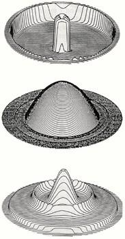
Single mode and multimode fibers can have a step-index or graded-index refractive index profile. The performance of multimode graded-index fibers is usually superior to multimode step-index fibers. However, each type of multimode fiber can improve system design and operation depending on the intended application. Performance advantages for single mode graded-index fibers compared to single mode step-index fibers are relatively small. Therefore, single mode fiber production is almost exclusively step-index. Figure 3-1 shows the refractive index profile for a multimode step-index fiber and a multimode graded-index fiber. Figure 3-1 also shows the refractive index profile for a single mode step-index fiber. Since light propagates differently in each fiber type, figure 3-1 shows the propagation of light along each fiber.
Figure 3-1. - The refractive index profiles and light propagation in multimode step-index, multimode graded-index, and single mode step-index fibers.
fiber core size and material composition can affect system performance. A small change in core size and material composition affects fiber transmission properties, such as attenuation and dispersion.
When selecting an optical fiber, the system designer decides which fiber core size and material composition is appropriate.
Standard core sizes for multimode step-index fibers are 50 μm and 100 μm. Standard core sizes for multimode graded-index fibers are 50 μm, 62.5 μm, 85 μm, and 100 μm. Standard core sizes for single mode fibers are between 8 μm and 10 μm. In most cases, the material used in the preparation of optical fibers is high-quality glass (SiO2).
This glass contains very low amounts of impurities, such as water or elements other than silica and oxygen. Using high-quality glass produces fibers with low losses. Small amounts of some elements other than silica and oxygen are added to the glass material to change its index of refraction. These elements are called material dopants. Silica doped with various materials forms the refractive index profile of the fiber core and material dopants are discussed in more detail later in this chapter. Glass is not the only material used in fabrication of optical fibers. Plastics are also used for core and cladding materials in some applications.
A particular optical fiber design can improve fiber optic system performance.
Each single mode or multimode, step-index or graded-index, glass or plastic, or large or small core fiber has an intended application. The system designer must choose an appropriate fiber design that optimizes system performance in his application.
FABRICATION OF OPTICAL FIBERS
Basically, fiber manufacturers use two methods to fabricate multimode and single mode glass fibers. One method is vapor phase oxidation, and the other method is direct-melt process. In vapor phase oxidation, gaseous metal halide compounds, dopant material, and oxygen are oxidized (burned) to form a white silica powder (SiO2). Manufacturers call SiO2 the soot.
Manufacturers deposit the soot on the surface of a glass substrate (mandrel) or inside a hollow tube by one of the following three methods:
The soot forms the core and cladding material of the preform. The refractive index of each layer of soot is changed by varying the amount of dopant material being oxidized. Figures 3-8, 3-9, and 3-10 illustrate the different vapor phase oxidation preform preparation methods.
Figure 3-8. - OVPO preform preparation.
Figure 3-9. - IVPO preform preparation.
Figure 3-10. - VAD preform preparation.
During vapor phase oxidation, the mandrel or tube continuously moves from side to side and rotates while soot particles are deposited on the surface. This process forms cylindrical layers of soot on the surface of the mandrel or inside the hollow tube. This deposited material is transformed into a solid glass preform by heating the porous material (without melting).
The solid preform is then drawn or pulled into an optical fiber by a process called fiber drawing.
The fiber drawing process begins by feeding the glass preform into the drawing furnace. The drawing furnace softens the end of the preform to the melting point. Manufacturers then pull the softened preform into a thin glass filament (glass fiber). To protect the bare fiber from contaminants, manufacturers add an acrylate coating in the draw process. The coating protects the bare fiber from contaminants such as atmospheric dust and water vapor. Figure 3-11 illustrates the process of drawing an optical fiber from the preform.
Figure 3-11. - Fiber drawing process.

In the direct-melt process, multicomponent glass rods form the fiber structure. Rods of multicomponent glass combine in a molten state to form the fiber core and cladding. The double-crucible method is the most common direct-melt process. The double-crucible method combines the molten rods into a single preform using two concentric crucibles.
Optical fibers are drawn from this molten glass using a similar fiber drawing process as in vapor phase oxidation. Figure 3-12 illustrates the double-crucible drawing process.
Figure 3-12. - Double-crucible fiber drawing process.
OPTICAL CABLES
Optical fibers have small cross sectional areas. Without protection, optical fibers are fragile and can be broken. The optical cable structure protects optical fibers from environmental damage. Cable structure includes buffers, strength members, and jackets. Many factors influence the design of fiber optic cables. The cable design relates to the cable's intended application.
Properly designed optical cables perform the following functions:
Protect optical fibers from damage and breakage during installation and over the fiber's lifetime.
Provide stable fiber transmission characteristics compared with uncabled fibers. Stable transmission includes stable operation in extreme climate conditions.
Maintain the physical integrity of the optical fiber by reducing the mechanical stresses placed on the fiber during installation and use. Static fatigue caused by tension, torsion, compression, and bending can reduce the lifetime of an optical fiber.
Navy applications require that fiber optic cables meet stringent design specifications. Fiber optic cables must be rugged to meet the optical, environmental, and mechanical performance requirements imposed by Navy systems. Critical system downtime caused by cable failure cannot be tolerated. However, in commercial applications, the requirements imposed on cable designs are not as stringent.
Each additional requirement imposed on the fiber optic cable design adds to its cost. Cost is always a main consideration of cable designers in commercial applications. Cost is also considered in Navy applications, but system reliability is the main goal.
FIBER BUFFERS
Coatings and buffers protect the optical fiber from breakage and loss caused by microbends. During the fiber drawing process, the addition of a primary coating protects the bare glass from abrasions and other surface contaminants. For additional protection, manufacturers add a layer of buffer material. The buffer material provides additional mechanical protection for the fiber and helps preserve the fiber's inherent strength.
Manufacturers use a variety of techniques to buffer optical fibers.
The types of fiber buffers include tight-buffered, loose-tube, and gel-filled loose-tube. Figure 3-13 shows each type of fiber buffer. The choice of buffering techniques depends on the intended application.
In large fiber count commercial applications, manufacturers use the loose-tube buffers. In commercial building and Navy applications, manufacturers use tight buffers.
Figure 3-13. - Tight-buffered, loose-tube, and gel-filled loose-tube buffer techniques.
CABLE DESIGNS
Manufacturers design fiber optic cables for specific applications. Is the cable buried underground or hung from telephone poles? Is the cable snaked through cableways, submerged in water, or just laid on the ground? Is the cable used in industrial, telecommunication, utility, or military applications? Each different application may require a slightly different cable design.
Agreement on standard cable designs is difficult. Cable design choices include jacket materials, water blocking techniques, and the number of fibers to place within the cable. The cable design chosen depends on the cable's intended application. There are presently many types of fiber optic cables. Some fiber optic cables are used in commercial applications, while others are used in military applications. Standard commercial cable designs will develop over time as fiber optic technology becomes more established. However, this chapter provides only a short discussion on cable designs considered for Navy applications.
Navy systems require that fiber optic cables meet stringent environmental conditions. The types of cable designs considered by the Navy include the optical fiber cable component (OFCC), stranded, and ribbon cable designs.
The cable must meet minimal levels of performance in safety (low smoke, low toxicity, low halogen content, etc.), durability (able to withstand shock, vibration, fluids, etc.), and optical performance. The cable must also be easy to install and repair. These factors greatly influence the design of the cables.
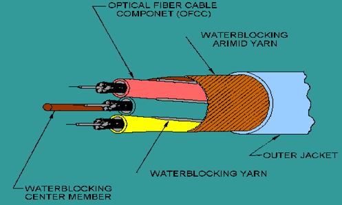
Optical Fiber Cable Component (OFCC) Cable
An OFCC cable consists of individual single fiber cables, called optical fiber cable components (OFCCs). OFCCs are a tight-buffered fiber surrounded by arimid yarn and a low-halogen outer jacket. The OFCC outer diameter is typically 2 millimeters (mm). The fiber is typically buffered with a polyester elastomer to a total diameter of 900 μm. Figure 3-14 illustrates the design of the OFCCs. The size of the OFCCs limits the amount of fibers contained within an OFCC cable. An OFCC cable generally contains less than 36 fibers (OFCCs). An OFCC cable of 0.5-inch cable outer diameter can accommodate about 12 fibers.
Figure 3-14. - The design of optical fiber cable components (OFCCs).
Figure 3-15 shows an isometric view of a four-fiber shipboard OFCC cable. In this multifiber cable design, the OFCCs surround a flexible central member in a helical manner. The central member may add to cable strength or only support the OFCCs. For additional protection, two layers of arimid yarn strength members encase the OFCC units. These strength members are stranded in opposing lays to minimize microbending of the fibers. The arimid yarn strength members may be treated with polymers that are water absorbing, blocking, and sealing. This treatment eliminates the need for additional water blocking protection. Finally, a low-halogen, flame-resistant outer jacket is extruded over the strength members.
Figure 3-15. - An isometric view of a four-fiber shipboard OFCC cable.
OFCC cables are easy to handle because each cable contains its own subcable, the OFCC. These OFCC subcables make it easy to reconfigure systems and handle individual fibers. Rugged OFCC cable design permits cable use in harsh environments, including Navy applications. OFCC-type cable is recommended for use in low-density (less than 24 fibers) Navy applications. OFCC-type cable is also being evaluated for use in Navy applications with fiber counts up to 36 fibers.
Stranded Cable A stranded cable is a fiber optic cable consisting of buffered fibers stranded down the center of the cable surrounded by strength members and a protective jacket. Figure 3-16 shows a cross-sectional view of the stranded cable. The fiber is typically buffered with a polyester elastomer to a total diameter of 900 μm. The recommended use of stranded cables is in medium-density (24 to 72 fibers) Navy applications. However, this recommendation is preliminary. Further test and evaluation of prototype stranded cable designs is continuing. Final approval of the stranded cable will occur only after prototype cables have passed all tests.
Figure 3-16. - Stranded cable design.
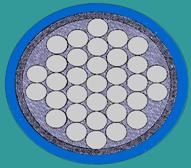
Stranded cable designs increase fiber counts without greatly increasing cable size. Stranded cables are used when fiber counts exceed the limits of OFCC-type cables. For example, the stranded cable design can accommodate about 48 fibers in a O.5-inch cable. The OFCC cable design can accommodate around 12 fibers. The individual fiber is not protected as well in the stranded design as in the OFCC design. For this reason more care is required in handling the individual fibers in the stranded design. The primary problem of the stranded cable design is in meeting the waterblocking requirements. Once manufacturers correct this design problem, the Navy expects that the stranded cable design will meet Navy performance requirements.
Ribbon Cable
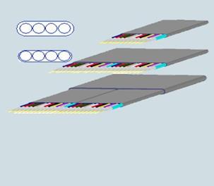
A ribbon cable consists of optical fiber ribbons stranded down the center of the cable surrounded by a protective tube, strength members, and an outer jacket. The fiber optic ribbon consists of multiple-coated, 250 μm diameter fibers sandwiched in a plastic material. Figure 3-17 shows a cross-sectional view of a 12-fiber ribbon. Cable manufacturers stack these ribbons to form a rectangular cross-sectional array of fibers. Stacked ribbons are the basic building blocks of the ribbon cable. Figure 3-18 illustrates this cross-sectional array of ribbons. Manufacturers introduce a controlled twist to the stacked ribbons to minimize fiber stress when the cable is bent. An inner plastic tube, strength members, and an outer protective jacket surround the stacked ribbons, providing environmental protection.
Figure 3-17. - Cross section of a fiber optic ribbon.
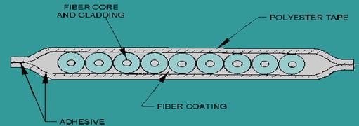
Figure 3-18. - Ribbon cable cross-sectional array of fibers.
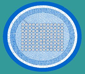
The ribbon cable design has the highest fiber capacity. Ribbon cables can hold 204 fibers in a 0.5-inch cable. However, ribbon cables have worse bend performance than OFCC and stranded cables. Ribbon cables also have the poorest waterblocking capabilities of the three cable designs. The bend performance is expected to worsen if manufacturers add appropriate compounds to increase waterblocking capabilities.
Ribbon cables are also hard to handle. Individual fibers are highly susceptible to damage when separated from the ribbon. This susceptibility to fiber damage during fiber breakout makes it necessary to perform multifiber connections. Multifiber connections can introduce single points of failure in multiple systems. The use of multifiber terminations also introduces maintenance, reconfiguration, and repair problems. Currently, the Navy does not recommend the use of ribbon cables in shipboard systems.
FIBER OPTIC CONNECTORS
A fiber optic connector is a demateable device that permits the coupling of optical power between two optical fibers or two groups of fibers. Designing a device that allows for repeated fiber coupling without significant loss of light is difficult. Fiber optic connectors must maintain fiber alignment and provide repeatable loss measurements during numerous connections. Fiber optic connectors should be easy to assemble (in a laboratory or field environment) and should be cost effective. They should also be reliable. Fiber optic connections using connectors should be insensitive to environmental conditions, such as temperature, dust, and moisture. Fiber optic connector designs attempt to optimize connector performance by meeting each of these conditions.
Fiber optic connector coupling loss results from the same loss mechanisms described earlier in this chapter. Coupling loss results from poor fiber alignment and end preparation (extrinsic losses), fiber mismatches (intrinsic loss), and Fresnel reflection. The total amount of insertion loss for fiber optic connectors should remain below 1 dB. Fiber alignment is the critical parameter in maintaining the total insertion loss below the required level. There is only a small amount of control over coupling loss resulting from fiber mismatches, because the loss results from inherent fiber properties. Index matching gels cannot be used to reduce Fresnel losses, since the index matching gels attract dust and dirt to the connection.
Fiber optic connectors can also reduce system performance by introducing modal and reflection noise. The cause of modal noise in fiber optic connectors is the interfering of the different wavefronts of different modes within the fiber at the connector interface. Modal noise is eliminated by using only single mode fiber with laser sources and only low-coherence sources such as light-emitting diodes with multimode fiber. Fiber optic connectors can introduce reflection noise by reflecting light back into the optical source. Reflection noise is reduced by index matching gels, physical contact polishes, or antireflection coatings. Generally, reflection noise is only a problem in high data rate single mode systems using lasers.
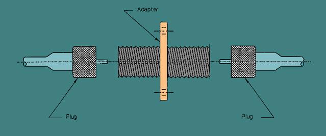
Butt-jointed connectors and expanded-beam connectors are the two basic types of fiber optic connectors. Fiber optic butt-jointed connectors align and bring the prepared ends of two fibers into close contact. The end-faces of some butt-jointed connectors touch, but others do not depending upon the connector design. Types of butt-jointed connectors include cylindrical ferrule and biconical connectors. Fiber optic expanded-beam connectors use two lenses to first expand and then refocus the light from the transmitting fiber into the receiving fiber. Single fiber butt-jointed and expanded beam connectors normally consist of two plugs and an adapter (coupling device). Figure 4-15 shows how to configure each plug and adapter when making the connection between two optical fibers.
Figure 4-15. - Plug-adapter-plug configuration.
Ferrule connectors use two cylindrical plugs (referred to as ferrules), an alignment sleeve, and sometimes axial springs to perform fiber alignment. Figure 4-16 provides an illustration of this basic ferrule connector design. Precision holes drilled or molded through the center of each ferrule allow for fiber insertion and alignment. Precise fiber alignment depends on the accuracy of the central hole of each ferrule. When the fiber ends are inserted, an adhesive (normally an epoxy resin) bonds the fiber inside the ferrule. The fiber-end faces are polished until they are flush with the end of the ferrule to achieve a low-loss fiber connection. Fiber alignment occurs when the ferrules are inserted into the alignment sleeve. The inside diameter of the alignment sleeve aligns the ferrules, which in turn align the fibers. Ferrule connectors lock the ferrules in the alignment sleeve using a threaded outer shell or some other type of coupling mechanism.
Figure 4-16. - Basic ferrule connector design.
As stated before, fiber alignment depends on an accurate hole through the center of the ferrule. Normally, ferrule connectors use ceramic or metal ferrules. The center hole is generally drilled in a metal ferrule. Drilling an accurate hole through the entire metal ferrule can be difficult. To improve fiber alignment, some metal ferrule connectors use precision watch-jeweled centering. In precision watch-jeweled centering, a watch jewel with a precision centered hole is placed in the tip of the ferrule. The central hole of the watch jewel centers the fiber with respect to the axis of the cylindrical ferrule. The watch jewel provides for better fiber alignment, because regulating the hole tolerance of the watch jewel is easier than maintaining a precise hole diameter when drilling through an entire ferrule.
The center hole in a ceramic ferrule is created by forming the ferrule around a precision wire, which is then removed. This method produces holes accurately centered in the ferrule. Most cylindrical ferrule connectors now use ceramic ferrules. The Straight Tip (ST®) connector is an example of a ceramic ferrule connector. (ST® is a registered trademark of AT&T.)
Other cylindrical ferrule connectors have a ferrule that contains both metal and ceramic. For these connectors a ceramic capillary is placed within the tip of a metal ferrule to provide for precision fiber alignment. The ceramic capillary is a ceramic tube with a small inner diameter that is just larger than the diameter of the fiber. Figure 4-17 shows the placement of the ceramic capillary within the metal ferrule.
Figure 4-17. - A ceramic capillary set within a metal ferrule.
Another type of butt-jointed connector is the biconical connector. Biconical connectors use two conical plugs, a double conical alignment sleeve, and axial springs to perform fiber alignment. Figure 4-18 is an illustration of this basic biconical connector design. Formation of the plugs and alignment sleeve involves transfer molding. Transfer molding uses silica-filled epoxy resin to mold the conical plug directly to the fiber or around a cast (precision wire). After connecting the conical plugs to the optical fibers, the fiber-end faces are polished before the plugs are inserted into the molded alignment sleeve. During fiber insertion, the inside surface of the double conical sleeve performs fiber alignment, while the axial springs push the fiber ends into close contact. If the alignment sleeve permits the fibers to actually become in contact, then the axial spring provides enough force to maintain fiber contact but prevent damage to the fiber-end faces. Normally, biconical connectors lock the fibers in alignment using a threaded outer shell.
Figure 4-18. - Biconical connector design.

Multifiber connectors join and align multifiber cables to reduce the time it takes to connect multiple fibers. One type of multifiber connector is the array connector. The array connector is used to connect individual ribbons of ribbon-type cables. The array connector is similar to the ribbon splice. In the array connector, the fibers of each ribbon are epoxied into grooves of a silicon chip so that the fiber ends protrude from the end of the chip. The chip and the protruding fibers are polished flat for connection. Each half of the connector is prepared separately before being butt-jointed. A spring clip and two grooved metal-backed plates are used to align and connect the stacked ribbons of the two ribbon cables. Array connectors may also use an alignment sleeve with V-grooved silicon chips and metal springs to align and connect stacked ribbons. Figure 4-19 shows the spring clip method of array connector alignment. The multifiber array connector is only one example of a multiple connector. Many types of multiple connectors exist that connect different types of multifiber cables.
Figure 4-19. - Spring clip method of ribbon connection.
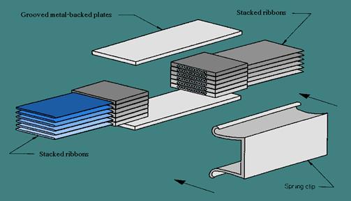
Figure 4-20 shows how an expanded-beam connector uses two lenses to expand and then refocus the light from the transmitting fiber into the receiving fiber. Expanded-beam connectors are normally plug-adapter-plug type connections. Fiber separation and lateral misalignment are less critical in expanded-beam coupling than in butt-jointing. The same amount of fiber separation and lateral misalignment in expanded beam coupling produces a lower coupling loss than in butt-jointing. However, angular misalignment is more critical. The same amount of angular misalignment in expanded-beam coupling produces a higher loss than in butt-jointing. Expanded-beam connectors are also much harder to produce. Present applications for expanded-beam connectors include multifiber connections, edge connections for printed circuit boards, and other applications.
Figure 4-20. - Expanded-beam connector operation.
EQUIPMENTS
<The following equipments are produced by Nextrom R&D >
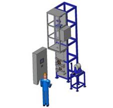
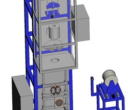
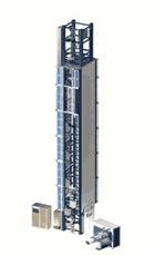
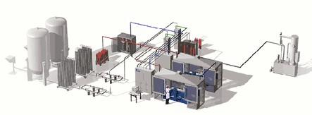
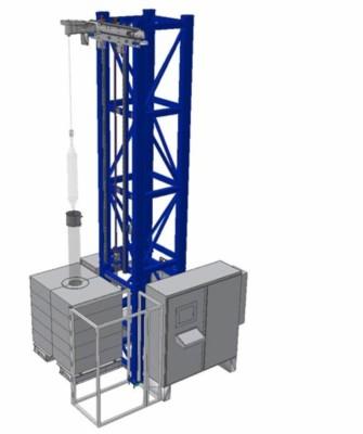
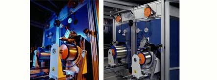
The optical drawing tower OFC 20
is designed for high quality fiber production from a wide range of preforms. The tower modules and the selection of components enable a flexible and upgradable layout. Mechanical integrity and solid construction, high quality components like the advanced drawing furnace and coating system combined with a comprehensive control system result in strong fiber and high yield. Produced fiber meets all relevant international standards and recommendations on optical, geometrical and strength properties. Our drawing tower solution also suits the most advanced research applications. Joint test runs in Nextrom's R&D facilities together with customers and suppliers provide value-added innovations.
APPLICATION
Suitable for drawing wide
range of optical preforms:
Single mode, graded index or special fiber preforms of MCVD, OVD, VAD or RIT
technologies
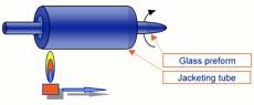
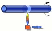
The OFC 17 for sleeving
is targeted at companies which manufacture core preforms
with MCVD and Rod-In-Tube sleeving technology. It enables these manufacturers
to increase their preform size and to lower their manufacturing costs. The OFC
17 is designed for Rod-In-Tube sleeving up to 150 mm final preform diameter.
These companies can also scale their big preform diameters to fit their
existing fiber draw furnaces.
The OFC 17 is also targeted for companies, which use soot technology for
manufacturing their preforms. These companies can stretch their core preforms,
split them into several pieces for further processing and then again stretch
the final preform to scale it to fit their existing fiber draw furnaces.
APPLICATION
Rod in tube sleeving
Stretching
Tube stretching
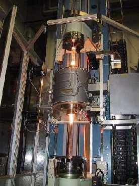
Sleeving Lathe OFC 16
The horizontal sleeving lathe is designed to fulfil requirements of a large diameter preform processing. The lathe is suitable for rod-in-tube sleeving process as well as for large diameter preform fire polishing and glass working. It is supplied with all the necessary instrumentation needed for high quality sleeving work and is equipped with special metal burner optimized for large preforms. OFC16 sleeving lathe has a modern rigid structure that guarantees reliable operation over the years.
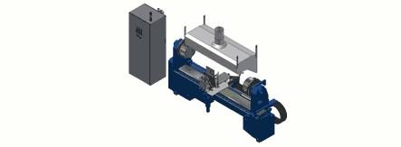
APPLICATION
ROD IN TUBE SLEEVING
Purpose:
![]()
The horizontal glass-working lathe is designed to fulfil requirements of a large diameter preform processing. The lathe is suitable for various glass-working operations as well as for large diameter preform fire polishing. It is supplied with all the necessary instrumentation needed for high quality glass working and is equipped with special metal burner optimized for large preforms. The flame form can be easily adjusted for different glass working operations. OFC15 glass working lathe has a modern rigid structure that guarantees reliable operation over the years.
APPLICATION
Fire polishing:
Glass working:
![]()
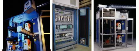
Modified Chemical Vapor Deposition is a widely used method for the fabrication of high quality optical fiber preforms. Nextrom MCVD system OFC 12 is designed to fulfil the requirements of the fast moving fiber optics and photonics industries. The latest technology applied in OFC 12 results in low start-up investment, quick set-up and easy to customize solutions. Advanced process monitoring and control optimizes the yield of preform fabrication and allows a wide product range. The modular construction can also be adapted to meet requirements of various silica fiber types. Process stability, repeatability and good contamination control combined with quick set-up, as well as easy maintenance and space reduction are the main advantages of OFC 12.
APPLICATION
Single mode preforms
Multi mode preforms
Special preforms
![]()
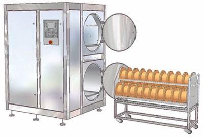
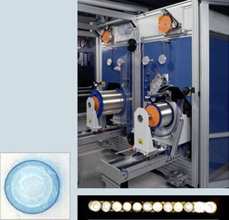
Nextrom deuterium treatment system NDS is designed to be used for treating Low Water Peak Fibers (ITU-G.652C) with deuterium gas. The deuterium treatment ensures, that OH-related attenuation does not rise during the life time of the optical fiber. NDS is a modular system, which can easily be tailored for different treatment capacities. It comes in 12 different standard configurations all having different treatment capacity. The smallest system has an approximate treatment capacity of 50 thousand fiber kilometers per year and the largest standard system has an approximate annual treatment capacity of 2 million fiber kilometers. NDS has a high degree of automation and has been designed from a mass production point of view. NDS has both low investment cost and low cost of operation per treated fiber kilometer. NDS is offered for standard 25 kilometer fiber reels, but it is also available for standard 50 kilometer fiber reels and can be customized for bigger reels as well.
![]()
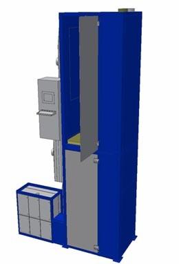
Nextrom soot preform sintering system OFC 08 can be used for sintering soot core preforms or soot overcladded preforms. The structure of OFC 08 is modular and the system can be tailored for different preform sizes up to 2 meters in length, 250 mm in diameter (before sintering) and up to 60 kgs in weight. OFC 08 converts the soot layers deposited with OFC 06 soot deposition system to solid vitrified, high-strength and high-quality glass. Two different versions of OFC 08 are available, one is for sintering soot overcladded preforms and the other one is for sintering VAD core preforms. The version, which is designed for LWPF (low water peak fiber) core preform sintering includes special process steps to ensure a very low water peak in the finished fiber, compliant with ITU-G.652C specification. The benefits of using soot preform sintering system OFC 08 together with soot deposition system OFC 06 are low material and production costs as well as high fiber strength and quality.
![]()
Nextrom
soot deposition system OFC 06 can be used for soot overcladding of core
preforms, which are made with any commercial preform manufacturing method
(MCVD, PCVD, OVD or VAD). Another version of OFC 06 can be used for fabricating
VAD core preforms for producing for example Low Water Peak Fiber (according to
ITU-G.652C specification).
Nextrom's OFC 06 for soot overcladding is a vertical soot deposition system
being capable of soot overcladding up to 2 meter long preforms and having twice
as high productivity as any other commercially available soot overcladding
equipment. Compared to tube sleeving, the advantages of soot overcladding are
lower material and production costs, enhanced fiber geometry with improved
cut-off wavelength control and proof test as well as fiber final test yields.
Vertical OFC 06 for soot overcladding can be used to overclad
preforms up to a size, which is equivalent to 1800 km of fiber drawn from each
preform.
Nextrom's OFC 06 for VAD core preform manufacturing is also a vertical soot
deposition system, which is capable of making up to 2 meter long core preforms.
OFC 06 system for VAD core preforms is a very good tool for making Low Water
Peak Fiber preforms. Other benefits are good core preform geometry and low material
and production costs. Each core preform can yield up to 2000 kilometers of
optical fiber.
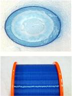
![]()
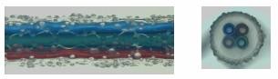
The optical fiber ribbon system OFC 21 produces all types of optical fiber ribbons at high production speeds. OFC 21 offers the best performance. High quality ribbons manufactured with this advanced line have excellent optical and mechanical properties and accurate dimensions. Produced optical fiber ribbons fulfill all major standards. The coloring of the fibers can be tandemized in the process thus improving the production efficiency by minimizing the set-up times. We have a long experience with ribbon machinery and many deliveries worldwide guarantee real industrial design. Joint test runs in Nextrom's R&D facilities together with customers and suppliers provide value-added innovations.
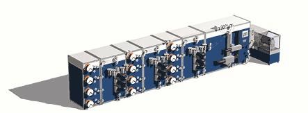
APPLICATION
Ribbon up to 24 Fiber (2-24F)
Encapsulated or Edge bonded
![]()
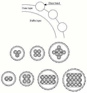
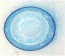
Nextrom
new Blown Fiber (EPFU) System OFC 22 is based on long experience with ribbon
lines, UV-curing and fiber handling technology. OFC 22 is designed for high
line-speeds, high capacity and minimum scrap and down-time to reduce the
manufacturing cost. The line features include two vertical coating stages,
called primary and secondary coating, with independent, automated acrylate
feeding systems. The secondary coating unit includes a glass bead-spraying unit
for surface treatment. The line will physically fit into average clean rooms
since no tower structure is required. By changing coaters, materials and guide
pulleys, the line can also be used to produce other products like; standard
ribbons, split-ribbons, UV tight-buffered fibers and colored fibers.
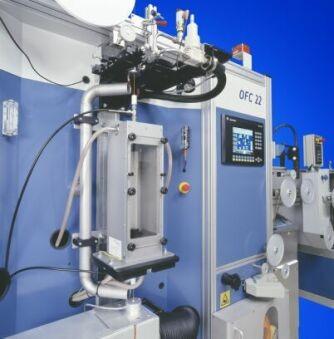
APPLICATION
Surface roughness and low friction achieved by spraying glass beads onto outer acrylate layer
Based on UV-acrylate technolgy
2 - 12 fiber products
Both fiber bundle and ribbon are possible
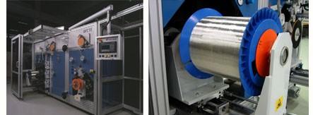
![]()
Recent research and studies on fiber strength served as a basis for designing the proof testing and rewinding system OFC 35. Special solutions guarantee the winding quality within the whole speed range. We offer better production efficiency - increased speed and maximum uptime combined with accurate proof testing tension. Our compact design requires only a small foot print. Over 180 delivered OFC 35 systems guarantee proven technology.
APPLICATION
OFC 35 can be tailored for
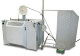
![]()
OFC 52 is Nextrom's basic coloring system. It is proven technology with over 200 deliveries worldwide. A smooth and concentric color layer and a high intensity UV curing system guarantee good optical characteristics and optimum curing rate of the colored fiber. Perfect winding at all speeds up to 1800m/min is guaranteed by efficient servo motors, sensitive dancers and automatic turning point control. We offer competitive production efficiency - high quality with short set up time. Easy to use compact design requires only a small foot print.
APPLICATION
For Single Mode Fiber, Multi Mode Fiber or Special
Coloring typically to diameter 250 µm - 260 µm
UV acrylate upcoating to 400 µm - 900 µm
Ring Marking with single or double marks, 25 mm or 50 mm intervalls
![]()
OFC 55 is a tandemized coloring and proof testing system. OFC 55 is based on Nextrom's basic coloring and proof testing systems. This unit can be used also separately either for coloring or proof testing. Special attention is paid to high quality processing, take-up and pay-off, short set up times, easy operation and maintenance. Perfect winding with high speed is guaranteed by efficient servo motors, sensitive dancers and automatic turning point control. Safety doors cover both the reels and the whole line during the run.
APPLICATION
Proof Testing and Rewinding
Coloring
EQUIPMENT PRESENTATION
Plastic Optical
Automation Engineering's POF drawing tower is ideal for both research and volume production applications involving plastic optical fiber (POF).
RIGID CONSTRUCTION:
|
|
PRECISION COMPONENTS:
PC-BASED FLEXAUTO CONTROL SYSTEM:
TECHNICAL CHARACTERISTICS:
|
Drawing Speed |
up to 20 feet/second |
|
Tower Height |
up to 18 feet |
|
Max. Boule Length |
50 inches |
|
Take-up Spool Capacity |
500 miles |
|
Max. No. of Spools |
2 |
|
Fiber Diameter Accuracy |
± 0.000025 inches |
|
Boule Feed Speed Accuracy |
± 0.01% |
|
Max. Drawing Temperature |
600° F |
Quartz Optical
The AEi quartz fiber drawing tower is capable of drawing PCS, HCS, and silica/silica fiber. The design features manufacturing reliability with the flexibility for both research and volume production applications.
RIGID CONSTRUCTION:
PRECISION COMPNENTS
PC-BASED FlexAutoT CONTROL SYSTEM
TECHNICAL CHARACTERISTICS:
|
Drawing Speed |
up to 80 feet/second |
|
Tower Height |
up to 30 feet |
|
Max. Preform Length |
50 inches |
|
Max. No. of Preforms |
1 |
|
Take-up Spool Capacity |
500 miles |
|
Max. No. of Spools |
2 |
|
Fiber Diameter Accuracy |
± 0.000025 inches |
|
Preform Feed Speed Accuracy |
± 0.01% |
|
Max. Drawing Temperature |
2400° C |
The following equipments are manufactured
by
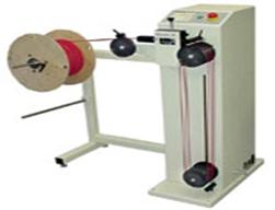
The PreFeeder 4600 is the ideal feeding system for high performance cable processing lines with spools weighing up to 600 kg (1'334 lbs.). The system is characterized by a rugged construction and powerful drive.
For easy spool handling, all required axis are motorized. They can be easily controlled by a simple remote control. Thanks to the special spool clamping concept, no heavy spool shafts or clamps have to be used.
The PreFeeder 4600 is a powerful and highly reliable cable feeding system improving the flexibility and quality of your entire production line. Fast spool changeovers are guaranteed by simple handling and motorized axis. For easy handling of heavy spools, an optional air cushion device is also available - allowing one operator to handle even the heaviest spools single-handedly.
Various cable accumulating systems are available to achieve highly dynamic dereeling processes tailored to your application. An automatic interrupt-circuit guarantees safety when reaching the cable end or in case of a faulty coil on the spool.
|
Machine |
PreFeeder 4600 |
||||||
|
Reel Diameter (O.D.) |
1'050 mm (41.3") |
||||||
|
Reel Arbor Diameter |
38 - 125 mm (1.5" - 4.9") |
||||||
|
Max. Reel Width |
750 mm (29.5") |
||||||
|
Max. Reel Weight |
600 kg (1'334 lbs.) |
||||||
|
Max. Cable Diameter |
35 mm (1.38") in combination with a
pendulum arm system |
||||||
|
Max. Dereeling Speed |
143 rpm |
||||||
|
Cable Accumulator Volume |
Depending on the control / storage system and system lay out |
||||||
|
System Dimensions |
|
||||||
|
Power Supply |
3 x 400 VAC + N / 32 AT |
||||||
|
Air Pressure |
6 bar (87 psi) |
||||||
|
CE-Compatibility |
The PreFeeder 4600 fully complies with all CE and EMC equipment guidelines relative to mechanical and electrical safety and electromagnetic compatibility. |
The PreFeeder 2200 is a free-standing, electrical prefeeding machine designed to pull wire and cable from reels weighing up to 50 kg (110 lbs.).
A proven accumulator allows the PreFeeder 2200 to easily respond to the typical intermittent starting and stopping actions associated with automatic wire processing machines.
The PreFeeder 2200 is equipped with a powerful motor drive for feeding speeds up to 2.5 m/s (8.2 ft/s). The large accumulator capacity of 3.8 m (12.5 ft.) easily handles high speed / high acceleration processing.
The wide belts of the PreFeeder 2200 pull cables up to 15 mm (0.6") in diameter.
Its powerful front-loading operating head makes it easy to load and unload cables for production changeovers. The PreFeeder 2200 has a specially designed ergonomic panel height with simple controls for easy access and operation.
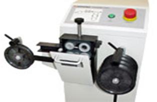
A universally adjustable cable guide eliminates individual guides - no need to change guides for different applications. Save time and forget about guides that have been misplaced.
|
Machine |
PreFeeder 2200 |
|
Max. Cable Diameter (O.D.) |
15 mm (0.6") |
|
Max. Cable Reel Diameter |
762 mm (30'') |
|
Max. Cable Reel Width |
457 mm (18") |
|
Max. Cable Reel Weight |
50 kg (110 lbs.) |
|
Shaft Length |
510 mm (20") |
|
|
19 - 65 mm (0.75" - 2.5") |
|
Feed Rate |
up to 2.5 m/s (8.2 ft/s) |
|
Max. Pulling Force |
680 N from cable rack |
|
Dimensions |
978 x
762 x 1143 mm |
|
Power Supply |
100 /
115 VAC |
|
Weight |
65 kg (143 lbs.) |
|
CE-Compatibility |
The PreFeeder 2200 fully complies with all CE and EMC equipment guidelines relative to mechanical and electrical safety and electromagnetic compatibility. |
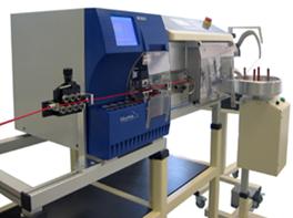
Wire labeling is a common application where wire identification is needed and where ink jet or hot stamp marking cannot be used. It is typically a very labor-intensive job but now, for the first time, this process can be completely automated to improve accuracy and efficiency and to reduce cost.
Schleuniger Inc.has teamed with Brady Corporation to create an in-line labeling system comprised of the new Brady Wraptor Wire ID Printer Applicator and Schleuniger's latest cut and strip machines.
Perfect for hard-to-mark applications that can not be marked with inkjet or hot stamp - this includes Teflon and any other applications that do not allow hot stamp marking
Marking versatility - print logos, bar codes, time, date, and even sequencing serial numbers for each wire in alphanumeric, hex, octal and other formats
Label placement flexibility - eliminate label placement limitations and minimum wire length limitations when using the Wraptor as a stand-alone unit
More efficient than using the Wraptor as a stand-alone unit - labels are automatically located and wrapped thereby eliminating placement and reducing labor costs. Per-piece costs can be reduced by up to 60%.
Programmability - easily recall all wire and labeling information in a few easy steps
Integrated pre-& post-processing wire management
PreFeeder 2200 Prefeeding Machine
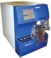
Brady Wraptor Wire ID Printer Applicator with Schleuniger In-Line Interface
Equipment Rack with Wire Guide and Straightener
PowerStrip 9500 Automatic Wire Cutting and Stripping Machine (as shown)
Any Schleuniger Automatic Cable Coiling Machine or Stacking Machine
|
System |
Wire and Cable Labeling System |
|
Wire/Cable O.D. |
0.060" - 0.600" (1.52 mm - 15 mm) |
|
Wrapping Cycle Time |
4.5 - 6.5 seconds per label |
|
Labeling Types |
End, continuous, others |
|
Minimum Wire Length |
One label width |
|
Min. Distance to End of Wire |
One strip width |
|
Compatible Machines |
EcoStrip 9300, OmniStrip 9400, PowerStrip 9500, MegaStrip 9600 (limited to cable < 15 mm O.D.), OC 3950 |
|
CE-Compatibility |
This system fully complies with all CE and EMC equipment guidelines relative to mechanical and electrical safety and electromagnetic compatibility. |
The low-cost FiberOptic 7010 cuts and removes the Kevlar material of fiber optic cables with complete accuracy to a remaining length between 3 and 60 mm (0.12 and 2.36").
An efficient vacuum system, activated by means of a foot pedal, separates the Kevlar material from the optical conductor of the cable. The Kevlar is then positioned between the cutting head and anvil. The number of cutting strokes can be adapted to the thickness of the material by means of operating the foot pedal several times.
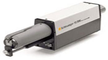
This extremely light benchtop machine is easy to operate and guarantees repeatable results and a precise cutting performance.
The FiberOptic 7010 is best deployed in a work cell with other Schleuniger machines for Glass Optical Fiber (GOF) processing:
OmniCut 3950: cutting to length
UniStrip 2545: the jacket is stripped partially and can easily be removed by hand
FiberOptic 7010: severing and removal of the Kevlar strands
FiberStrip 7030 or FiberStrip 7035: stripping of the buffer and / or coating
Alternatively, all of the operations except for cutting to length can also be performed automatically with the FiberOptic 7045.
|
|
Glass Optical Fiber GOF |
|
|
Duplex Glass Optical Fiber |
|
|
Simplex cable with secondary strength member and outer jacket |
|
|
Fiber ribbon |
|
Machine |
FiberOptic 7010 |
|
Wire / Cable |
All cables containing Kevlar strength member |
|
Means of Cutting |
anvil and cutter |
|
Max. Cable O.D. |
4.5 mm (0.18") |
|
Shortest Length of Remaining Kevlar |
3 mm (0.12") |
|
Max. Length of Remaining Kevlar |
60 mm (2.36") |
|
Max. Length of Kevlar to be Cut |
30 mm (1.18") |
|
Cycle Time |
> 3 sec. (depending on number of strokes) |
|
Interfaces |
Foot pedal (included) |
|
Power Supply |
100/115/230 VAC, 50 / 60 Hz |
|
Compressed Air Requirement |
0.5 - 0.7 MPa (75 - 105 psi) |
|
Dimensions (L x W x H) |
Cutting machine: 600 x 75 x 130 mm (23.6
x 3 x 5.1") |
|
Weight |
Cutting machine: 3 kg (6.6. lbs.) |
|
CE-Conformity |
The FiberOptic 7010 fully complies with all CE and EMC equipment guidelines relative to mechanical and electrical safety and electromagnetic compatibility. |
The WireStacker 1000 is a passive wire stacking system with guide channel and collecting tray. It handles cable lengths up to 3 m (10 ft) and wires as small as 0.34 mm2 (AWG 22).
After processing of each wire, the cut & strip machine sends a signal to the stacker initiating the dropping of the wire from the guide channel into the collecting tray. All programming such as total and batch quantities is done on the cut & strip machine.
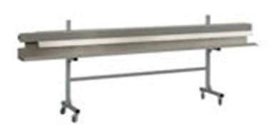
The WireStacker 1000 is the ideal low-cost solution for the post-processing of both, short and long cables. It allows unattended operation. This wire stacker is optimized for use with Schleuniger cutting and cut & strip machines, thus permitting trouble-free and efficient processing.
Take the product tour for technical specifications.
In order to maintain the quality of a carefully processed cable, it is highly recommended to use post-processing equipment such as a wire stacking or a cable coiling machine.
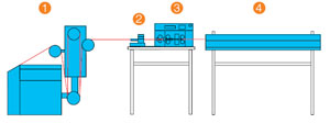
Processing line with prefeeder (1), marker (2), processing machine (3) and wire stacker (4).
|
Machine |
WireStacker 1000 |
||||
|
Cable Size |
|
||||
|
|
Up to 3000 mm (118.1") |
||||
|
Height of Wire Axis |
Adjustable from 610 mm (24") up to 1'060 mm (41.7") |
||||
|
Control Signal Requirements |
24 VDC timed control signal |
||||
|
Air Pressure |
70 - 90 psi |
||||
|
Air Consumption |
< 0.03 m² / min. at 550 kPa (< 1 CFM at 80 psi) |
||||
|
Dimensions |
3000 x 470 x 1'170 mm |
||||
|
Weight |
55 kg (122 lbs.) |
||||
|
CE-Compatibility |
The WireStacker 1000 fully complies with all CE and EMC equipment guidelines relative to mechanical and electrical safety and electromagnetic compatibility. |
The CableCoiler 4000 is a motorized heavy-duty cable coiling machine designed to interface with the MegaStrip 9600. It coils cable up to an inner diameter of 600 mm (23.6") and handles cable coils weighing up to 80 kg (178 lbs.)
Thanks to its flexibility, easy programming and ergonomic handling, the CableCoiler 4000 is a perfect solution to improve the production rate as well as the efficiency in a production line.
The CableCoiler 4000 operates with the MegaStrip 9600 in a fully synchronized mode. The cable is fed from the MegaStrip 9600 through a guide directly to the coiler pins. The CableCoiler 4000 coils the cable simultaneously to the feeding speed of the MegaStrip 9600. After the coiling process, the coiler pins retract and the safety cover opens. The coiled cable can easily be removed from the machine.
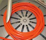
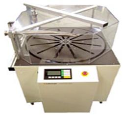
Coiled cable on the turntable with retracted pins
for easy removing of the coiled material
|
Machine |
CableCoiler 4000 |
|
Cable Diameter |
Up to 35 mm (1.38") depending on the flexibility of the cable |
|
Coil Inner Diameter |
250 - 600 mm (9.8" - 23.6") |
|
Max. Coil Outer Diameter |
750 mm (29.5") |
|
Max. Coil Weight |
80 kg (177.8 lbs.) |
|
Max. Coiling Speed |
2 m / s (6.56 ft) |
|
Interface |
MSINC on MegaStrip 9600 |
|
Power Supply |
230 VAC, 50 Hz |
|
Compressed Air |
6 bar (90 psi) operating pressure |
|
Weight |
180 kg (400 lbs.) |
|
Dimensions (H x W x D) |
1'230 x 1'060 x 1'260 mm |
|
CE-Compatibility |
The CableCoiler 4000 fully complies with all CE and EMC equipment guidelines relative to mechanical and electrical safety and electromagnetic compatibility. |
|