This publication, including all photographs, illustrations and software, is protected under international copyright laws, with all rights reserved. Neither this manual, nor any of the material contained herein, may be reproduced without the express written consent of the manufacturer.
The information in this document is subject to change without notice. The manufacturer makes no representations or warranties with respect to the contents hereof and specifically disclaims any implied warranties of merchantability or fitness for any particular purpose. Further, the manufacturer reserves the right to revise this publication and to make changes from time to time in the content hereof without obligation of the manufacturer to notify any person of such revision or changes.
IBM, VGA, and PS/2 are registered trademarks of International Business Machines.
AMD and Athlon are registered trademarks of Advanced Micro Devices Inc.
Intel, Pentium, Pentium-II, and MMX are registered trademarks of Intel Corporation.
Microsoft, MS-DOS and Windows 95/98/NT are registered trademarks of Microsoft Corporation.
Sound Blaster is a trademark of Creative Technology Ltd.
PC-cillin and ChipAwayVirus are trademarks of Trend Micro Inc.
Award is a trademark of Award Software Inc.
A3D is a registered trademark of Aureal Inc.
MediaRing Talk is a registered trademark of MediaRing Inc.
Other names used in this publication may be trademarks and are acknowledged.
Copyright © 2000
All Rights Reserved
M805LR, V1.0
V83X/June 2000
Information:
This mainboard may support 266MHz FSB for specification, but AMD can NOT provide this kind of K7 CPU to verify it.
Table of Contents
Chapter 1: Introduction
Key Features
Package Contents
Static Electricity Precautions
Pre-Installation Inspection
Chapter 2: Mainboard Installation
Mainboard Components
I/O Ports
Install A CPU
Install Memory
Setting Jumper Switches
Install the Mainboard
Install the Extension Brackets
Optional Extension Brackets
Install Other Devices
Expansion Slots
Chapter 3: BIOS Setup Utility
Introduction
Running the Setup Utility
Standard CMOS Features Page
Advanced BIOS Features Page
Advanced Chipset Features Page
Integrated Peripherals Page
Power Management Setup Page
PnP/PCI Configurations Page
Hardware Monitor Page
CPU Plug and Play Page
Load Best Performance Defaults
Load Optimized Defaults
Set Password
Save & Exit Setup
Exit Without Saving
Chapter 4: Software & Applications
Introduction
Installing Support Software
Auto-installing under Windows 98
Appendix A: Corel WordPerfect
Welcome to Corel WordPerfect Suite 8 A2
Installing Corel WordPerfect
Learning how to use Corel WordPerfect Suite 8 A9
Support and Services A13
This mainboard has a Socket-462
processor socket for an AMD K7 type
CPUs. You can install any one of these processors on the mainboard.
The mainboard supports Socket-462 processor front-side bus speeds of 200MHz or 266MHz.
This mainboard uses the VIA VT8363 chipset which provides a 4X AGP slot for highly graphics display, CPU Plug & Play through firmware. The mainboard has a built-in AC97 Codec, provides an AMR (Audio Modem Riser) slot to support Audio and Modem application, and has a built-in 10BaseT/100BaseTX Network Interface. In addition, the mainboard has an extended set of ATX I/O Ports including PS/2 keyboard and mouse ports, two USB ports, an RJ-45 LAN port, a parallel port, and two serial ports. Two 19119k102t extra USB ports can be added using the Extended USB Module that connects to the mainboard.
This mainboard has all the features you need to develop a powerful multimedia workstation that is network ready. The board is Micro ATX size and has power connectors for an ATX power supply.
The key features of this mainboard include:
Supports AMD Athlon/Duron processors
Supports 200/266 MHz Front-Side Bus
Processors are automatically configured using firmware and a synchronous Host/DRAM Clock Scheme.
Two DIMM slots for 168-pin SDRAM memory modules
Support for 100/133 MHz memory bus
Maximum installed memory is 2 x 512MB = 1GB
One AMR slot for a special audio/modem riser card
One AGP4X slot for AGP 2.0-compliant interface.
Two 32-bit PCI slots for PCI 2.2-compliant bus interface.
Primary and Secondary PCI IDE channels
Support for PIO (programmable input/output) modes
Support for Multiword DMA modes
Support for Bus Mastering and Ultra DMA 33/66 modes
ATX power supply connector
ACPI and previous PMU support, suspend switch, keyboard power on/off
Supports Wake on Modem, Wake on LAN and Wake on Alarm
Compliant PC97 2.1 specification
Supports 18-bit ADC (Analog Digital Converter) and DAC (Digital Analog Converter) as well as 18-bit stereo full-duplex codec
Provides PC99 Color Connectors for easy peripheral device connections
Floppy disk drive connector with 1Mb/s transfer rate
Two serial ports with 16550-compatible fast UART
One parallel port with ECP and EPP support
Two USB ports, optional two USB ports module
Two PS/2 ports for keyboard and mouse
One infrared port connector for optional module
Built-in hardware monitoring for CPU & System temperatures, fan speeds and mainboard voltages
Built-in 10BaseT/100BaseTX Ethernet LAN
LAN controller integrates Fast Ethernet MAC and PHY compliant with IEEE802.3u 100BASE-TX, 10BASE-T and ANSI X3.263 TP-PMD standards
Compliant with ACPI 1.0 and the Network Device Class Power Management 1.0
High Performance provided by 100Mbps clock generator and data recovery circuit for 100Mbps receiver
Automatic CPU and board configuration
Supports Plug and Play configuration of peripheral devices and expansion cards
Built-in virus protection using Trend's ChipAwayVirus provides boot process virus protection.
PC-Cillin provides automatic virus protection under Windows 95/98
MediaRing Talk provides PC to PC or PC to Phone internet phone communication
S-YXG50
is music synthesizer software to playback
Corel
WordPerfect
Micro ATX form factor (24.4cm x 22cm)
Your mainboard package ships with the following items:
q The mainboard
q This User's Guide
q 1 UDMA/66 IDE cable
q 1 Floppy disk drive cable
q Support software on CD-ROM disk
You can purchase the following optional accessories for this mainboard.
q Extended USB module
Components on this mainboard can be damaged by static electricity. Take the following precautions when unpacking the mainboard and installing it in a system.
Keep the mainboard and other components in their original static-proof packaging until you are ready to install them.
During installation, wear a grounded wrist strap if possible. If you don't have a wrist strap, discharge static electricity by touching the bare metal of the system chassis.
Handle the mainboard carefully by the edges. Avoid touching the components unless it is absolutely necessary. During installation put the mainboard on top of the static-protection packaging it came in with the component side facing up.
Inspect the mainboard for damage to the components and connectors on the board.
If you suspect that the mainboard has been damaged, do not connect power to the system. Contact your mainboard vendor and report the damage.
To install this mainboard in a system, follow the procedures in this chapter:
q Identify the mainboard components
q Install a CPU
q Install one or more system memory modules
q Verify that any jumpers or switches are set correctly
q Install the mainboard in a system chassis (case)
q Connect any extension brackets or cables to the mainboard connector headers
q Install any other devices and make the appropriate connections to the mainboard connector headers.
Note:
Before
installing this mainboard, make sure jumper JP1 is set to
Never connect power to the system during installation. Doing so may damage the mainboard.
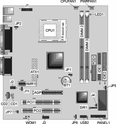
Use the diagram below to identify the major components on the mainboard.
Note: Any jumpers on your mainboard that do not appear in this illustration are for testing only.
The illustration below shows a side view of the built-in I/O ports on the mainboard.
This mainboard has a Socket-462 CPU socket for AMD K7 processors.
To ensure reliability, ensure that your processor has a heatsink/cooling fan assembly.
Do not try to install a Socket-370/Socket-7 processor in the Socket-462. A Socket-370/Socket-7 processor such as the PPGA Celeron, FCPGA Pentium-III, Pentium-MMX, or the AMD K5/K6 does not fit in the Socket-462.
The following list notes the processors that are currently supported by this mainboard.
Athlon: 650 MHz~Unlimited, FSB: 200 MHz
Duron: 550~850 MHz, FSB: 200 MHz
A processor installs into the ZIF (Zero Insertion Force) Socket-462 on the mainboard.
Locate the Socket-462 and CPUFAN1. Pull the locking lever out slightly from the socket and raise it to the upright position.
![]()

![]()


![]()
On the processor, identify the Pin-1 corner by its beveled edge.
On the Socket-462, identify the Pin-1 corner. The Pin-1 corner is at the top of the locking lever when it is locked.
Match the Pin-1 corners and insert the processor into the socket. No force is required and the processor should drop into place freely.
Swing the locking lever down and hook it under the catch on the side of the socket. This secures the CPU in the socket.
All processors should be installed with a combination heatsink/cooling fan (the original fan is recommended, the others' fan is not), connect the cable from the fan to the CPU fan power connector CPUFAN1.
The mainboard has two DIMM sockets for system memory modules. You must install at least one memory module in order to use the mainboard.

![]()
For this mainboard, you must use 168-pin, 3.3V unbuffered PC100 or PC133 SDRAM memory modules. You can install any size memory module from 32 MB to 512MB, so the maximum memory size is 2 x 512MB = 1GB.
The edge connectors on the memory modules have cut outs, which coincide with spacers in the DIMM sockets so that memory modules can only be installed in the correct orientation.
To install a module, push the retaining latches at either end of the socket outwards. Position the memory module correctly and insert it into the DIMM socket. Press the module down into the socket so that the retaining latches rotate up and secure the module in place by fitting into notches on the edge of the module.
Jumpers are sets of pins which can be connected together with jumper caps. The jumper caps change the way the mainboard operates by changing the electronic circuits on the mainboard. If a jumper cap connects two pins, we say the pins are SHORT. If a jumper cap is removed from two pins, the pins are OPEN.
![]()

![]()
Use this jumper to clear the contents of the CMOS memory. You may need to clear the CMOS memory if the settings in the Setup Utility are incorrect and prevent your mainboard from operating. To clear the CMOS memory, disconnect all the power cables from the mainboard and then move the jumper cap into the CLEAR setting for a few seconds.
|
Function |
Jumper Setting |
|
Normal Operation |
Short Pins 1-2 |
|
Clear CMOS Memory |
Short Pins 2-3 |
Use this jumper to enable device activity on USB ports 1-2 to power on the computer.
|
Function |
Jumper Setting |
|
Disable |
Short Pins 1-2 |
|
Enable |
Short Pins 2-3 |
Use this jumper to select the onboard audio codec or Audio Modem Riser (AMR) slot.
|
Function |
Jumper Setting |
|
Use onboard codec |
Short Pins 1-2 |
|
Use AMR slot codec |
Short Pins 2-3 |
Use this jumper to make the BIOS read-only.
|
Function |
Jumper Setting |
|
Disable |
Short Pins 1-2 |
|
Enable |
Short Pins 2-3 |
Use this jumper to enable device activity on USB ports 3-4 to power on the computer.
|
Function |
Jumper Setting |
|
Disable |
Short Pins 1-2 |
|
Enable |
Short Pins 2-3 |
Use this jumper to define the onboard codec mode function.
|
Function |
Jumper Setting |
|
Master |
Open Pins 1-2 |
|
Slave |
Short Pins 1-2 |
Install the mainboard in a system chassis (case). The board is an Micro ATX size mainboard with a twin-tier of I/O ports. You can install this mainboard in any ATX case. Ensure that your case has an I/O cover plate that matches the ports on this mainboard.
Install the mainboard in a case. Follow the instructions provided by the case manufacturer using the hardware and internal mounting points on the chassis.
J1
![]()
![]()
![]()
![]()

Connect the power connector from the power supply to the ATX1 connector on the mainboard.
If there is a cooling fan installed in the system chassis, connect the cable from the cooling fan to the PWRFAN1 fan power connector on the mainboard.
This motherboard provides J1 header for an auxiliary front-oriented infrared/keyboard/mouse connector. Depending on your case and system configuration this header may be more suitable as these ports connector.
This motherboard provides J2 header for an auxiliary front-oriented Microphone/Audio Line-Out connector which easier access.
The J4 header is
for plug-in-the Dual Color LED (for example, red and green) which can be bought
by the customers themselves. It can be indicate several conditions as shown the
following tables. S1(POS) - Software
power down. S3(STR) - Suspend to RAM. S4 - Suspend to Disk. S5 - Soft off. The
header is not defined, but we suggest that "red" stands for Color 1 (S1/S3),
"green" stands for Color 2 (
|
5VSB |
Dark |
|
Power On |
Color 2 light on |
|
S1/S3 mode |
Color 1 Blinking |
|
S4/S5 mode |
Dark |
Connect the case switches and indicator LEDs to the PANEL1 switch and LED connector header. See the illustration below for a guide to the header pin assignments.

The extension brackets are used to connect features on the mainboard to external connectors that can be attached to the system chassis. Follow the steps below to install the extension brackets.
Note: All the ribbon cables used on the extension brackets have a red stripe on the Pin-1 side of the cable.
This bracket supports an RJ45 network connector and connects to the built in J3 LAN header on the mainboard.


On the mainboard, locate the J3 LAN header for this bracket.
Plug the cable from the bracket into the LAN header.
In the system chassis, remove a blanking plate from one of the expansion slots and install the extension bracket in the slot. Use the screw that held the blanking plate in place to secure the extension bracket.
For this mainboard, you can also obtain a USB module extension bracket. Install them by following the steps below.
This module bracket has two USB ports for more USB devices (USB port 3-4).
USB2 Header Header

![]()
Locate the USB2 header on the mainboard.
Plug the bracket cable onto the USB2 header.
In the system chassis, remove a slot cover from one of the expansion slots and install the extension bracket in the opening. Use the screw that held the slot cover in place to secure the extension bracket to the chassis.
Install and connect any other devices in the system following the steps below.

IDE2 IDE1 FDD1
![]()
1 1
The mainboard ships with a floppy disk drive cable that can support one or two drives. Drives can be 3.5" or 5.25" wide, with capacities of 360K, 720K, 1.2MB, 1.44MB, or 2.88MB.
Install your drives and connect power from the system power supply. Use the cable provided to connect the drives to the floppy disk drive header FDD1.
IDE devices include hard disk drives, high-density diskette drives, and CD-ROM or DVD-ROM drives, among others.
The mainboard ships with an IDE cable that can support one or two IDE devices. If you connect two devices to a single cable, you must configure one of the drives as Master and one of the drives as Slave. The documentation of the IDE device will tell you how to configure the device as a Master or Slave device. The Master device connects to the end of the cable.
Install the device(s) and connect power from the system power supply. Use the cable provided to connect the device(s) to the Primary IDE channel connector IDE1 on the mainboard.
If you want to install more IDE devices, you can purchase a second IDE cable and connect one or two devices to the Secondary IDE channel connector IDE2 on the mainboard. If you have two devices on the cable, one must be Master and one must be Slave.
If you have installed a CD-ROM drive or DVD-ROM drive, you can connect the drive audio cable to the onboard sound system.
On the mainboard, locate the two 4-pin connectors CD1 and CD2. There are two kinds of connector because different brands of CD-ROM drive have different kinds of audio cable connectors. Connect the cable to the appropriate connector.
![]()


You can connect an infrared port to the mainboard. You can purchase this option from third-party vendors.
Locate the infrared port SIR1 header on the mainboard.
If you are adding an infrared port, connect the ribbon cable from the port to the SIR1 header and then secure the port to an appropriate place in your system chassis.
This mainboard has two 32-bit PCI expansion slots, one AMR slot and one AGP slot.
|
PCI2 |
|
PCI1 |
|
AGP |
|
AMR1 |
|
WOM1 Header |
Follow the steps below to install a PCI/AMR/AGP expansion card.
Locate the AGP, AMR or PCI slots on the mainboard.
Remove the slot cover for this slot from the system chassis.
Insert the expansion card edge connector into the slot and press it firmly down into it so that it is fully inserted.
Secure the expansion card bracket to the system chassis using the screw that held the slot cover in place.
The AMR (Audio Modem Riser) slot is an industry standard slot that allows for the installation of a special audio/modem riser card. Different territories have different regulations regarding the specifications of a modem card. You can purchase an AMR card that is approved in your area and install it directly into the AMR slot.
If you have installed a fax/modem card, connect the fax/modem to the Wake On Modem connector WOM1. You can then use the setup utility to program your computer to resume from a power saving mode whenever there is an incoming call to the fax/modem.
The BIOS Setup Utility records settings and information about your computer such as the date and time, the kind of hardware installed, and various configuration settings. Your computer uses this information to initialize all the components when booting up and functions as the basis for coordination between system components.
If the Setup Utility configuration is incorrect, it may cause the system to malfunction. It can even stop your computer from booting properly. If this happens, you can use the clear CMOS jumper to clear the CMOS memory used to store the configuration information, or you can hold down the Page Up key while you reboot your computer. Holding down the Page Up key also clears the setup information.
You can run the setup utility and manually make changes to the configuration. You might need to do this to configure some of the hardware that you install on or connect to the mainboard, such as the CPU, system memory, disk drives, etc.
Each time your computer starts,
before the operating system loads, a message appears on the screen that prompts
you to "Press <
|
CMOS Setup Utility - Copyright (C) 1984 - 2000 Award Software |
|
|
|
Load Best Performance Defaults Load Optimized Defaults Set Password Save & Exit Setup Exit Without Saving |
|
Esc : Quit F9 :
Menu in BIOS : Select Item |
|
|
Time, Date, Hard Disk Type . . . |
|
Listed below are explanations of the keys displayed at the bottom of the screens:
|
Key |
Function |
|
Esc |
Escape key: Exits the current menu |
|
Cursor keys: Scroll through the items on a menu |
|
|
+/ /PU/PD |
Plus, minus, Page Up and Page Down keys: Modify the selected field's values |
|
F10 |
F10 key: Saves the current configuration and exits setup |
|
F1 |
F1 key: Displays a screen that explains all key functions |
|
F5 |
F5 key: Loads previously saved values to CMOS |
|
F6 |
F6 key: Loads a best performance configuration for the normal system. |
|
F7 |
F7 key: Loads an optimum set of values for peak performance |
Use this page to set basic information such as the date and time, the IDE devices, and the diskette drives.
|
CMOS Setup
Utility - Copyright (C) 1984 - 2000 Award Software |
|
|
Date (mm:dd:yy) Tue,
May 15 2000
Drive A 1.44M,
3.5 in. Video EGA/VGA |
Item Help |
|
Menu Level Change the day, month, |
|
|
: Move Enter : Select +/-/PU/PD:Value: F10: Save ESC: Exit F1:General Help F5:Previous Values F6:Fail-Safe Defaults F7:Optimized Defaults |
|
|
Date & Time |
Use these items to set the system date and time |
|
IDE Devices |
Your computer has two IDE channels (Primary and Secondary) and each channel can be installed with one or two devices (Master and Slave). Use these items to configure each device on the IDE channel. Press Enter to display the IDE sub-menu. Press Esc to close the IDE device sub-menu and return to the Standard CMOS Features page. |
|
Floppy Drive A Floppy Drive B |
Use these items to set the size and capacity of the floppy diskette drive(s) installed in the system. |
|
Floppy 3 Mode Support |
Floppy 3 mode refers to a 3.5-inch diskette with a
capacity of 1.2 MB. Floppy 3 mode is
sometimes used in |
|
Video |
This item defines the video mode of the system. This mainboard has a built-in VGA graphics system; you must leave this item at the default value. |
|
Halt On |
This item defines the operation of the system POST (Power On Self Test) routine. You can use this item to select which types of errors in the POST are sufficient to halt the system. |
Use this page to set more advanced information about your system. Take some care with this page. Making changes can affect the operation of your computer.
|
CMOS Setup
Utility - Copyright (C) 1984 - 2000 Award Software |
||
|
Trend ChipAway Virus Enabled |
|
Item Help |
|
Menu Level Allows you to choose |
||
|
: Move Enter : Select +/-/PU/PD:Value: F10: Save ESC: Exit F1:General Help F5:Previous Values F6:Fail-Safe Defaults F7:Optimized Defaults |
||
|
Trend ChipAway Virus |
This mainboard has built-in virus protection in the firmware. Use this item to enable or disable the built-in virus protection. |
|
Y2K Monitor |
If you enable this item, the system will monitor for errors generated by the year 2000 bug. |
|
H/W Reset Function |
Enables or disables the computer's hardware reset button. |
|
CPU Internal Cache |
All the processors that can be installed in this mainboard use internal (level 1) cache memory to improve performance. Leave this item at the default value Enabled for better performance. |
|
External Cache |
Most processors that can be installed in this system use external (L2) cache memory to improve performance. The exceptions are older SEPP Celeron CPUs running at 266 or 300 MHz. Enable this item for all but these two processors. |
|
CPU L2 Cache ECC Checking |
This item enables or disables ECC (Error Correction Code) error checking on the CPU cache memory. We recommend that you leave this item at the default value. |
|
Quick Power On Self Test |
You can enable this item to shorten the power on testing (POST) and have your system start up a little faster. You might like to enable this item after you are confident that your system hardware is operating smoothly. |
|
1st/2nd/3rd Boot Device |
Use these three items to select the priority and order of the devices that your system searches for an operating system at start-up time. |
|
Boot Other Device |
If you enable this item, the system will search all other possible locations for an operating system if it fails to find one in the devices specified under the first, second, and third boot devices. |
|
Swap Floppy Drive |
If you have two floppy diskette drives in your system, this item allows you to swap the assigned drive letters so that drive A becomes drive B, and drive B becomes drive A. |
|
Boot Up Floppy Seek |
If this item is enabled, it checks the geometry of the floppy disk drives at start-up time. You don't need to enable this item unless you have an old diskette drive with 360K capacity. |
|
Boot Up NumLock Status |
This item defines if the keyboard Num Lock key is active when your system is started. |
|
Gate A20 Option |
This item defines how the system handles legacy software that was written for an earlier generation of processors. Leave this item at the default value. |
|
Typematic Rate Setting |
If this item is enabled, you can use the following two items to set the typematic rate and the typematic delay settings for your keyboard. |
|
Typematic Rate (Chars/Sec)/ Delay (Msec) |
If the item Typematic Rate Setting is enabled, you can use these items to define how many characters per second are generated by a held-down key and how many milliseconds must elapse before a held-down key begins generating repeat characters. |
|
Security Option |
If you have installed password protection, this item defines if the password is required at system start up, or if it is only required when a user tries to enter the Setup Utility. |
|
OS Select For DRAM > 64 MB |
This item is only required if you have installed more than 64 MB of memory and you are running the OS/2 operating system. Otherwise, leave this item at the default Non-OS2. |
|
HDD S.M.A.R.T. Capability |
Enable this item if your hard disk(s) supports SMART (Self-Monitoring, Analysis and Reporting Technology) |
|
Video BIOS Shadow |
When enabled this item copies the VGA BIOS into system DRAM. |
|
C8000-CBFFF to DC000-DFFFF Shadow |
When enabled, the ROM with the specified address is copied into system DRAM. It will also reduce the size of memory available to the system. |
This page sets some of the parameters of the mainboard components including the memory, and the system logic.
|
CMOS Setup
Utility - Copyright (C) 1984 - 2000 Award Software |
||
|
Bank 0/1 DRAM
Timing SDRAM 8/10ns PCI Master Pipeline Req Enabled P2C/C2P Concurrency Enabled Fast R-W Turn Around Disabled System BIOS
Cacheable Enabled AGP Aperture Size 64M AGP 4X Mode Enabled X AGP Driving Value DA K7 CLK_CTL Select Optimal OnChip USB Enabled OnChip USB
2 Disabled USB Mouse Support Disabled |
|
Item Help |
|
Menu Level |
||
|
: Move Enter : Select +/-/PU/PD:Value: F10: Save ESC: Exit F1:General Help F5:Previous Values F6:Fail-Safe Defaults F7:Optimized Defaults |
||
|
Bank 0/1 2/3 4/5 DRAM Timing |
This item allows you to select the timing for the DRAM slots, depending on whether the board has paged SDRAMs. |
|
SDRAM Cycle Length |
This field enables you to set the CAS latency time in HCLKs of 2/2 or 3/3. The system board designer should have set the values in this field, depending on the DRAM installed. Do not change the values in this field unless you change specifications of the installed DRAM or the installed CPU. |
|
DRAM Clock |
Enables the user to select the DRAM Clock. |
|
PCI Master Pipeline Req |
When this is enabled, the system allows the PCI Master pipeline request. |
|
P2C/C2P Concurrency |
When disabled, the CPU bus is occupied during the entire PCI operation period. |
|
Fast R-W Turn Around |
When this is enabled, the chipset will insert one extra clock to the turn-around of back-to-back DRAM cycles. |
|
System BIOS Cacheable |
When enabled, the System BIOS will be cached for faster execution. |
|
Video RAM Cacheable |
When enabled, the graphics card's local memory will be cached for faster execution. However, if any program writes to this memory area, a system error may result. |
|
AGP Aperture Size |
This option determines the effective size of the AGP Graphic Aperture, where memory-mapped graphic data structures are located. |
|
AGP 4X Mode |
This item allows you to enable or disable the caching of display data for the video memory of the processor. Enabling can greatly improve the display speed. If your graphics display card does not support this feature, you need to disable this item. |
|
AGP Driving Control |
This item can be used to signal driving current on AGP cards to auto or Manual. Some AGP cards need stronger than normal driving current in order to operate. We recommend that you set this item to Auto by default. |
|
AGP Driving Value |
When the previous item AGP Driving Control is set to Manual, you can use this item to set the AGP current driving value. |
|
K7 CLK_CTL Select |
This item adjusts the CPU clock to match the internal clock. |
|
OnChip USB, 2 |
This item allows you to enable the USB port and the USB 2 port, if you have installed a or more USB device on the system board. |
|
USB Keyboard Support |
Enables function when the USB keyboard is being used. Disabled (default) when an AT keyboard is used. |
|
OnChip Sound |
Disabling this function turns off the onboard audio chip. |
|
OnChip Modem |
This should be enabled if your system has a modem installed on the system board and you wish to use it. |
|
Onboard PCI LAN |
This should be enabled if your system is connected to a Local Area Network (LAN). |
|
CPU to PCI Write Buffer |
When enabled, up to four words of data can be written to the PCI bus without interrupting the CPU. When disabled, a write buffer is not used and the CPU read cycle will not be completed until the PCI bus signals that it is ready to receive the data. |
|
PCI Dynamic Bursting |
When enabled, every write transaction goes to the write buffer. "Burstable" transactions then burst on the PCI bus and "nonburstable" transactions do not. |
|
PCI Master 0 WS Write |
When enabled, writes to the PCI bus are executed with zero wait states. |
|
PCI Delay Transaction |
The chipset has an embedded 32-bit posted write buffer to support delay transactions cycles. Enable to support compliance with PCI specification version 2.1. |
|
PCI#2 Access #1 Retry |
When enabled, the AGP Bus (PCI#1) access to PCI Bus (PCI#2) is executed with the error retry feature. |
|
AGP Master 1 WS Write |
This implements a single delay when writing to the AGP Bus. By default, two-wait states are used by the system, allowing for greater stability. |
|
AGP Master 1 WS Read |
This implements a single delay when reading to the AGP Bus. By default, two-wait states are used by the system, allowing for greater stability. |
|
Memory Parity/ECC Check |
Enable this item to allow BIOS to perform a parity/ECC check to the POST memory tests. Enable only if the system DRAM supports parity/ECC checking. |
This page sets some of the parameters for peripheral devices connected to the system.
|
CMOS Setup
Utility - Copyright (C) 1984 - 2000 Award Software |
||
|
On-Chip IDE Channel0 Enabled |
|
Item Help |
|
Menu Level |
||
|
: Move Enter : Select +/-/PU/PD:Value: F10: Save ESC: Exit F1:General Help F5:Previous Values F6:Fail-Safe Defaults F7:Optimized Defaults |
||
|
On-Chip IDE Channel 0,1 |
Use these items to enable or disable the PCI IDE channels that are integrated on the mainboard. |
|
Primary/Secondary Master/Slave PIO |
Each channel supports a master device and a slave device. These four items let you assign which kind of PIO (Programmed Input/Output) is used by IDE devices. You can choose Auto, to let the system auto detect which PIO mode is best, or you can install a PIO mode from 0-4. |
|
Primary/Secondary Master/Slave UDMA |
Each channel supports a master device and a slave device. This motherboard supports UltraDMA and provides faster access to IDE devices. If you install a device that supports UltraDMA, change the appropriate item on this list to Auto. You may have to install the UltraDMA driver. |
|
Init Display First |
Use this item to define if your graphics adapter is installed in one of the PCI slots or select Onboard if you have a graphics system integrated on the mainboard. |
|
Onboard FDD Controller |
This option enables the onboard floppy disk drive controller. |
|
Onboard |
This option is used to assign the I/O address for the onboard
serial |
|
UART2 Mode |
This field is available if the Onboard Serial Port 2 field is set to any option but "Disabled." UART Mode enables you to select the infrared communication protocol-Standard (default), HPSIR or ASKIR. HPSIR is Hewlett Packard's infrared communication protocol with a maximum baud rate up to 115.2 Kbps. ASKIR is Sharp's infrared communication protocol with a maximum baud rate up to 57.6 Kbps. |
|
IR Function Duplex |
This field is available when UART 2 Mode is set to either ASKIR or HPSIR. This item determines the infrared (IR) function of the onboard infrared chip. Full-duplex means that you can transmit and send information simultaneously. Half duplex is the transmission of data in both directions, but only one direction at a time. |
|
TX, RX inverting enable |
Defines the voltage level for Infrared module RxD (receive) mode and TxD (transmit) mode. This setting has to match the requirements of the infrared module used in the system. |
|
Onboard |
This option is used to assign the I/O address for the onboard parallel port. |
|
Onboard Parallel Mode |
This feature enables you to set the data transfer
protocol for your parallel port. |
|
ECP Mode Use DMA |
When the onboard parallel port is set to ECP mode, the parallel port has the option to use DMA "3" or DMA "1." |
|
|
This option sets the Enhanced Parallel Port (EPP) specification. |
|
Onboard Legacy Audio |
This option enables the onboard legacy audio function. When enabled the following items become available. |
|
Sound Blaster |
This feature is used to enable or disable a Sound Blaster card if installed. |
|
SB I/O Base Address |
This item lets you set the I/O base address for the Sound Blaster card. |
|
SB IRQ Select |
This item lets you set the Interrupt Request (IRQ) for the Sound Blaster card. |
|
SB DMA Select |
This item lets you select the Direct Memory Access (DMA) for the Sound Blaster card. |
|
MPU-401, MPU-401 I/O Address |
Use the two items to enable the MPU-401 function and set the I/O address for the game port. |
|
|
This item shows the I/O address for the game port. |
This page sets some of the parameters for system power management operation.
|
CMOS Setup
Utility - Copyright (C) 1984 - 2000 Award Software |
|
|
|
Item Help |
|
Menu Level |
|
|
: Move Enter : Select +/-/PU/PD:Value: F10: Save ESC: Exit F1:General Help F5:Previous Values F6:Fail-Safe Defaults F7:Optimized Defaults |
|
|
Power Management |
This item acts like a master switch for the power-saving modes and hard disk timeouts. If this item is set to Max Saving, power-saving modes occur after a short timeout. If this item is set to Min Saving, power-saving modes occur after a longer timeout. If the item is set to User Define, you can insert your own timeouts for the power-saving modes. |
|
ACPI Suspend Type |
This item defines how your system suspends. S1(POS), the suspend mode is equivalent to a software power down. If you select S3 (STR), the suspend mode is a suspend to RAM - the system shuts down with the exception of a refresh current to the system memory. |
|
PM Control by APM |
This field allows you to control the PC Monitor's power management features via Intel-Microsoft Advanced Power Management software. Once you have enabled the APM interface, some settings made in the BIOS Setup program may be overridden by APM. |
|
Video Off Option |
This option defines if the video is powered down when the system is put into suspend mode. |
|
Video Off Method |
This item defines how the video is powered down to save power. |
|
MODEM Use IRQ |
If you want an incoming call on a modem to automatically resume the system from a power-saving mode, use this item to specify the interrupt request line (IRQ) that is used by the modem. You might have to connect the fax/modem to the mainboard Wake On Modem connector for this feature to work. |
|
Soft-Off by PWRBTN |
Under ACPI (Advanced Configuration and Power management Interface) you can create a software power down. In a software power down, the system can be resumed by Wake Up Alarms. This item lets you install a software power down that is controlled by the normal power button on your system. If the item is set to Instant-Off, then the power button causes a software power down. If the item is set to "Delay 4 Sec." then you have to hold the power button down for four seconds to cause a software power down. |
|
State After Power Failure |
Use this item to set a system power state when power restores after sudden AC power loss. |
|
Wake Up Events |
This item opens a submenu that enables you to set events that will resume the system from a power saving mode. Select Wake Up Events and press Enter to display the following items: VGA, LPT & COM, HDD & FDD, PCI Master, PowerOn by PCI Card, Wake Up On LAN/Ring, RTC Alarm Resume, Primary INTR, and IRQs Activity Monitoring. |
This page sets some of the parameters for devices installed on the PCI bus and devices that use the system plug and play capability.
|
CMOS Setup
Utility - Copyright (C) 1984 - 2000 Award Software |
|
|
PNP OS Installed Yes Resources Controlled by Auto(ESCD) PCI/VGA Palette Snoop Disabled |
Item Help |
|
Menu Level Default is Disabled. |
|
|
: Move Enter : Select +/-/PU/PD:Value: F10: Save ESC: Exit F1:General Help F5:Previous Values F6:Fail-Safe Defaults F7:Optimized Defaults |
|
|
PNP OS Installed |
Setting this option to "Yes" allows the PnP OS (instead of BIOS) to assign the system resources such as IRQ and I/O address to the ISA PnP device. |
|
Reset Configuration Data |
If you enable this item and restart the system, any PnP configuration data stored in the BIOS setup is cleared from memory. New updated data is created. |
|
Resources Controlled By |
You should leave this item at the default Auto (ESCD). Under this setting, the system dynamically allocates resources to plug and play devices as they are required. If you cannot get a legacy ISA (Industry Standard Architecture) expansion card to work properly, you might be able to solve the problem by changing this item to Manual, and then opening up the IRQ Resources and Memory Resources sub-menus. In the IRQ Resources sub-menu, if you change any of the IRQ assignations to Legacy ISA, then that Interrupt Request Line is reserved for a legacy ISA expansion card. Press Esc to close the IRQ Resources sub-menu. |
|
PCI/VGA Palette Snoop |
This item is designed to overcome some problems that can be caused by some non-standard VGA cards. This board includes a built-in VGA system that does not require palette snooping so you must leave this item disabled. |
|
Assign IRQ For VGA |
Names the interrupt request (IRQ) line assigned to the VGA (if any) on your system. Activity of the selected IRQ always awakens the system. |
|
Assign IRQ For USB |
Names the interrupt request (IRQ) line assigned to the USB (if any) on your system. Activity of the selected IRQ always awakens the system. |
|
INT Pin 1,2,3,4 Assignment |
You should leave these items at the default Auto. Under these settings, the system assigns resources for the PCI INT-A/B/C/D Router as they are required. |
This page sets some of the parameters for the hardware monitoring function of this mainboard.
|
CMOS Setup
Utility - Copyright (C) 1984 - 2000 Award Software |
|
|
Shutdown
Temperature Disabled |
Item Help |
|
Menu Level |
|
|
: Move Enter : Select +/-/PU/PD:Value: F10: Save ESC: Exit F1:General Help F5:Previous Values F6:Fail-Safe Defaults F7:Optimized Defaults |
|
|
Shutdown Temperature |
Enables you to set the maximum temperature the system can reach before powering down. |
|
System Component Characteristics |
These fields provide you with information about the systems current operating status. You cannot make changes to these fields. The following information is displayed: CPU Temperature System Temperature CPU FAN (in RPMs) System FAN (in RPMs) Vcore (CPU Core voltage) 3.3V (onboard 3.3 volt) 5V (power supply's 5 volt) 12V (power supply's 12 volt). |
This page sets some of the parameters for the Frequency/Voltages of this mainboard.
|
CMOS Setup
Utility - Copyright (C) 1984 - 2000 Award Software |
|
|
Auto
Detect DIMM/PCI Clk Enabled |
Item Help |
|
Menu Level |
|
|
: Move Enter : Select +/-/PU/PD:Value: F10: Save ESC: Exit F1:General Help F5:Previous Values F6:Fail-Safe Defaults F7:Optimized Defaults |
|
|
Auto Detect DIMM/PCI Clk |
When this item is enabled, BIOS will disabled the clock signal of free DIMM and PCI slots. |
|
CPU Host/PCI Clock/Spread Spec. |
Use the DIMM/PCI Clock to set the system bus frequency/PCI clock/spread spectrum for the installed processor. |
|
CPU Type, CPU Core Voltage |
These two items show the kind and core voltage of CPU that is installed in your system. |
|
CPU Speed |
This item shows the CPU speed that has been auto-detected by the system. |
|
CPU Ratio, CPU Frequency |
These two items show the multiplier and frequency of CPU that is installed in your system. The ratio is a multiplier. The multiplier times the frequency must equal the clock speed of the installed CPU. |
If you select this item and press Enter a dialog box appears. If you press Y, and then Enter, the Setup Utility loads a set of best-performance default values. These defaults are quite demanding and your system might not function properly if you are using slower memory chips or other low-performance components.
If you select this item and press Enter, a dialog box appears. If you press Y, and then Enter, the Setup Utility loads a set of fail-safe default values. These default values are not very demanding and they should allow your system to function with most kinds of hardware and memory chips.
If you highlight this item and press Enter, a dialog box appears which lets you enter a password. You can enter no more than eight letters or numbers. Press Enter after you have typed in the password. A second dialog box asks you to retype the password for confirmation. Press Enter after you have retyped it correctly. The password is then required to access the Setup Utility or for that and at start-up, depending on the setting of the Password Check item in Advanced Setup.
Highlight this item, press Enter and type in the current password. At the next dialog box, type in the new password, or just press Enter to disable password protection.
Highlight this item and press Enter to save the changes that you have made in the Setup Utility configuration and exit the program. When the Save and Exit dialog box appears, press Y to save and exit, or press N to exit without saving.
Highlight this item and press Enter to discard any changes that you have made in the Setup Utility and exit the setup program. When the Exit Without Saving dialog box appears, press Y to discard changes and exit, or press N to return to the setup main menu.
The support software CD-ROM that is included in the mainboard package contains all the drivers and utility programs needed to properly run our products. Below you can find a brief description of each software program, and the location for your mainboard version. More information on some programs is available in a README file, located in the same directory as the software.
If the operating system used in your system is Windows 98, it will automatically install all the drivers and utilities for your board. See the Auto-Installing under Windows 98 section.
The software on the support CD-ROM is for Windows 95/NT/2000 and Windows 98. The installation procedure differs depending on which Operating System you have, but the automatic installation is now for Win98 only.
To install support software for Windows 95/NT/2000 follow this general procedure:
Insert the support CD-ROM disc in the CD-ROM drive.
(The system might get an error message from the PnP function. Don't care the message. You don't really need that file to install the drivers)
Use My Computer or Windows Explorer to look at the directory structure. You must use the Open command in the right-button menu. Double-clicking on the drive icon will result in an error message because the disc's AutoRun feature doesn't work in Windows 95/NT/2000.
Execute the EXE file name given in the description below.
Note: The correct path name for each software driver is provided, where D: identifies the CD-ROM drive letter - modify if necessary.
The IDE Bus Master Drivers allows the system to properly manage the IDE channels on the mainboard. You need to install two drivers if you are running Windows 9x.
Windows 9x - D:\IDE\VIA596B\Setup.EXE
The USB Driver allows the system to recognize the USB ports on the mainboard. You need to install this driver if you are running Windows 95. Windows 95 OSR2 does not require this driver.
This driver is available for:
Win95 - D:\USB\EUSBSUPP\USBSUPP.EXE
Win95 (Chinese) - D:\USB\CUSBSUPP\CUSBSUPP.EXE
Find the network adapter driver here:
D:\LAN\RealTek
The BIOS Update utility allows you to update the BIOS file on the mainboard to a newer version. You can download the latest version of the BIOS setup available for your mainboard from the website.
D:\UTILITY\AMIFL818.EXE
The PC-cillin software program provides anti-virus protection for your system.
This program is available for:
DOS - D:\PC-CILLIN\DOS\PCSCAN.EXE
Win9x - D:\PC-CILLIN\WIN98\SETUP.EXE

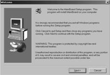
The support software CD-ROM disc loads automatically under Windows 98. When you
insert the CD-ROM disc in the system CD-ROM drive the Autorun feature will
automatically bring up the install screen. The screen has three buttons on it,
Setup, Browse CD and Exit. See the following screen illustration.
When you click on the Setup button the software installation program will run and you can select what kind of installation you want to do, as explained later in this section.
The Browse CD button is the standard Windows command that allows you to examine the contents of the disc using the Windows 98 file browsing interface.
The Exit button closes the Auto Setup window. To run the program again, reinsert the CD-ROM disc in the drive or click on AutoRun in the context sensitive menu for the CD-ROM drive icon in a file browser window.
To install support software for the system board follow this procedure:
Click on the Setup button. The install program will load and display the following screen. Click the Next button.
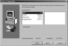
Select the items that you want to setup by clicking on it (the default options
are recommended). Click the Next
button to proceed.
The support software will automatically install.
Once any of the installation procedures start, software is automatically installed in sequence. You will need to follow the onscreen instructions, confirm commands and allow the computer to restart as few times as is needed to complete installing whatever software you selected to install. When the process is finished, all the support software will be installed and working.
There are some utilities that you have to manually install if you need, check to the above section.
|
