Ether-FSH2400R/RS
Remote Management Application
User Guide
The Remote Control Protocol (RCP) is a simple control protocol proposed to enhance the functionalities of OvisLink's dumb Layer 2 switches by software. The Remote Management Application, is a Window-based software package that implements RCP functions at the management host side. The Remote Management Application gives network administrators the ability to configure and monitor dumb layer 2 switches like intelligent switches.
To use Remote Management Application, it is necessary that your system include the following components:
|
Hardware | |
|
Pentium class processor |
|
|
32 MB RAM |
|
|
Software | |
|
Windows® 98 (Second Edition for non-English operating systems), ME, NT 4.0 Service Pack 6, 2000, XP |
|
|
WinPCap 3.0 |
After you install Management Application on your computer, an application folder is placed on the desktop.
To start Management Application, do the following:
Double-click the ![]() icon on the desktop to start the Remote
Management program.
icon on the desktop to start the Remote
Management program.
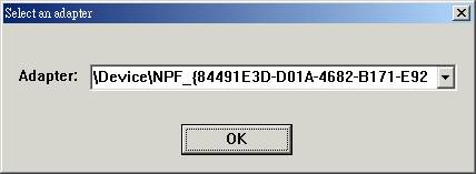
You can select one network adapter. The adapters are displayed in the combo box.
The Management Application shows one switch's information at one time. So, you must select a switch using the combo-box witch displayed switches discovered in the network.
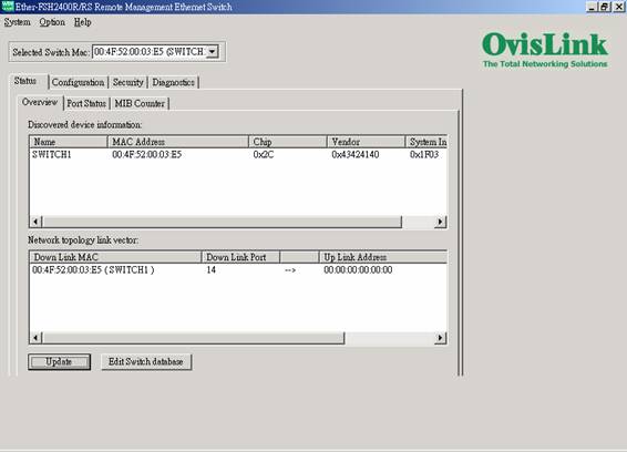
l Discovered device information:
List all switches founded in the network. You can named the switches by double-click the item in the list box.
l Network topology link vector:
Show the link status of the switches.
l Update button
If you want to know the newest switch's information of the network, press the Update button.
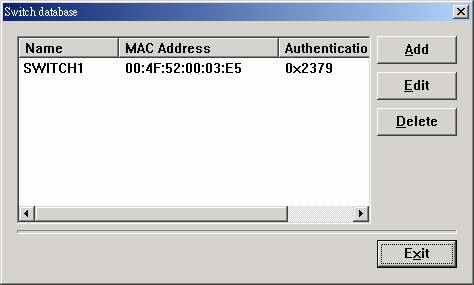
l Switch database button
You can view the switch database. The database dialog box displays switch's name, mac address and authentication Key.
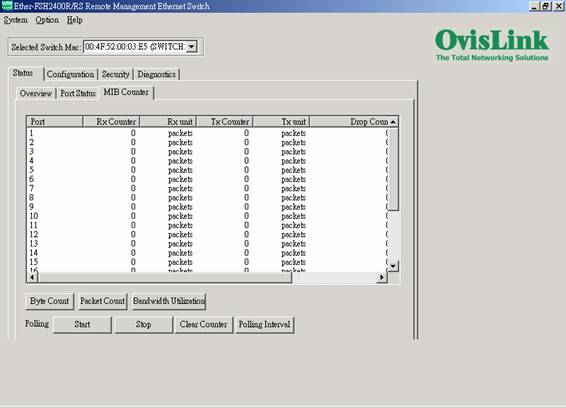
You can view the MIB counter about the RX, TX and Diagnostic Counter. Click the Diagnostic Counter column header, there are three object you can select, such as Drop count, CRC error count and Collision count.
l Byte Count Button
You can set the unit of the RX and TC counter to Byte count.
l Packet Count Button
You can set the unit of the RX and TC counter to Packet count.
l Bandwidth Utilization Button
Displayed the per-port traffic utilization. It will set the TX, RX and Diagnostic Counter to utilization mode.
l About Polling
You can start counter by click the Start button, and click the Stop Button to stop. Clear Counter button is use to clear all MIB counters, it will reset the counters to 0.
Polling interval button is used to set the time interval for the frequency of queried.
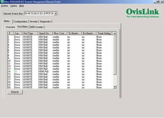
You can view the port status of the switch that you select. The list box will show the status of port1, port2.,and port26. The port status includes port type, enabled status, link status, speed duplex, flow control, Tx bandwidth control, Rx bandwidth control, and trunk setting status.
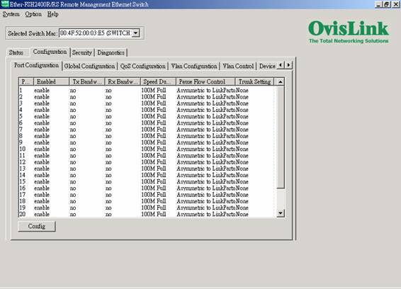
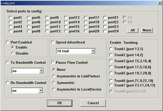
Press the Config button, and you will see a dialog like follows. Put the check in the item you want to configure.
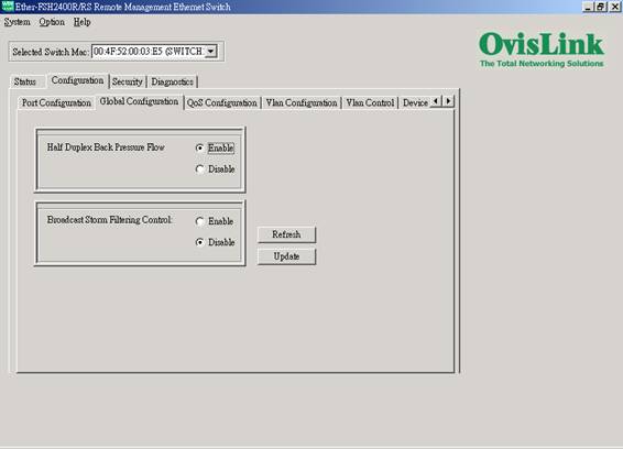
Global Configuration is used to configure the global port control registers. Press the Refresh button to read the status of the registers. Press the Update button to set the registers as shown in this frame.
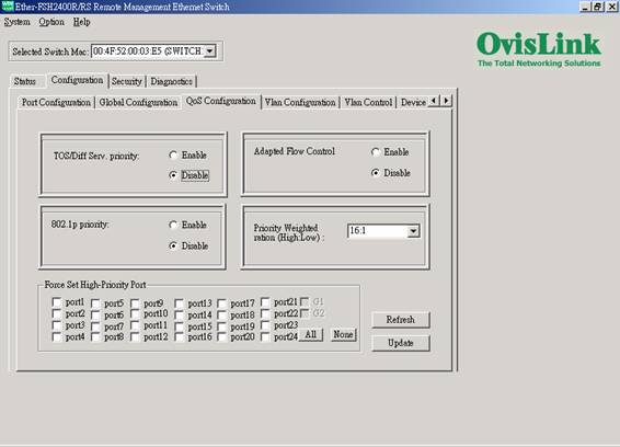
Qos Configuration is used to configure the Qos control registers. Press the Refresh button to read the status of the registers. Press the Update button to set the registers.
This page is used to configure the vlan table registers.
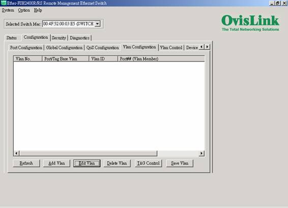
l Refresh button
Read the vlan table registers.
l Config button
Setting a vlan.
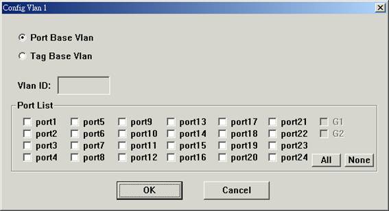
Select one valn in the list box or double-click the vlan you want to config, it will pop up a dialog like follows:
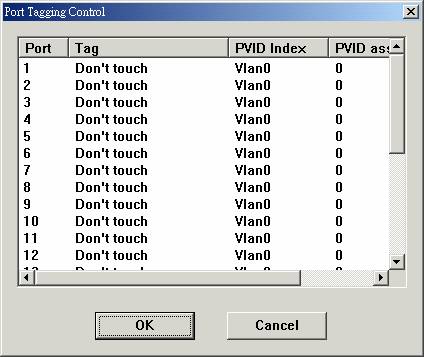
l Port Tagging Control button
Press this button you will see a dialog like follows. To configure a port, please double-click the port you want to configure.
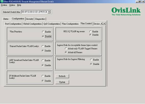
Setting VLAN Control Registers.
Press the Refresh button to read the vlan control registers. Press the Update button to set the registers, and it will set all vlan control registers to the selection.
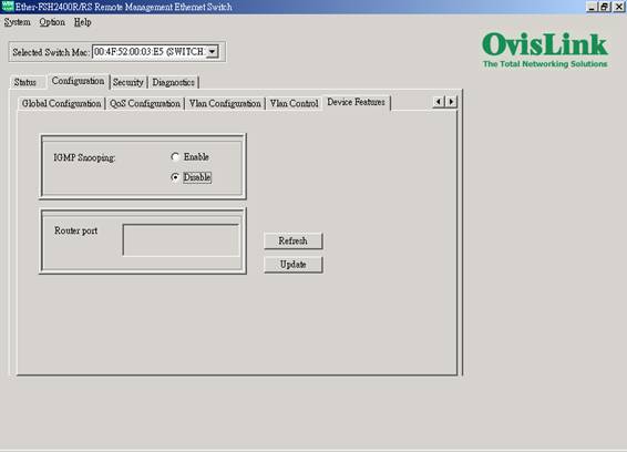
Setting IGMP Snooping Control register and IP Multicast Router Port Discovery register. Router port report will show the IP multicast Router port list. Press the Refresh button to read the register. Press the Update button to set the registers, and it will set the register to the selection.
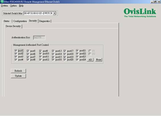
This page displays the authentication key of the switch, and the RCP Management Security Mask Configuration. The authentication key is readable in this version. You can press the Refresh button to read the register, and press the Update button to set the registers, and it will set the register to your selection.
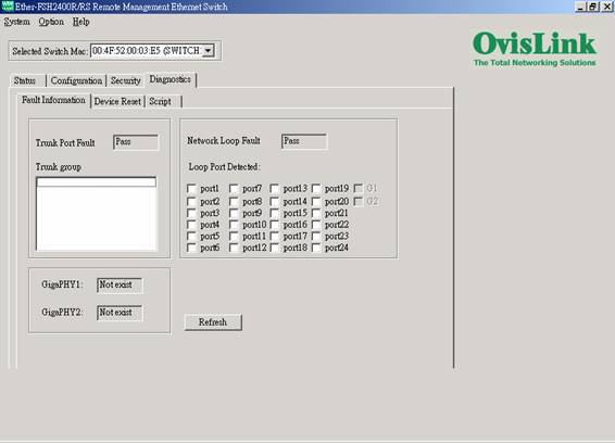
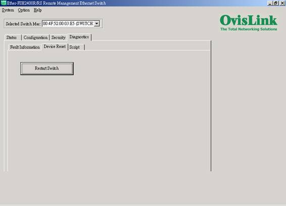
Show some information likes Trunk Port Fault, Network Loop Fault Test, and Gigabit PHY existence report for Gigabit Port G1G2 (only Ether-FSH2402GT provide with G1G2 Gigabit Ports).
The software reset will reset the system to the initial state. The MAC table and VLAN table data will be kept. All the current user configured values of internal registers will be kept. The EEPROM download will NOT be done again. But the system will restart the process of Auto Negotiation . The hardware reset will reset all the system at a initial state like the process of power on hardware reset.
You can save or load the configuration to a file. T
To save a file, do one of the following:
In the Browser, click System | Save Configuration .
To load a file, do one of the following:
In the Browser, click System | Load Configuration .
In the Open File dialog box, select a ".rrcp" file and click Load.
In the Setting Active Switch dialog box, select a switch you want to set, and click OK.
You can set some system options.
Hello polling
The Management Application send hello packet to switches in the network, and this function is used to set the generation interval of hello control frame. To reduce unnecessary control frame traffic, a value of 2 seconds is recommended.
Counter polling
The Management Application send packet to read the counter registers, and this function is used to set the generation interval of these packets. To reduce unnecessary control frame traffic, a value of 6 seconds is recommended.
|
