Welcome to F/A-18 Korea 1.2 Demo. This document provides a Quick Start guide as well as a partial list of keyboard commands to help you in evaluating the simulation. GSC has gone to great lengths to obtain absolutely accurate information on all aspects of the F/A-18 avionic subsystem, as well as to provide an extremely high-fidelity flight model.
The simulation is extremely accurate and detailed. Although there is no way to introduce all the features of the actual product in this small demonstration version, it will serve to give you a taste of what's available.
* High-fidelity simulation of the Navy and Marine F/A-18C Hornet. Incredibly realistic avionics and weapon systems modeling.
* Spectacular graphics using your 3d graphics accelerator card. Supports OpenGLT compatible video cards.
* Powerful mission editor. You can actually program each aircraft to behave as you wish. Unlimited variety!
* 260 page manual written by a USMCR F/A-18 Pilot.
* Multi-media training classroom includes over 100 minutes of instructional voice with animated diagrams or game replay footage.
* Six network missions for up to four players. No additional purchase required for network "join" client.
Required: Pentium II or compatible, 233 MHz, 64 MB RAM, 8x CD-ROM drive, 50 MB free hard disk space, 3D graphics accelerator (Voodoo 2 or newer, or OpenGL compatible with at least 8MB video memory), internet connection for multi-player. Windows 95/98/ME or 2000. Does not support Windows NT 4.0.
Recommended: Pentium II or compatible, 400 MHz, 128 MB RAM, 16x CD-ROM drive, graphics accelerator with 16 MB video memory or more. Joystick.
The F/A-18 Korea 1.2 update provides support for current generation Windows computer systems under 98/ME/2000. The new version supports both OpenGL and Glide (Voodoo), allowing 3D graphics acceleration on many video chipsets. It also supports Direct Input, which enables current generation USB joystick support. Windows NT 4.0 is no longer supported since DirectX 7 is now required.
F/A-18 Korea 1.2 supports current-generation 3D graphic video cards via OpenGL, as well as 3dfx Voodoo (Glide). To better take advantage of the capabilities of these new cards, graphic detail has been enhanced through higher resolution terrain textures, better atmospherics, and volumetric clouds. Screen resolutions of up to 1024 x 768 are supported. Texture maps for OpenGL are TARGA (.tga) format files, and may be modified with an image editor - CHANGING TEXTURE FILES IS UNSUPPORTED.
OpenGL is a graphics method that is supported by nearly all 3D video cards, while Glide is supported only on cards using the 3dfx Voodoo chipset. The user can choose the graphics acceleration method within the game "Cockpit Interface Screen" under "Settings:Preferences". If a 3dfx Voodoo 1 or 2 is installed, choose "3Dfx Voodoo (Glide)". If a Voodoo 3, 4, or 5 (3000, 4000, 5000 series) card is used, and if the latest 3dfx drivers are installed, then both "OpenGL" and "3Dfx Voodoo (Glide)" work. If any problems occur with a 3dfx card using OpenGL, simply select the Glide option. All other cards (including ATI Rage 128, ATI Radeon, nVidia TNT2, nVidia GE Force) cards must utilize OpenGL. If no 3D acceleration is available, neither graphic acceleration option should be checked. This produces non-texture mapped, flat-shaded graphics (not recommended.)
If OpenGL is selected and the frame rate experienced during flight is EXTREMELY slow, this means that OpenGL is not accelerated. Make sure that your video card supports OpenGL. If more that one monitor is connected, disable one of the displays in the "Displays" control panel. Most OpenGL drivers do not accelerate with two monitors attached. If your frame rate seems too slow, but yet playable, try reducing "Flight window resolution" under "Settings:Preferences".
Version 1.2 supports Direct Input to read Joystick devices. If more than one joystick is connected, the game always uses the "Primary" joystick. Under "Settings:Preferences" select either "Joystick" or "Programmable Joystick". "Joystick" is the recommended setting, as it allows the buttons to be reassigned within the game. To program joystick buttons, make sure "Joystick" is selected, and that the stick is properly attached and calibrated using the "Gaming Option" or "Joystick" control panel. Begin a mission. When that mission is loaded, press "Ctrl-J" to enter button-program mode. While in program mode, press and hold a button on the joystick, press and release a key on the keyboard, release the joystick button. Program other buttons as desired. Joystick button programming is automatically retained in the "Korea.cfg" configuration file along with other user settings. Note that the left and right mouse buttons"Programmable Joystick" requires an external button programming method as supplied by joystick manufacturers. Under this setting, the game does not attempt to read the buttons, but relies on external software to send keystrokes in response to button presses.
Given the advanced nature of this simulation, we have provided a fully functional avionics and weapons suite on which to base your evaluation. This demo provides all the functionality of the actual product, with the following exceptions:
* Operations are limited to a single mission in the Korean theater
* Training classroom and printed documentation are not available
* Network play is not available
* Replays made with the retail version are not compatible with replays made using this demo.
* This demo automatically plays one of the saved films in the 'Replays' folder if left idle for 30 seconds. These replays may also be viewed through the Replay Room.
The following pages are excerpted from the F/A-18 Korea Users Manual.
This chapter will get you started with loading and running F/A-18 Korea.
After installing F/A-18 Korea Demo, it is highly recommended that you spend a minute or two configuring the software to run at its best on your specific system. The Options for adjusting how F/A-18 Korea runs are displayed in the Enter Cockpit screen on the Digital Display Indicator (DDI). Refer to Chapter 3 for further details.
Can't wait to get airborne? The quick-start guide is designed to get you into the air quickly, and provide you with some of the very basic keystrokes necessary to operate the simulation. The keystrokes addressed here will allow you to 313u2024d taxi and takeoff. For further elaboration on any specific aspect of flight (including firing air-to-air or air-to-ground weapons), please refer to that section in this manual, or use the training section of the Ready Room.
To start the engines press the "+" key. The engines will spool up, to monitor the start press the "e" key to bring up the Engine monitoring page on the Left DDI. By default, the engine page should already be selected and visible after entering the simulation.
Before taxiing, request clearance to taxi from Ground Control. Taxi the aircraft using the throttle and the wheel brakes by pressing the following keys:
Request clearance from ground - SHIFT "G."
Throttle - increase engine thrust "+", decrease engine thrust "-".
Wheel brakes - "spacebar" (applies brakes while it is held down).
Parking brake - When stopped - "spacebar" (toggle on/off).
Before getting on the runway for takeoff, request clearance for takeoff from the tower. When cleared, taxi on the runway and select afterburners. Pull back on the stick (rotate) the aircraft at about 145 knots. Set between 10 - 15 degrees nose up on the HUD. When safely airborne, raise the landing gear.
Request clearance from tower SHIFT "T".
Afterburners BACKSPACE or DELETE (more than once)
Landing Gear "G"
 Welcome to the Ready Room! The Ready Room is so named because that is
where pilots gather to get "ready" to go flying. The Ready Room is a central place for
squadron members to meet, plan, brief and de-brief their missions. Intelligence specialists will also use the
Ready Room to conduct briefings to aircrew members about such topics as threats
and pertinent target information. Any
information concerning squadron operations is also disseminated in the Ready
Room. Basically, if anything is going on
- the Ready Room is the place to be (other than in a jet!).
Welcome to the Ready Room! The Ready Room is so named because that is
where pilots gather to get "ready" to go flying. The Ready Room is a central place for
squadron members to meet, plan, brief and de-brief their missions. Intelligence specialists will also use the
Ready Room to conduct briefings to aircrew members about such topics as threats
and pertinent target information. Any
information concerning squadron operations is also disseminated in the Ready
Room. Basically, if anything is going on
- the Ready Room is the place to be (other than in a jet!).
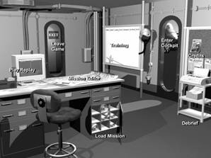
F/A-18 Korea utilizes the concept of a Ready Room for its primary interface. The Ready Room is the main screen from which all actions are selected. From the Ready Room screen you can select:
 Mission Editor
Enter Cockpit
Load
Play replay
Training
Debrief
Credits
Leave Game
F/A-18 Korea is designed to be primarily played in the career mode. The career mode makes you an F/A-18 driver from either the Navy or Marine Corps. You also have the ability to choose which squadron you will fly with. To start your career as an F/A-18 pilot, choose Enter Cockpit from the Ready Room.
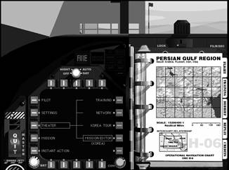
All flight related functions are available from the Cockpit. From here the user may choose functions such as, change game preferences, choose missions, and fly the aircraft. The Cockpit is divided into three primary areas:
|
DDI: |
Monochrome CRT with buttons surrounding it. Clicking these buttons allows the user to navigate through the various menu options and selections. |
|
Kneepad: |
Small rectangular note pad
to the right of the DDI. The kneepad contains "pages" of
information and/or buttons used to select various options. |
|
Tabs: |
Positioned on the right edge of the kneepad. The tabs allow the user to navigate to different areas of the interface, such as the classroom, film library, or debrief area. |
Using the interface is as simple as clicking (with the mouse) on any DDI button or any active button or field on the Kneepad. For example: To change the monitor resolution, click on the Settings DDI button and then click on the Preferences button. The monitor resolutions appear in the lower right-hand corner of the kneepad. Click on the desired resolution.
The kneepad tabs are used to navigate to other areas of the interface. The five tabs are located to the right side of the kneepad:
|
Flight: |
Provides a shortcut directly to the Preflight page using current theater and mission settings. |
|
Training: |
Goes to the Training Classroom which provides extensive online tutorial and video sequences. |
|
Debrief: |
Shows the debriefing for the last mission flown, and allows replays to be saved. |
|
Replay: |
Goes to the Replay area, where previously saved videos can be recalled and viewed. |
|
Squads: |
Allows the user to select a squadron to join. The selected squadron insignia is displayed on the user's vertical stabilizers. |
The Pilot menu on the left side of the DDI displays the following options on the right side of the DDI:
|
Dossier: |
Clicking on Dossier brings up the kneepad page containing the pilot's active duty history. Name, rank, serial number, picture ID, callsign, score, and personal notes are stored here. Eight pilot positions are available so that multiple pilots may exist. |
|
Kills: |
This is a list of the pilot's kills for each target type, along with the score value of each type. At the bottom of the page is the total score. |
|
Awards: |
This page displays ribbons awarded for successful Tour-of-Duty missions. |
|
Top |
This is a list of the ten highest-scoring careers. |
|
Reset Pilot: |
Deletes the current pilot and creates a new one at the beginning of a career. Resetting the pilot is required when the pilot dies, or when the pilot completes a career and retires. |
Settings are altered by clicking on Settings, located on the left side of the DDI. The following options are available through this selection:
|
Detail: |
This is where the various graphic effects and controls are set. Lowering detail and using fewer graphic effects improves performance. Effects of certain graphic changes on the environment are displayed in the picture window at the bottom of the page. |
|
Difficulty: |
This page is used to inhibit or completely override damage to the pilot's aircraft. Enemy skill levels may also be adjusted. |
|
Preferences: |
This is where controls for sounds, flight and video mode are located. Two frame rates are available; 10 and 20 frames per second. Faster computers can easily support the 20 FPS option, whereas slower computers may require the lower setting |
|
Network: |
This page is used to select network protocol for network missions. See the Multi-player section for details |
|
Set Defaults: |
Current settings are saved as defaults |
There are three theaters of operation:
|
Training: |
This theater depicts a
training area in beautiful |
|
Network: |
This theater, a joint
military installation in |
|
|
These Tour-of-duty missions advance the pilot's career |
|
Mission Editor: |
Select this theater to load and fly a mission created with the Mission Editor or to enter the Mission Editor |
Choosing a theater displays a map page on the kneepad. Clicking within the map region zooms the map. The map may then be scrolled in any direction up to its geographical limits by pressing and holding the mouse button while dragging the mouse within the map window. Clicking in the map legend area zooms out.
The
The kneepad displays the briefing for the selected mission. Study the briefing before flying, as it describes the objective for the mission. Click on the curled page corner to view additional briefing information.
Instant action may be selected to fly any of the available tour missions. All tour missions appear in a scrolling list. Instant Action missions do not effect the pilot's health, score or career. Note that Instant Action is not available in the demo.
The Preflight option is available from the
|
Fly: |
Initiates the current mission with the selected loadout. |
|
Air-To-Air: |
Recalls a previously stored default A/A weapon loadout. Holding the SHIFT key down while pressing this button saves the currently chosen custom loadout as the default A/A loadout. |
|
Air-to-Ground: |
Recalls the current default A/G weapon loadout. Holding the SHIFT key down while pressing this button saves the currently chosen custom loadout as the default A/G loadout. |
|
Cancel: |
Returns to the previous page. |
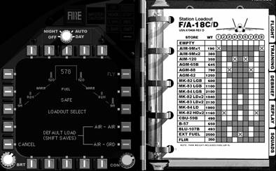
Loadouts are selected for each mission by filling out the form on the kneepad. Weapons are loaded by clicking on the desired spaces, one selection for each aircraft station. Stations which cannot accept a particular ordnance are gray and cannot be selected.
After loadout, click on Fly to begin the mission. Loading the mission may take several seconds. Training and network missions are restarted by pressing "ESC". Pressing "SHIFT ESC" aborts the current mission and enters the debrief room.
The current mission automatically ends under any of following circumstances:
Pilot dies.
Pilot bails out.
Pilot ditches.
Pilot spools down the engines below 60% (turns them off) with weight on wheels.
 The Classroom provides access to an aviation
curriculum which teaches the required skills and systems knowledge necessary to
adequately operate an F/A-18 Hornet. Included are around 60 lessons, divided into six basic
topics. The topics correspond to the six training missions. The lessons are
comprised of video replays with overlaid voice instruction or animated
chalkboard illustrations with overlaid voice instruction. Begin a lesson by
first clicking on the desired topic, then by clicking on the desired lesson. At
any time the related training mission may be flown by clicking on the airplane
at the bottom of the screen. Click on the kneepad to return to the
Cockpit.
The Classroom provides access to an aviation
curriculum which teaches the required skills and systems knowledge necessary to
adequately operate an F/A-18 Hornet. Included are around 60 lessons, divided into six basic
topics. The topics correspond to the six training missions. The lessons are
comprised of video replays with overlaid voice instruction or animated
chalkboard illustrations with overlaid voice instruction. Begin a lesson by
first clicking on the desired topic, then by clicking on the desired lesson. At
any time the related training mission may be flown by clicking on the airplane
at the bottom of the screen. Click on the kneepad to return to the
Cockpit.
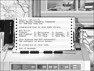 Debriefing Room
 After flight, the pilot enters the Debriefing Room, where a detailed report of mission activity prints (to the screen). Points for all destroyed targets are awarded at this time. If sufficient points for rank promotion are accumulated, the pilot is informed of the new rank on "printout".
The Debriefing area is accessed from the Ready Room or from the Cockpit by pressing the Debrief tab on the Kneepad. To return to the Ready Room, click on the kneepad to the right of the printer.
The Debrief Printout contains information on the number and type of targets killed along with the overall success of the mission. The printout can be advanced at anytime by clicking on the paper itself.
 Saving
Replays
Saving
ReplaysTo the left of the printer is a videotape. Clicking on this tape brings up a Replay Save Dialog which resembles a videotape. A file name is entered, along with some optional notes about the replay. Once a replay has been saved, the videotape no longer appears behind the printer.
The Film Library provides an interface from which videotapes may be "viewed". Videotapes are either saved in the Debriefing area, or manually copied to the "Replays" directory on the hard disk. The Film Library is accessed from the Ready Room by clicking on the computer screen. The DOS computer screen is divided into three areas:
|
Replay List: |
This area provides a scrollable list of all replays in the replay directory. Pressing "ENTER" with a replay selected on the scrolling list runs the replay. |
|
Notes: |
Notes saved with the selected replay appear here. |
|
Search: |
Type characters to navigate the list. |
F/A-18 Korea replays are small, highly efficient files which contain everything that happened during flight. Although view positions are stored internally for playback just as they were recorded, view playback may be overridden anytime during playback, allowing manual view control, by pressing "CONTROL U".
All replays are stored in a directory named "Replays" within the main application directory. Adding and removing replay files to this directory updates the replay list in the Replay Room.
Click the kneepad image to exit the Film Library and return to the Ready Room.
The following list shows the points required to achieve promotion:
Rank |
Required score |
|
Ensign / 2nd Lt. |
0 |
|
Lieutenant J.G. / 1st Lt. |
5,000 |
|
Lieutenant / Captain |
12,000 |
|
Lieutenant Commander / Major |
25,000 |
|
Commander / Lt. Colonel |
45,000 |
|
Captain / Colonel |
75,000 |
Score is awarded for each target killed during a mission. Point values depend on the target. In addition to points for enemy kills, bonus points are awarded as follows:
|
+4000 |
Points for successfully completing the mission objective. |
|
+2500 |
Points for safely landing the aircraft after a successful mission. |
|
-2500 |
Points for failing to land (or ditch) the aircraft in friendly controlled territory (Red Zone). |
F/A-18 Korea accurately reproduces all of the major components and functionality of the real F/A-18's avionics suite. This section will introduce the cockpit layout and discuss basic flight instrumentation and symbology. To see the normal cockpit view press the "1" key. To look down at the rest of the forward instrument panel, press the "2" key.
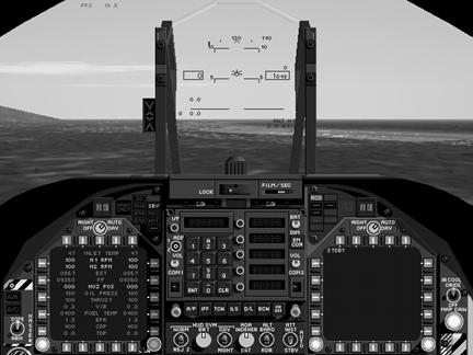 |
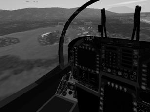
Once in the cockpit you'll see an "out the window" front view looking over the top of the instrument panel. This is the normal cockpit view. It is invoked by pressing the "1" key. Visible in this view is the HUD, and 2 CRT screens. This is the default cockpit view. This view includes necessary access to both weapon and sensor controlling CRT screens and the primary flight instrument, the HUD. There are also other important indicator lights found in the normal cockpit view that you will need to become familiar with in order to fly the F/A-18 Hornet.
The Head's Up Display or HUD is your primary flight instrument. It tells the pilot the attitude of the aircraft in relation to the horizon. The HUD also provides the pilot with important weapon information, but that aspect of the HUD will be covered in the A/G and A/A chapters.
The little aircraft symbol or Velocity Vector (VV) indicates where the aircraft is going. If the VV is on the horizon (0o pitch attitude) then the F/A-18 is straight and level, not climbing and not descending. If the VV is raised to 10o nose up, then the F/A-18 is in a 10o climb. Because the VV is representing the actual flight path of the aircraft controlling pitch and roll attitude is as simple as placing the VV where you need to go.
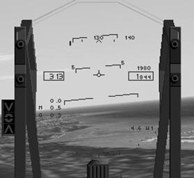 The pitch ladder provides the pilot with a reference for climbs
and descents. It ranges from 0o
(nose level) to +/- 90o (nose up or nose down). The scale is graduated to every 5o
of pitch angle. The nose down or
negative pitch horizon lines are segmented for ease of identification.
The pitch ladder provides the pilot with a reference for climbs
and descents. It ranges from 0o
(nose level) to +/- 90o (nose up or nose down). The scale is graduated to every 5o
of pitch angle. The nose down or
negative pitch horizon lines are segmented for ease of identification.
The airspeed box is on the left hand side of the HUD and indicates calibrated airspeed in knots (Nautical miles per hour). Calibrated airspeed is indicated airspeed corrected for air density and Instrument error.
The altitude box is on the right-hand side and indicates current aircraft altitude. There are two separate modes of altitude display. The default mode is barometric altitude display. This mode displays current aircraft barometric altitude, measured in feet, from sea level. This is also called MSL altitude or Mean Sea Level altitude because it is always measured from the MSL datum. This mode is utilized the most while flying the F/A-18.
The second mode displays the current radar altitude or Above Ground Level (AGL) altitude in feet, measured from the ground directly underneath the F/A-18. It is indicated by an "R" off to the right side of the altitude box when it is active. It is only operational to 5,000 AGL. Only when the aircraft is flying over the sea will the two always be exactly the same (or if the terrain you are flying over is at sea level). To select the radar altimeter mode of the altitude readout box, press CONTROL "a". This cycles between the two modes. This mode should be used when operating the F/A-18 in close proximity to the ground. This is especially important when the ground is significantly higher than mean sea level.
Across the top of the HUD is the heading tape. This tape scrolls to display current aircraft magnetic heading. The current heading is always in the center of the tape HUD display as indicated by the small arrow called the heading caret. To fly the aircraft on a specific heading, turn and place the desired heading directly above the heading caret. Headings are displayed every 10o from 0o to 359o magnetic.
The angle of attack (AOA) indicator is located directly below the airspeed box and displays current aircraft AOA. The AOA angle is measuring the angle between the relative wind and the mean chord of the F/A-18's wing. This is pictorially represented on the HUD by the angle between the waterline symbol (when it is present) and the VV or actual flight path of the aircraft.
Mach number is below the AOA indicator and it displays the current aircraft speed as a percentage of the speed of sound (or Mach number). Mach is around 662 knots on a standard day and varies with air temperature and density.
Aircraft instantaneous "g" meter is located below the mach number readout and displays current aircraft acceleration as a multiple of earth's gravity. 2 g acceleration is equal to two times the pull of earth's gravity, 3 g equals three times, etc. The F/A-18 Hornet's acceleration limit is 8.5 g's. Any more than this risks the possibility of structural damage to the airframe.
The waterline symbol is a fixed representation of the aircraft's centerline, or nose position. It is visible only when the landing are down to aid the pilot in maintaining acceptable landing AOA.
The HUD can be adjusted to better suit your needs while flying. The brightness can be adjusted if it is too bright or hard to see. To change the brightness press CONTROL "b". You also have the option of removing some of the information on the HUD to make it less "cluttered". To reduce the amount of information on the HUD, cycle through the displays by pressing the HUD clutter reject key CONTROL "c". If you desire to turn the HUD off completely, you can do so by pressing the CONTROL "h" key. To turn the HUD back on, press CONTROL "h" a second time.
The left and right Digital Display Indicators (DDI) are the two CRT screens visible in the front cockpit view. Both can display only one of several independent sensor, weapon or aircraft system screens. The two are NOT interchangeable though, a specific display will only appear on either the left or the right - not both.
The right DDI is your radar display DDI. It is initialized to the standby radar screen. The word STBY (standby) is in the upper left hand corner of the display. This is letting you know that the radar is currently selected, but is not currently powered up and operating. Also displayed on the right DDI is the Equipment Status Display (ESD). This display is used to determine the "health" of your Hornet. The ESD shows the status of the major systems aboard the aircraft.
The radar is activated by pressing "r".
The ESD is displayed by pressing "d".
The left DDI is primarily your weapons and sensors display. It also displays engine status, which is what it is initialized to when you first enter the cockpit to fly a mission.
The Electro-Optical sensors are cycled through all available by pressing "o".
HARM missile display is viewed by pressing "u".
The engine status page is viewed by pressing "e".
The Stores Management Set (SMS) display is also viewed on the left DDI. The SMS page (display) shows the current aircraft loadout, including the number of the bullets available for the gun and the number of chaff and flares remaining. To see the SMS page, press "s".
The Up Front Control (UFC) is the used by the pilot to interface with pilot relief modes, Identification Friend or Foe (IFF) set, TACAN and ILS navigation systems, and to utilize UHF (Ultra High Frequency) voice radio communications. The UFC is positioned directly below the HUD, in the normal pilot view, to provide the pilot with quick access to its functions while retaining an "out the front window" view. It remains visible when the look down cockpit view is selected. The UFC is divided into 3 major subsections; the scratch pad window, the pilot option fields, and the radio channel indicator.
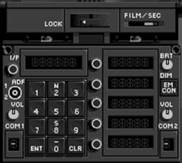 The scratch pad displays the mode selected in
the UFC. The modes which have a display
are; IFF, TACAN, ILS and Auto-pilot.
The scratch pad displays the mode selected in
the UFC. The modes which have a display
are; IFF, TACAN, ILS and Auto-pilot.
The pilot option fields serve as subsets to the primary UFC operating mode selected. If further options are available they are listed there. There is also a process known as "colonization" or colonizing the desired option. This simply means that the specific mode desired will have a colon or ":" in front of it. This is just the means by which the UFC indicates its current operating sub-mode. Therefore, to select something - just colonize it, or in the case of the autopilot, press SHIFT "a" until the colon is in front of the desired option.
 The final subsection of the UFC is the two
radio frequency channel indicators at the bottom of the UFC. These change whenever you broadcast over the
radio to a specific agency. If you are
talking to ground, requesting permission to taxi, a "G" can be seen in the left
frequency indicator box.
The final subsection of the UFC is the two
radio frequency channel indicators at the bottom of the UFC. These change whenever you broadcast over the
radio to a specific agency. If you are
talking to ground, requesting permission to taxi, a "G" can be seen in the left
frequency indicator box.
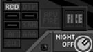
Above the left DDI is a set of caution and warning lights which provide back up indications of aircraft malfunctions or warnings. The left caution and warning lights have the following meanings:
|
FIRE |
Left engine fire is detected. |
|
MAST CAUT |
(Master Caution light) The master caution light comes on, along with a master caution warning tone, whenever an aircraft malfunction is detected. If the malfunction has a warning light associated with it, the light will be on. Otherwise, aircraft system status should be checked on the ESD page (by pressing "d') on the right DDI. |
|
GO |
all systems that are monitored on the ESD are up and operational at this time. |
|
HOOK |
when the light is on, this indicates that the aircraft arresting hook is in the DOWN position. |
|
|
illuminates whenever the speedbrake or the wheel brakes are used. It will also be on whenever the parking brake is set. |
|
L BAR |
Launch bar position indication, when it is on the launch bar is down and connected to the catapult. The aircraft is ready for catapult launch. The launch bar is a small but very strong part of the nose landing gear that is lowered and attached to the catapult shuttle. |
|
NO GO |
whenever a system monitored on the ESD malfunctions, this light will illuminate to tell you to check the ESD page on the right DDI. |
|
STBY |
this light is on whenever the AN/ALQ-126A ECM system is in standby mode. |
|
REC |
this light is on whenever the AN/ALQ-126A ECM system is receiving radar threat signals of significant strength to operate. |
|
XMIT |
indicates that the AN/ALQ-126A ECM system is transmitting (trying to jam) detected enemy radar signals. |
 The right caution and warning lights are
located directly above the right DDI. These lights also provide backup indications of aircraft malfunctions or
warnings. The lights on the right side
have the following meaning:
The right caution and warning lights are
located directly above the right DDI. These lights also provide backup indications of aircraft malfunctions or
warnings. The lights on the right side
have the following meaning:
|
RCDR |
indicates that the HUD recorder is operational and recording. |
|
AI |
part of the RWR set, this light illuminates to indicate that your aircraft is being targeted with radar signals from another aircraft (Airborne Interceptor - AI). |
|
CW |
also associated with the RWR set, this light illuminates whenever your aircraft has detected Continuous Wave (CW) radar energy. |
|
DISP |
illuminates when there are no more dispensables (chaff and flare) left in your aircraft. |
|
SAM |
part of the RWR set, this light comes on to indicate that the RWR has detected radar signals from a Surface- to-Air Missile (SAM) search and track radar. |
|
AAA |
part of the RWR set, this light illuminates when the aircraft is being tracked by Anti-Aircraft Artillery (AAA) radar guidance signals. |
|
APU FIRE |
this light indicates that there is a fire in the Auxiliary Power Unit (APU). |
|
FIRE |
illuminated when a fire in the right engine is detected. |
 |
Below the "out the window" front view is the look down cockpit view. This view is basically the normal cockpit view tilted down. It is invoked by pressing the "2" key. No longer visible in this view is the HUD, but the 2 DDI's and all caution and warning lights are still within view. This view includes both left and right DDI's and the HSD or Horizontal Situation Display. There are other important instruments which are visible only in the cockpit look down view. They include your standby flight instruments and your landing gear, flaps and station selective jettison indicators. Also available only in the look down view is your engine and fuel indicator.
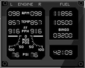 IFEI
IFEIThe AEU-12/A Integrated Fuel / Engine Indicator (IFEI) panel provides the pilot with engine status and fuel information. The following information is available on the IFEI concerning engine status:
|
N2 RPM |
indicates the engine compressor stage's RPM as a percentage. |
|
EGT |
Exhaust Gas Temperature reading displays current low pressure turbine discharge gas temperature, in degrees centigrade. EGT is your best indication of engine thrust. |
|
NOS POS |
engine nozzle position indicator. This number represents a percentage of allowable expansion size of the engine nozzles for all throttle settings. |
|
FF |
fuel flow in pounds per hour indicated for each engine. Total fuel flow is derived by adding both numbers together. |
|
OIL PRESS |
engine oil pressure in PSI. |
In addition to engine performance information, there is fuel quantity information displayed on the IFEI. That information is:
|
TOT FUEL |
combined internal and external (drop tanks, if loaded) fuel amount. Displayed in pounds. |
|
INT FUEL |
total internal fuel amount. |
|
BINGO |
preset low fuel warning amount that indicates you have only enough fuel remaining to reach home base. |
|
TIME |
indicates the flight time reaming at the current time, given fuel flow and fuel quantity remaining. |
 The Horizontal Situation Display (HSD) is
your moving map display. It contains
selectable map scales and images to provide the pilot with current aircraft
location information. The HSD also displays
navigation information from the various F/A-18 nav
systems. There are two modes available
for use by the pilot; navigation and map. Navigation mode does not have a color map background and is
invoked by pressing the "n" key. Navigation mode is also the startup default of the HSD. The map mode does display a color map of the current area
surrounding the aircraft and is invoked by pressing the "m" key. For further information about the HSD, see
chapter 7; Navigation/Radar.
The Horizontal Situation Display (HSD) is
your moving map display. It contains
selectable map scales and images to provide the pilot with current aircraft
location information. The HSD also displays
navigation information from the various F/A-18 nav
systems. There are two modes available
for use by the pilot; navigation and map. Navigation mode does not have a color map background and is
invoked by pressing the "n" key. Navigation mode is also the startup default of the HSD. The map mode does display a color map of the current area
surrounding the aircraft and is invoked by pressing the "m" key. For further information about the HSD, see
chapter 7; Navigation/Radar.
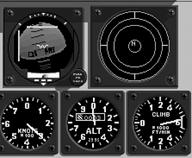
The standby instrument group is located on the lower right side of the cockpit look down view. These are the only conventional instruments found in the F/A-18 cockpit. They utilize pitot and static air ports independent of Air Data Computer (ADC) sources, providing redundant operation should the primary attitude systems fail. The standby instrument group consists of:
|
Standby attitude indicator |
provides the pilot with pitch and roll information. |
|
Turn indicator |
moves to provide the pilot with direction of turn. |
|
ILS localizer and GS needles |
operate when ILS is selected to provide the pilot with glideslope and localizer information to the selected runway. |
|
Waterline symbol |
indicates the aircraft nose position. The waterline symbol is NOT a VV. |
|
Standby airspeed indicator |
provides an alternate means of determining aircraft indicated airspeed, should the primary system fail. It reads in knots. |
|
Standby altimeter |
provides a back up method of determining aircraft barometric altitude should the ADC malfunction. The standby altimeter always reads height above sea level. |
|
Standby VSI |
this instrument provides static pressure Vertical Speed Indicator (VSI) information to the pilot if the INS should fail. The instrument is calibrated in thousands of feet per minute, rate of climb or descent. |
|
RWR scope |
although not a flight instrument, the ALR-67 Radar Warning Receiver (RWR) scope is located in the standby instrument group. For further information about the RWR scope, see chapter 7; Navigation/Radar |
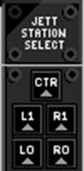
Located immediately to the left of the Engine Monitor Display in look-down cockpit view is the station selective jettison indicator panel. This panel provides advisory information when performing a selective ordnance jettison. To get rid of (or jettison) your undesired under wing stores the lamps will illuminate from top-to-bottom in order. Use "J" to cycle to the desired jettison stations and then press "ENTER" to jettison whatever is located on that rack. Ordnance which is jettisoned is dropped in a safe condition and will not explode upon ground impact.
|
CTR |
Center station selected for Jettison. (selected by first press of "j" key) |
|
LI and RI |
Left #3 (left inboard) and right #7 (right outboard) stations selected for Jettison. |
|
LO and RO |
Left #2 (left outboard) and right #8 (right outboard) stations selected for Jettison. |
The final set of warning and indicator lights located in the cockpit look down view are the landing gear and flap indicator lights. They are located directly below the station selective jettison lamps. They will indicate the gear and flap positions as follows:
|
NOSE |
green indicates that the nose gear is down and locked. If the light is out then the nose gear is up and locked. |
|
LEFT |
green indicates that the left main gear is down and locked. If the light is out then the left main gear is up and locked. |
|
RIGHT |
green indicates that the right main gear is down and locked. If the light is out then the right main gear is up and locked. |
|
HALF / FULL |
both lights are green when the flaps have been commanded to the full down position by pressing the "f" key. If the flaps are commanded up, then both lights will be out |
There are many views available in F/A-18 Korea. They are primarily broken down into three basic types; internal, external and virtual cockpit views. Each view has its own unique use and may be the only method to check a particular display or cockpit instrument.
There are six internal views available (not including the virtual cockpit mode). They are selected by pressing the associated key. Some normal views are momentary in nature and are only presented as long as the invoking key is pressed.
|
Normal cockpit view |
press 1, includes HUD and left and right DDI. Used for all momentary views. |
|
Look down cockpit view |
press 2, all three DDI's, all indicator lamps, and RWR gear and standby instruments (no HUD). Please note that the momentary views are not available from the cockpit look down view (normal cockpit view only). |
|
Momentary look left |
press LEFT ARROW, presents view as long as key is held, shifts view 90o to the left. |
|
Momentary look Right |
press RIGHT ARROW, presents view as long as key is held, shifts view 90o to the right. |
|
Momentary look Up |
press UP ARROW, presents view as long as key is held, shifts view 90o straight up. Also known as "lift vector" view. |
|
Momentary look Back |
press DOWN ARROW, presents view as long as key is held, shifts view 180o to see out the back of the Hornet. Also known as "checking six!" |
There are many external views available. Some external camera positions are centered around your aircraft, while others may be around other aircraft or ground objects, there are even weapon camera views. All external views can be modified by using the following keys:
|
Down Arrow |
tilts view down |
|
Left Arrow |
pans view left |
|
Up Arrow |
tilts view up |
|
Right Arrow |
pans view right |
|
9 key |
moves camera position closer |
|
0 key |
moves camera position away |
|
SHIFT "=" key |
increases optical zoom |
|
SHIFT "-" key |
decreases optical zoom |
The following external camera views are available in F/A-18 Korea:
|
External view |
press 3, camera shows your aircraft. |
|
Radar/EO target view |
press 5, shows you the current designated A/A or A/G target. |
|
Ground/Tower view |
press 6, looks at your aircraft from the airfield tower or from the LSO's platform aboard the carrier. |
|
Weapon external view |
press 7, camera shows your last deployed weapon. |
|
Weapon seeker head view |
press 8, shows you the view from your weapons seeker head. |
|
Aircraft tail #1 |
press SHIFT 1, mounts camera just above your Hornet's tail. This view cannot be modified. (except for optical zoom factor) |
|
Aircraft tail #2 |
press SHIFT 2, same as number 1 except further aft. This view cannot be modified. (except for optical zoom factor) |
|
Wingman external |
press SHIFT 3, shows your wingman. |
|
External friendly aircraft view |
press SHIFT 5, cycles through all friendly aircraft in the mission. |
|
External enemy aircraft view |
press SHIFT 6, cycles through all enemy aircraft in the mission. |
|
External friendly ground unit view |
press SHIFT 7, cycles through all friendly ground units in the mission. |
|
External enemy ground unit view |
press SHIFT 8, cycles through all enemy ground units in the mission. |
|
Fuselage |
press SHIFT 9, shows just aft of cockpit on top of fuselage. Optical zoom modified only. |
|
Right wing |
press SHIFT 0, shows right AIM-9 missile station, optical zoom modified only. |
 Virtual Cockpit
 The final type of view is the virtual cockpit view. This view effectively simulates sitting in the ejection seat of the F/A-18 Hornet. Your view is completely movable through the use of the arrow keys. Use the arrow keys just as you would turn your head (up, down, left and right). You are free to look all around inside the cockpit and outside the canopy. To invoke the virtual cockpit press the "4" key.
While in virtual cockpit mode a HUD display will follow you everywhere you look. You will find this display extremely helpful when your view is slewed off in another direction from the HUD glass. The left and right DDI's can be brought up and displayed while in virtual cockpit mode by pressing CNTRL "I". These DDI's are fully functional and can be used in the exact same way as in normal cockpit view mode. They can be turned off by pressing CNTRL "I" a second time. The view system will "remember" if the DDI displays were on or on and the next time virtual cockpit is selected (within the same mission) the DDI's will return to their last state.
The virtual cockpit has basically two padlock modes you can use. Wingman padlock and missile, target and zone padlock. The padlock view will center the object of interest in the center of the virtual cockpit view and will track that object as it moves. The padlock view can be "re-centered" to a forward view at anytime by pressing the 4 key. A second press of the 4 key will resume the last padlock mode that was used. Press SHIFT 4, to padlock your wingman.
Missile, Target, and zone padlock. Pressing CNTRL will padlock the first of:
The closest inbound missile
The current locked radar/FLIR target
The aircraft closest to the center of the view that is within visual range (5 NM)
The aircraft's master mode determines which mission role you are going to perform in your Hornet. There are three to choose from, Navigation, Air to Ground and Air to Air. This is just a brief introduction as each of these modes has its own chapter later in the manual.
The Navigation (NAV) system is entered automatically when the aircraft is either powered up, or the landing gear are lowered. The Navigation master mode may also be entered at any time by depressing the NAV master mode key "N". The most obvious difference between the NAV master mode and A/A and A/G modes is the HUD symbology. In the NAV master mode the symbology is navigation oriented, while in A/A and A/G modes, symbology is attack oriented.
Air-to-Ground (A/G) master mode includes visual attack capability for delivering conventional and laser-guided bombs, nuclear bombs and for firing the M61 cannon. Also provided are sensor-aided attack capabilities for using the AGM-88 High-speed Anti-Radiation Missile (HARM) and the AGM-65 Maverick, and for using the Forward-Looking Infrared (FLIR).
The Air-to-Air (A/A) master mode is optimized for performance in visual, short-range Air-to-Air combat with M61 cannon and AIM-9 "heat seeking" Sidewinder missiles It also provides effective medium (beyond visual) range attack capability with the Advanced Medium-Range Air-to-Air Missile (AMRAAM) Automatic features which manage weapons and avionics equipment leave the pilot free to concentrate on the tactical situation in a rapidly changing air-to-air environment.
The Classroom provides access to an aviation curriculum which teaches the required skills and systems knowledge necessary to adequately operate an F/A-18 Hornet. Included are around 60 lessons, divided into six basic topics. The topics correspond to the six training missions. The lessons are comprised of video replays with overlaid voice instruction or animated chalkboard illustrations with overlaid voice instruction. Begin a lesson by first clicking on the desired topic, then clicking on the desired lesson. At any time the related training mission may be flown by clicking on the airplane at the bottom of the screen. Click on the kneepad to return to the Cockpit selection screen.
The six topic areas covered in the classroom are:
Takeoff
Landing
Carrier
Navigation
Air to Ground
Air to Air
Key Command
Aircraft
Keypad 4 Aileron Left
Keypad 6 Aileron Right
Keypad 8 Elevator Down
Keypad 5 Elevator Up
Rudder Left
Rudder Right
Increase Thrust
Decrease Thrust
Backspace/Delete Afterburner
Spacebar Speed Brake/Wheel Brakes
G Gear
F Flaps
H Hook
shift D Dump Fuel
shift F Refuel
shift S Service (refuel/rearm)
shift E Eject
D Damage Display
E Engine Display
HUD Options
control A HUD Altitude Toggle
control B HUD Brightness
control C HUD Clutter Reject
control H HUD Hide
Navigation
A Autopilot Toggle
shift A Autopilot Mode Cycle
W Waypoint Cycle
T TACAN Cycle
L ILS Toggle
M Moving Map/Scale
N Navigation/HSI Scale
Radar
R AA/AG Radar Toggle
Q Radar Sub-mode Cycle
B Radar Standby
I IFF Interrogate
Tab Range Decrease
shift Tab Range Increase
shift R ACM Cycle
shift Q AACQ Toggle
control R Silent Mode
Scan Volume
Z Decrease Azimuth
X Decrease Elevation
shift Z Increase Azimuth
shift X Increase Elevation
Target Selection
shift up arrow TDC Up
shift down arrow TDC Down
shift left arrow TDC Left
shift right arrow TDC Right
Designate/Cycle
shift \ Undesignate/TDC Stow
Weapons
S Stores Display
Cycle AA Weapons
Cycle AG Weapons
shift-] CCIP/Auto Toggle
J Jettison Station Select
Release Flare
Release Chaff
C ECM Toggle
Enter/Return Designate/Release
Electro-optical
Q E/O Weapon Cycle
ctrl - Zoom Out
ctrl = Zoom In
ctrl up arrow Slew Up
ctrl down arrow Slew Down
ctrl left arrow Slew Left
ctrl right arrow Slew Right
ctrl \ Target Cycle
Harm
U HARM Display
control \ Target Cycle
Views
Cockpit
Cockpit Lookdown
External
SA/Padlock
Radar/E-O Target
Ground/Tower
Weapon External
Weapon Eye
shift 1 Tail #1
shift 2 Tail #2
shift 3 Wingman External
shift 4 Padlock Wingman
shift 5 Left Stores
shift 6 Centerline
shift 7 Right Stores
shift Left Wing
shift 9 Fuselage
shift 0 Right Wing
View Modifiers
down arrow Look Back/Tilt Down
left arrow Look/Pan Left
up arrow Look/Tilt Up
right arrow Look/Pan Right
Move Camera In
0 Move Camera Out
shift Optical Zoom In
shift - Optical Zoom Out
Simulation Environment
shift escape Exit Flight
control F Fast-time Toggle
Escape Reset Current Mission
P Pause Flight
control E Earlier Time
control L Later Time
control N Night Time
control J Calibrate Joystick
control U Unlock Replay Views
control I Hide Instrumentation
Radio Voice Messaging
shift G Ground Control
shift T Control Tower
shift O Flight Ops
shift C Approach Control
shift L Landing Signal Officer
shift Net Radio Message
Wingman Commands
(shift modifies commands for wingman #2)
Engagement
F1 Help Me
F2 Engage/Protect
F3 Resume
F4 Go Home
Attack Formations
F5 Bracket Left
F6 Bracket Right
F7 Split High
F8 Split Low
Standard Formations
F9 Echelon
F10 Trail
F11 Combat Spread
F12 Lead
|
