![]()
e-drives
Reference notes
TP 800

Order No.: 680074 TP 800 e-drives CD
Description: TP 800 e-drives - Reference notes
Edition: v2.0 (03/04)
Authors: David Hoey, Dan Sandoval, Edward Gasper
Support: Martin Williams, Thomas Häckel, Stefan Grabein, José Leonett, Gerhard Nölle, Hans-Juergen Eberhardt
Layout: David Hoey
© Festo Didactic GmbH &
Internet: www.festo.com/didactic
e-mail: [email protected]
The copying, distribution and utilization of this document as well as the communication of its contents to others without expressed authorization is prohibited. Offenders will be held liable for the payment of damages. All rights reserved, in particular t 13313y2417n he right to carry out patent, utility model or ornamental design registration.
Troubleshooting and maintenance
Construction of the brushless AC servo motor
The resolver, principle of operation
Structure of a typical AC brushless servo drive (velocity mode)
Power stage of servo amplifier
Operating modes of the servo motor
Operating cycles of servo motor
Permanent magnet stepper motor
5 lines wiring of 5-phase stepper motor
Electricity and magnetism |
The basic units of electricity are voltage and current. Voltage is the unit of electrical force. Current is the unit of electrical flow. If a voltage is placed across a conductor such as a wire then electrical current will flow through the wire.
Fig. 1 - Current flows when a voltage is placed across a conductor
By convention, current flows from + to -.
Alternating current (AC) is the type of electricity supplied through power lines. This voltage changes sinusoidally fifty or 60 times per second depending on the country (known as 50 or 60 hertz). Direct current (DC) is the type of electricity that is supplied from a battery. This voltage stays at a constant level.

Fig. 2 - Symbols for AC supply (left) and for DC supply (right)
Electricity and magnetism are related. Every electrical current causes a magnetic field.
Fig. 3 - An electrical current flowing in a wire causes a magnetic field
The size and direction of the magnetic field depends on the size and direction of the electrical current. A large current causes a large magnetic field.
Electromagnets |
A long conductor can be wrapped to form a coil. If a voltage is placed across the coil then the magnetic field from the current is concentrated in one direction. This field lines up with the axis of the coil. The coil can be wrapped around a metal core. The core helps the magnetic field line up.
Fig. 4 - An electromagnet
This setup is called an electromagnet. By convention, the direction of the magnetic field is from North to South. The coil is said to be energized when a voltage is placed across it. When the coil is energized the core is magnetized and acts just like a permanent magnet. When the coil is de-energized the core loses its magnetism.
Electric motors |
If two magnets are placed close together their magnetic fields will interact. They will either attract or repel each other, depending on the direction of their magnetic fields.
Fig. 5 - Opposite magnetic poles will attract each other
Fig. 6 - Similar magnetic poles will repel each other
If the magnets are free to move then they will try to line up with each other. Consider the case of one magnet fixed in position and one free to pivot about its centre. If the magnetic fields are out of line then the pivoted magnet will rotate until the magnetic fields line up.
Fig. 7 - The pivoted magnet will try to rotate
In this example the interaction of magnetic fields caused rotary motion. This is the principle of operation of electric motors. Electric motors convert electrical energy into rotary motion.
Multiplying the voltage applied to a motor by the current it draws gives the electrical input power to the motor in watts (W). Thus a 240V motor which draws 2 amps has an input power of (240 x 2) = 480 W.
P = E x I
If the armature of a motor is coupled to a load then the rotary action of the shaft tends to turn the load. This turning force is called torque (Nm). Multiplying torque and rotational speed gives mechanical power (KW)
![]()
Not all the electrical input power is converted to output power. There are electrical losses due to resistance in the windings and mechanical losses due to friction that reduce the power delivered by the shaft.
There is a relationship between motor speed and torque, and this relationship depends on the type of electric motor being used.
The general symbol for a motor is shown below:

Fig. 8 - General symbol for a motor
DC motors |
DC motors consist of two magnets: a stator and an armature.
The stator is an electromagnet or a permanent magnet. The stator coil windings are called field windings. The stator is fixed in place so that it does not move.
The armature winding is supported by bearings. It is free to rotate. The armature is also known as the rotor.
Fig. 9 - Cutaway of DC motor
The stator creates a magnetic field. When the armature is energized it creates a new magnetic field. These two fields interact and try to line up. For the armature field to line up with the stator field, the armature must rotate.
Fig. 10 - The rotor magnetic field tries to line up with the stator magnetic field, and so the rotor rotates.
Once the armature and stator fields are aligned there is no more tendency for the armature to move. If the voltage energizing the armature is reversed, the armature will turn in order to line up the magnetic fields again.
For the motor to rotate continuously, the polarity of the armature voltage must be reversed every time the stator and rotor fields line up. This is achieved by using a commutator. Carbon brushes make contact with the commutator on the armature and reverse the voltage on the coil just before the magnetic fields line up. A commutator is also called a reversing switch.
Fig. 11 - Reversing of voltage polarity
Types of DC motor |
DC motors have either a permanent magnet stator or a wound stator.
|
Permanent magnet motor |
A permanent magnet is used to provide the constant stator field. This motor has a high starting torque, is suitable for rapid positioning applications, and is physically smaller than other motors.
Fig. 12 - Permanent magnet motor characteristics
|
Shunt motor |
The field winding (shunt winding) and armature are connected in parallel. This configuration gives a relatively constant speed-torque relationship and good speed regulation over wide load ranges. A drawback is the shunt motor's relatively lower starting torque.
Fig. 13 - Shunt motor characteristics
|
Series motor |
The field winding (series winding) and armature are connected in series. This configuration gives high starting torque, but should be avoided in applications where they are likely to lose load. Under no-load conditions this motor can accelerate uncontrollably e.g. Power tools.
Fig. 14 - Series motor characteristics
|
Compound motor |
This is a combination of a shunt motor and series motor. A series winding is connected in series with the armature, and a shunt winding is connected in parallel with the series winding and the armature. The ratio of shunt to field windings gives various torque-speed characteristics that are chosen to suit the application.
Fig. 15 - Compound motor characteristics
Stepper motors |
The stepper motor is a variation of the DC motor.
The stator of the stepper motor consists of many separate windings called poles arranged on "teeth" which are equally spaced around the body of the motor.
The rotor of the stepper motor is a permanent magnet.

Fig. 16 - The rotor in a stepper motor can line up with any of the stator poles
When one of the stator coils is energized, the magnetic fields of the rotor and stator interact and the rotor lines up with that stator coil. If the next stator coil is energized and the first coil is de-energized then the rotor will rotate by an amount equal to the spacing of the stator teeth. The number of poles in the stator governs the number of fixed positions that the rotor can maintain. The more poles the stator has, the more accurately the rotor may be positioned.
Fig. 17 - As each stator pole is energised in turn, the rotor rotates.
The control circuit for a stepper motor determines the speed and sequence in which each stator coil is energized.
Stepper motors are limited to about one horsepower and 2000 rpm.
AC motors |
AC motors consist of a stator and a rotor.
The stator windings are stationary. When an AC voltage is applied to the stator, a magnetic field is produced. The sinusoidal nature of AC combined with the arrangement of the stator windings means that the magnetic field of the stator rotates.
The rotor is a winding supported by bearings and is free to rotate.
AC motors are designed to be powered from either single-phase or poly-phase AC.
The two types of AC motor are the induction motor and the synchronous motor.
Induction motors |
Any conductor placed in a changing magnetic field will have a current induced in it.
When the stator windings are energized with AC, a rotating magnetic field is developed. The rotation speed of this field depends upon the frequency of the supply voltage and the arrangement of the stator windings. This rotating field interacts with the rotor windings and current is induced in the rotor. The induced rotor current creates a new magnetic field. This rotor field tries to line up with the stator field and so the rotor rotates, continually chasing the moving field of the stator winding.
For a current to be induced in the rotor winding, the relative strength of the stator magnetic field must be constantly changing. For this to occur the rotor must turn slower than the rotating stator field. The difference in rotation speeds is called slip. Different induction motors have different amounts of slip. Small electric motors are higher in slip and less frequent than larger motors with lower slip.
The most common type of induction motor is the squirrel cage motor. The rotor conductors are bars of aluminium or copper, separated by a ferromagnetic core. The advantages of the squirrel cage motor are its simplicity, low maintenance, reliability, rapid acceleration to full speed and availability.
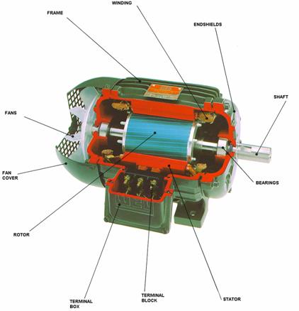
Fig. 18 - Cutaway of induction motor
Fig. 19 - Speed - Torque relationship of an induction motor
|
Split phase motors |
Another type of induction motor is the split-phase motor. This is a single-phase motor. Its stator consists of two windings joined by a capacitor. Such an arrangement allows the motor to be reversed by simply swapping the polarity of the supply windings.
Synchronous motors |
In a synchronous motor, the rotor winding is energized with DC. The magnetic fields of the rotor and the stator interact and try to line up. The rotor rotates at a speed determined by the frequency of the supply current and the arrangement of the stator windings.
Fig. 20 - Cutaway of synchronous motor

Fig. 21 - Speed - Torque relationship of a synchronous motor
A synchronous motor needs help to start. An extra starting winding is used to start the rotor turning. This starting winding is similar to the rotor winding in a squirrel cage motor.
Synchronous motors are used in large, slow-speed machines running at constant speeds. If several motors have to be run at exactly the same speed, synchronous motors could be used.
Motor control systems |
Motors are used to drive loads. The purpose of a motor control system is to control the speed or position of the load. A control system does this by changing the voltage or current that supplies the motor in response to an input signal. Input signals can be manual, such as an operator pressing a button, or from another controller, such as a signal from a PLC.

Fig. 22 - Generic control scheme
Control systems may be open-loop or closed-loop.
Open-loop control |
In an open-loop motor control system, the electrical and mechanical characteristics of the motor being controlled are well known. For example: a certain voltage applied to the motor will produce a certain rotor speed. The open-loop controller is designed to apply a certain voltage or current to the motor in response to a certain input.
Should the characteristic of the motor change then the controller needs to be changed; otherwise there may be errors in controlling the load.
Example: A motor has the following characteristic: an input of 50 volts produces an output of 1000 rpm. A controller designed to run the motor at 1000 rpm supplies 50 volts to the motor. If the weight of the motor load doubles, then the same voltage from the controller might only produce 850 rpm. The change in the mechanical characteristics of the load causes an error between the desired speed and the actual speed.

Fig. 23 - An open-loop controller uses an input signal to drive a motor
The advantage of an open-loop system is its simplicity. The disadvantage is that the controller does not adapt to changes in the motor characteristics, and any errors must be manually corrected.
Sensors |
Controllers can be made more sophisticated if information about the load being controlled is known. Useful information is the speed of the load and its position. Sensors used for measuring these quantities include tachometers, potentiometers and encoders.
|
Tachometers |
The tachometer is used for measuring speed of rotation. It produces a voltage that is proportional to the speed of rotation of its shaft. If the speed of rotation doubles then the voltage output of the tachometer also doubles. Tachometers are also known as tacho-generators.
|
Potentiometers |
The potentiometer is used for measuring angular or linear position. It produces a voltage proportional to its absolute position.
|
Absolute encoders |
The absolute encoder is used for measuring angular position. Depending on its resolution or accuracy, each angular position of the motor shaft will produce a specific output signal.
|
Incremental encoders |
The incremental encoder is used for measuring speed or relative position. The incremental encoder outputs pulses at regular angular intervals of the motor shaft position. When the motor speeds up, the incremental encoder outputs pulses more often. Measuring the frequency at which pulses are produced indicates the speed of the motor. Counting the number of pulses sent by the encoder indicates the distance through which the motor shaft has moved.
Closed-loop control |
In a closed-loop system, sensors measure outputs such as load speed and position. The sensed output signals are compared with the desired output, and the controller supplies a correcting signal.

Fig. 24 - A closed-loop controller uses an input signal and feedback from sensors to drive a motor.
The controller uses the feedback signals to supply a new signal to the motor. This new signal drives the motor towards the desired output.
The advantage of a closed-loop system is the high accuracy that is achievable. The output is continually monitored and controlled. The disadvantage is the complexity of the system, as more components and wiring are needed.
Servo systems |
A servo system is a closed-loop control system.
Servo systems consist of a number of components:
Fig. 25 - A servo system
Servo systems can be adapted to suit the load being controlled. For example: a motor may have to be controlled very quickly or very accurately. Depending on its complexity, the servo system is tuned or compensated to achieve these results.
Servo motors |
A servo system can be constructed by choosing suitable sensors to match the motors in the system. A better method is to use a servo motor. A servo motor is a motor with a feedback sensor already attached. The advantage of using purpose-made servo motors over individual components is that the sensors are guaranteed to be matched to the motor being used, and each sensor is properly coupled to each motor.
Both AC and DC motors are used in servo systems.
The advantages of servo motors are high performance, small sizes and the wide variety of components available. The disadvantages are the higher cost of servo systems, and limitations on performance imposed by controller technology.
DC motor control |
DC motor starting |
When power is first applied to a DC motor, a high current can flow in the armature. To limit the damaging effect this sudden high current can have, power can be applied gradually.

Fig. 26 - DC motor starting
The current-limiting device can be electromechanical, such as timed contactors that switch resistors out of the circuit, or solid state, such as a circuit that electronically limits the current flowing while the motor starts.
DC motor direction control |
The direction of rotation of a DC motor is changed by reversing the relative directions of the armature and stator magnetic fields. For the wound stator motor, this is done by reversing the voltage across the field winding. For the permanent magnet motor, the rotor voltage is reversed. Voltage is reversed using relays or contactors.
Fig. 27 - Simplified direction control circuit
When relay
DC motor speed control |
The speed of a DC motor can be controlled using open-loop or closed-loop techniques.
|
Open-loop techniques |
Open-loop techniques for DC motor speed control include Field Weakening and Armature Resistance control.
Field weakening involves placing a current limiting device such as a variable resistor in series with the field winding. This causes the motor to speed up, so long as the armature voltage remains constant. There is a limit to the amount the field may be weakened.

Fig. 28 Field Weakening
Armature resistance control involves increasing the amount of resistance in the armature circuit. This causes a decrease in motor speed.

Fig. 29 Armature resistance control
|
Closed-loop techniques |
Closed-loop control of DC motor speed involves using a servo system. This allows precise speed control under varying load conditions.

Fig. 30 Closed-loop speed control of a DC motor
DC motor stopping |
The simplest way to stop a DC motor is to remove power and let it coast to a stop. When this method is unsuitable, dynamic braking or mechanical braking methods may be used.
Dynamic braking - If power is removed from the armature winding, a voltage still appears across it. This voltage is induced due to the magnetic field of the shunt winding. If the armature winding is now connected across a resistor, current flows through it. This current flows through the winding in the opposite direction to normal, as if the motor was being reversed. The motor quickly stops.
Fig. 31 Dynamic braking circuit
Dynamic braking is only effective while the motor is turning. As soon as the motor stops, there is no induced current in the armature winding to produce a reversing force.
Mechanical Braking - a mechanical brake can be fitted around the shaft of the motor. This brake is actuated by an electromagnet. The brake may be made to be electrically held open or closed against the force of a return spring. Most brakes are considered "fail safe" i.e. spring applied, with electro-magnetic or hydraulic release.
Stepper motor control |
Stepper motors are controlled electronically by pulses of DC. Stator poles are arranged in groups. The sequence used to energize these poles determines the direction of rotation. Although used mainly in positioning applications, the speed at which pulses are supplied determines the speed of rotation.

Fig. 32 - The sequence used determines the movement of the stepper motor
|
Open-loop techniques |
Stepper motors are usually controlled using an open-loop technique.

Fig. 33 - Open-loop control of a stepper motor
|
Closed-loop techniques |
If the stepper motor is prone to losing steps then an open-loop scheme will not position the motor correctly. In this case a sensor such as an encoder may be used to detect position and improve position control.

Fig. 34 - Closed-loop control of the stepper motor
AC motor control |
AC motor starting |
The simplest way to start an AC motor is to apply full voltage directly to the motor's stator windings. This is the Direct-On-Line (DOL) method.
Fig. 35 - Direct-On-Line starting scheme
The advantage of this technique is its simplicity.
When a motor is started DOL, a larger than normal current will flow. This large current can damage the motor windings and all motors are designed against this today. The sudden electrical shock affects the electrical supply system, and the mechanical shock can damage the load.
In the case where DOL starting is damaging, a form of soft starting is used. This involves limiting the voltage or current during motor start-up. Soft starting techniques include Reduced Voltage and Reduced Current (Star-Delta) starting. Soft starts are typical when motors are coupled to gearboxes etc.
Reduced voltage - The stator winding of a squirrel cage induction motor may be energized through series resistors or reactors. As the rotor begins to turn, the impedance is switched out of the circuit. The switching may be done in steps, and may be manual or automatic. As the impedance is switched out of the circuit, the voltage across the stator winding increases and the motor is gradually brought up to full speed. Reduced voltage starting is also known as Auto Transformer start typical for high inertia loads.
Fig. 36 - Reduced voltage starting
Reduced Current or Star-Delta - In a three-phase squirrel cage motor, the stator consists of three windings. The connection of these windings can be changed using contactors.
Fig. 37 - General arrangement of a star-delta circuit
On start-up, the stator windings are connected in a star or wye configuration. This arrangement causes each coil to be energized with less than the supply voltage. The motor starts up gradually.
Fig. 38 - In the wye or star configuration, contacts s4 and s5 are closed.
Once the rotor is turning, the contactors change over and connect the stator windings in a delta configuration. This arrangement causes each coil to be energized with the full supply voltage. The motor accelerates to full speed. Starting torque in star is 33% and may not be suitable for high inertia starts (very good for fans/pumps). Voltage on start winding is equal to 240V or 415V winding and as torque is proportional to V2 i.e. (240/415)2 = 0.33.

Fig. 39 - In the delta configuration, contacts s1, s2 and s3 are closed.
The advantage of the star starting, delta running technique is that the motor and the supply system are subjected to reduced stresses.
Solid state starters - an alternative to electromechanical star-delta starters is the solid state starter. Semiconductor switches take the place of relays and contactors.
Soft starters - are a reduced voltage/current device that ramps up to the full line voltage. The acceleration is subject to load inertia. Starting torque is limited to "130% + current to" 300%.
AC motor direction control |
To reverse the direction of a single-phase AC motor, the motor must be of the split-phase type. The motor direction is reversed by swapping the polarity of the supply voltage (i.e. swapping the active and neutral conductors).
Fig. 40 - Reversing a split-phase motor
The direction of a three-phase motor can be reversed by swapping two of the three motor supply connections. This swapping is done using contactors.
Fig. 41 - Reversing a three-phase motor
The contactors are mechanically interlocked to ensure that the motor supply connections are switched correctly. Without interlocking there is a chance that mechanical failure in the contactor could cause two of the motor supply connections to short together.
AC motor speed control |
AC motors are widely used for constant speed requirements. The speed of the motor is governed by the speed of the rotating stator field, and this relates directly to the frequency of the electrical supply. Ordinarily, the supply frequency is a constant that is not easily changed. Variable Speed Drives are electronic circuits for changing the supply frequency and voltage to achieve speed control of AC motors.
Variable speed drives |
Variable speed drives (VSDs) are electronic devices used to control the speed of induction motors. VSDs are also known as converters or inverters.
VSDs control speed by changing the frequency and voltage of the motor supply current. In order to maintain the correct magnetizing conditions within the motor, the voltage is also changed.
The circuitry in the VSD changes the AC supply voltage into a DC voltage, and then modifies the DC to form an AC voltage with a new frequency and magnitude. The new AC voltage is slightly distorted, and this distortion can lead to unwanted heating in the motor. This heating can be a problem. According to motor manufacturers, the lifetime of a motor is halved if it is subjected to a continuous over temperature of 10%. More modern inverters have much improved outputs hence less of a problem except where load is close to motor rating.
VSDs are chosen to meet the requirements of the motor and its load. The most important factors to consider when choosing a VSD are the speed range of the motor, the torque required by the load, the inertia of the motor and its load, and the effect the VSD will have on the motor.
The advantages of VSDs are controlled starting currents, speeds, direction and stopping. The disadvantage is the expense of the drive and the care needed to choose the correct drive for an application.
AC motor stopping |
The simplest way to stop an AC motor is to remove power and let it coast to a stop. When this method is unsuitable, mechanical braking is be used.
Mechanical Braking - a mechanical brake can be fitted around the shaft of the motor. This brake is actuated by an electromagnet. The brake may be made to be electrically held open or closed against the force of a return spring. For safety reasons , most brakes are spring applied and air release.
Motor selection |
The following factors need to be considered when selecting a motor:
Speed range - the base speed of the motor is determined by the minimum and maximum required operating speeds.
Allowable speed variation - constant speed at all torque value applications should use a shunt-wound motor. If the accuracy of speed must be less than a few percent then a closed-loop control system using a tachometer will be required.
Torque requirements - starting torque and running torque may need to be considered separately. The speed-torque relationship of the application determines the most economical motor to use. Many applications require constant torque, such as conveyors. Others, such as machine tools, pumps and fans require decreasing torque as speed increases. The peak torque available may be limited by the construction of the motor or the electrical capability of the power supply. The amount of torque available will determine how quickly a load may be accelerated.
Duty cycle - the load may be steady or may vary repetitively or randomly. The amount of time which a motor remains idle may influence motor choice.
Environment - the motor enclosure is selected after considering such factors as ambient temperature, cooling requirements, dust, dirt, hazardous gases etc.
Troubleshooting and maintenance |
Preventive maintenance is probably the best way to avoid problems with electric motors. Regular maintenance can eliminate problems before they start. The manufacturer will supply recommended maintenance intervals and procedures. If the motor does break down, the following list of common problems may provide a useful reference.
(Refer to manuals for Festo motors)
|
DC and AC motors |
Failure to start may be due to a break in the control circuit. Check protection devices such as fuses or circuit breakers. A frozen bearing can cause protection devices to activate. Supply line voltage should also be checked.
Sparking brushes on a commutator can indicate the need for reseating.
Resistors used in control circuits can fail due to overheating. Ventilation should be checked and improved if necessary.
Solid-state devices such as electronic soft starters can fail by opening or short-circuiting. Replacement is usually the only option with electronic devices.
The feedback sensors of closed-loop controllers can be a source of problems. Ensure the feedback path is not short- or open-circuited. Poor mechanical linkage of the sensor to the load can make the control erratic.
Poor electrical connections can cause intermittent faults.
|
Stepper motors |
Stepper motors rely on pulses of DC for control. Control circuitry may be intolerant of power supply variation. Large amounts of ripple on the power supply can upset control signals, leading to erratic operation.
Output drivers can fail if they are open- or short-circuited. Excessive heat is a cause of premature failure. Heat sinks on control circuits should be kept clean and well ventilated.
Do not dismantle stepper motors that have a permanent magnet stator - a loss of torque results.
Servo motors |
Servo motors are motors that can be precisely controlled with respect to speed, position and torque, when incorporated into a special servo control system. Servo motors come in a variety of designs: DC brush, DC brushless and AC brushless. These reference notes describe the AC brushless servo motor.
It is always important to note that while there are motors that have been optimised for servo applications, there is no such thing as a servo motor, per se. A motor does not operate as a servo until it has been integrated into a system with feedback and a power drive unit. The term "servo" is only meaningful and valid when used in a systems context. Although this argument can be dismissed as a semantic issue, it is essential to the full understanding of servo control systems.
|
Principle of operation |
A brushless servo motor consists of a 3-phase stator and a permanent-magnet rotor which rotates at a speed directly proportional to the frequency of the rotating magnetic field through the stator windings (synchronous machine).
When compared to a DC brush motor of equivalent size, the brushless motor, with it's "inside-out" construction generates far more power. This is largely because the superior thermal coupling between the stationery copper windings and the ambient atmosphere makes it easier to remove the heat that is generated in the windings
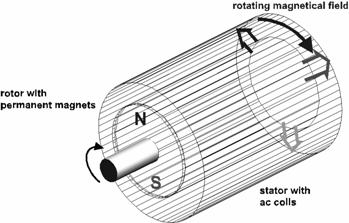
Fig. 42 - Brushless motor design
To generate the rotation, the magnetic flux vectors (U, V, W) have to rotate. This will result in a speed of
![]()
n = motor speed
f = stator frequency
p = number of poles.
This formula shows that the motor speed is proportional to the stator frequency.
The instantaneous motor torque is a determined by the magnitude of the stator current.
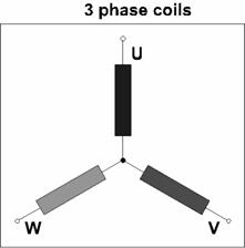
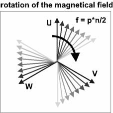
Fig. 43 - The coils of the stator can be controlled in different ways.
|
Block commutation ("DC brushless") |
The phase coils U, V and W are simply switched on and off in sequence (commutated). Each phase is energized for 120°, and switched off for 60°. For the following 120° interval, the current polarity is reversed. The offset between the phases is 120°.
The triggering signals for commutating the phases are generated by three Hall-effect sensors built in the servo motor. Because the resolution of the Hall sensors is coarse, an additional tachometer generator (speed transducer) is required to provide velocity feedback. For applications requiring position control, a position encoder is also required to provide position feedback.

Fig. 44
|
Sine commutation ("AC brushless") |
A sine-shaped current excites the phase coils, U, V and W (instead of being switched completely on or off). As in the block commutation example above, the offset between each phase is 120°.
This commutation approach requires a great deal more sophistication than the previous example. The Hall-effect sensor array used for block commutation makes only 1 pulse for every 120° of rotation, and simple transistor switches can be used to switch the phase coils on and off.
On the other hand, the synthesis of sine shaped phase currents requires the actual position of the rotor to be determined with an accuracy of better than 1°. This requires a resolver to be used as the primary feedback element. Furthermore, the amplifier must be able to modulate the instantaneous phase current magnitude smoothly from zero to maximum, which greatly increases its complexity. A separate circuit in the servo amplifier extracts the velocity and position data from the resolver signal, and re-generates them in a form that emulates an incremental digital encoder, thereby eliminating the need for multiple feedback instruments.
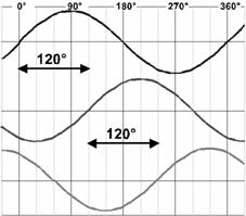
Fig. 45
Construction of the brushless AC servo motor |

Fig. 46 - Cutaway construction of brushless AC servo motor
The resolver, principle of operation |
The resolver is the primary feedback element in AC brushless servo motors. Despite its simplicity, it generates a signal that is precise, repeatable and very rich in information. It is also extremely rugged, capable of withstanding extremes of mechanical shock and temperature (-50°C ... 150°C). Because of the high case temperatures of brushless AC servo motors (up to 140°C/284°F) the resolver is a far better choice than other position sensors like potentiometers or optical encoders.
The resolver is a 3-coil device, consisting of a single rotor coil directly coupled to the motor shaft. This part rotates within the 2-coil stator of the resolver.
The resolver is essentially a rotating transformer. The primary (rotor coil) is excited with a high-frequency AC voltage (carrier). The two secondary (stator) coils are displaced by 90°, resulting in a sine/cosine relationship between the magnitudes of the two coil signals. These signals are processed and converted by the resolver/digital converter (RDC). The RDC has two outputs: commutation data for the amplifier, and velocity/direction in the form of a synthesized incremental encoder signal.
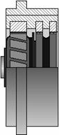
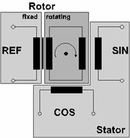
Fig. 47 - Resolver to Digital Converter
The rotor of the resolver is supplied with the reference signal REF.
![]() (Carrier
Frequency)
(Carrier
Frequency)
The feedback signals SIN and
![]() and
and ![]() . (with
. (with ![]() = angle of actual
rotor position).
= angle of actual
rotor position).
In simpler terms, the oscillator of the RD converter excites the rotor with a high frequency carrier, in the 10's of kHz range. This signal is induced in both stator windings, but the magnitude of each stator signal depends on the angle of rotor rotation. Therefore, the induced carrier in both stator windings is amplitude-modulated by the rotational frequency. If the carrier frequency is stripped away from the stator signals, (demodulated) their "envelopes" will resemble a sine wave with a frequency proportional to the rate of rotation. Because both stator coils are displaced by 90°, the two envelopes will have a sine and cosine relationship. The term "quadrature" is used to describe two identical periodic signals that are displaced by 90°. The direction of rotation can be discerned by examining which signal "leads" or "lags" the other. The resolver signals are processed by the circuit shown below:
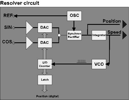
Fig. 48 - The resolver signals are processed by the resolver circuit
Structure of a typical AC brushless servo drive (velocity mode) |
The AC brushless servo drive package (generically known as a servo amplifier) is organized as an outer loop of speed control and an inner loop of current control. The command input is shown below as the speed setpoint, and is a +/- 10V signal, which is a standard command interface format. This speed setpoint is compared with the actual speed in order to generate a current setpoint. The current setpoint, compared to the commutation reference generated by the resolver logic block, is input to the current control loop. The instantaneous stator phase current is generated by using a pulse-width modulation (PWM) switching amplifier for each coil. In this fashion, three AC phase currents, separated by 120° are generated. The magnitude of these currents determine the instantaneous motor torque, which is continuously adjusted in order to keep the motor turning at the velocity commanded by the speed setpoint, regardless of variations in mechanical load. This is known as commanded velocity control mode.
Some drives can be configured to regulate the motor's torque proportionally to the command input, regardless of variations in velocity. This is called commanded torque control mode - (this mode of operation is not represented by the diagram below).
The resolver logic block also synthesizes a 3-channel digital incremental encoder signal, consisting of two quadrature tracks (A and B) and a "12 o'clock" reference pulse, (N). The resolution can be selected, with a typical value of 1000 pulses per revolution (A & B). This "3-channel incremental encoder" signal is the standard feedback interface format to servo positioning controllers (not shown).
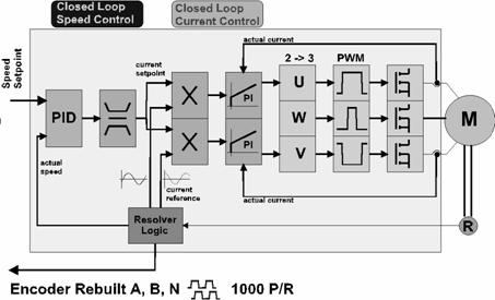
Fig. 49
Power stage of servo amplifier |
A DC bus voltage of approximately 320 VDC is generated directly from the AC powerline with a bank of rectifiers, and is the main power input to the PWM amplifiers. Smaller amplifiers use a single-phase supply, while larger amplifiers are often configured with 3-phase input rectifiers (shown below). The high DC bus voltage allows greater motor power with less current, thereby reducing energy (heat) dissipation in the motor windings and interconnecting cables.
The regeneration circuit recovers the energy generated by the motor when it decelerates (up to a point). Energy exceeding the capability of the regeneration circuit must be dumped into a regeneration load (i.e. braking resistor) to prevent the bus voltage from rising to excessive levels. This could happen, for instance, when large motors decelerate high-inertia tractive loads.
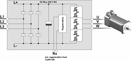
Fig. 50 - Larger amplifiers are often configured with 3-phase input rectifiers
Operating modes of the servo motor |
The servo system delivers energy to a mechanical system as long as the torque vector (M) is in the same direction as the velocity vector (n), such as in quadrants I and III, below. By the same token, when these vectors are signed in opposition, the servo system is absorbing energy (quadrants II and IV). The operation of a traction elevator effectively demonstrates this concept. The motor must do work against gravity to raise the elevator (Q-I), but when the elevator is being lowered, the motor must supply a braking torque to regulate the descent speed (Q-II)
In quadrants II and IV, the motor behaves as a generator, whose energy output is absorbed by the amplifier, which results in an increase of the DC bus voltage. For most amplifiers, if the DC bus voltage increases beyond 115% of nominal, the amplifier will divert the generated energy to an external regeneration load (braking resistor). Such resistors are often found in applications where large tractive loads (i.e. High inertia or heavy vertical descending) must be rapidly decelerated. It is important to note that an amplifier may shut down or even be damaged if the Braking resistor is missing or under-sized in such cases.
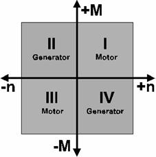
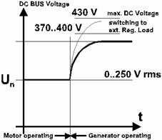
Fig. 51
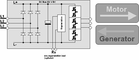
Fig. 52
Characteristic curve |
The servo motor can operate continuously with the nominal torque Mn up to the nominal speed nn.
The servo motor can deliver the peak torque MS during intermittent (pulse) operation. Since torque is determined by current, the exact duty cycle and maximum on-time is determined by the thermal characteristics of the motor, and the maximum tolerable flux-density of the permanent magnets. A motor can be permanently damaged by partial de-magnetization, which is caused by applying excessive current, even for a short time. Currents below the de-magnetization threshold can still cause overheating which can damage the winding insulation, especially if the motor is operated in a hot environment. Severe overheating can also cause de-magnetization.

Fig. 53
Operating cycles of servo motor |
In most applications, servo motors are
called upon to deliver peak torques during the acceleration phase. This follows directly from
To avoid overheating of motor and amplifier the effective current within a duty cycle has to be equal or less than the nominal current.
![]()

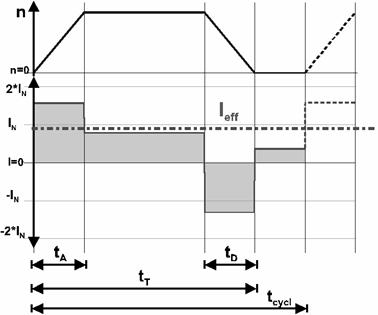
Fig. 54
Stepper motors |
Stepper motors are among the first Intelligent Motion devices developed. While the shaft is capable of continuous rotation in either direction, a stepper motor can only rotate one discrete step at a time, whenever a pulse of current is sent to the motor windings. The number of steps per revolution, and hence the degree of rotation per step, is defined by the natural step resolution which is in turn determined by the specific construction of the motor. The step-by-step motion allows positioning merely by counting the number of current pulses sent to the motor, provided that the motor does not stall. Because there is nothing to measure the actual motor position, stepper motors are controlled in an "open-Loop" fashion.
Common step resolutions for 2-phase stepper motors are 200 and 400 steps, and for 5-phase stepper motors 500 and 1000 steps. Special amplifiers called "micro-stepping" drives can electronically create virtual steps between the natural steps, although with reduced accuracy. Micro-stepping drives can achieve apparent resolutions of up to 10,000 steps per revolution.
Stepper motors can be divided into three basic types:
Reluctance stepper motor
Permanent magnet stepper motor
Hybrid stepper motor
Design principles, functional details and characteristics are described on following pages.
Reluctance stepper motor |
The reluctance stepper motor was the first stepper motor manufactured. Although its performance is poor, and this technology is obsolete, understanding its principle of operation is helpful when studying hybrid stepper motors, which are based on the earlier reluctance design.
The reluctance stepper motor (as shown below) consists of three stator coils and a soft-iron rotor. If a current is applied to a one of the stator coils, a magnetic flux flows in the stator core, which is concentrated in the gap between the rotor and stator teeth. The rotor will position itself to minimize the size of the gap. That is the reason this stepper motor is also call variable reluctance (VR) stepper motor.
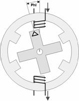
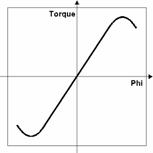
Fig. 55 - Reluctance stepper motor
The function principle of the VR motor is shown with the pictures below. The three stator coils (two poles per coil) are energized in succession, which causes the rotor teeth to align with the next pair of pole pieces. Note: Only the energized stator poles are shown in each picture.
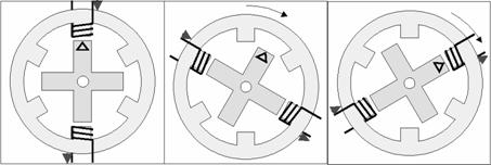
Fig. 66 - Variable reluctance stepper motor
Permanent magnet stepper motor |
The permanent magnet (PM) stepper motor is similar to the VR motor, except that the soft-iron rotor has been replaced by a radially-polarized permanent magnet. In this example, there are only two stator coils. The magnetic circuit is completed by the iron stator core. As in the VR motor, the rotor will align itself in such a way as to reduce the gap between the rotor poles and stator teeth.

Fig. 67 - Permanent magnet stepper motor
The operating principle of the PM motor is shown below. Switching the stator coils in succession will generate rotation of the rotor. The diagram shows the switching sequence for full step mode. Only the energized coil is shown. If only one phase is switched at a time it is called "wave drive". Switching both phases is called "normal mode".
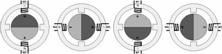
Fig. 68 - Operating principle of the permanent magnet stepper motor

Fig. 69 - Operating principle of the permanent magnet stepper motor
The combination of wave drive and normal drive gives the half step mode. The function principle of the half step mode is shown with the diagrams below.
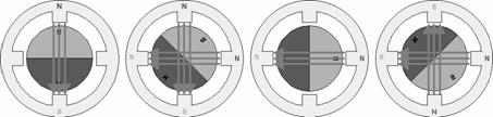
Fig. 70
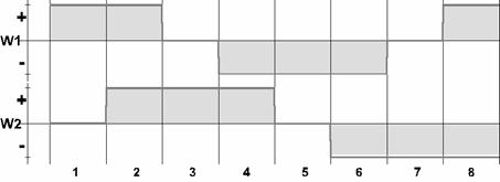
Fig. 71
As above the diagram shows, the stator coils must be energized in a 4-step sequence (full-step) or an 8-step sequence (half-step) in order to make a complete revolution. A motor with such a small number of poles is not a practical reality. This example was given only as a demonstration.
Although the resolution of a PM stepper motor can be increased by adding more poles, current construction methods limit the maximum practical number of rotor poles to 10, or so. This gives PM stepper motors with stepping angles down to about 7.5°.
Hybrid stepper motor |
The hybrid stepper motor is a combination of the VR motor and the PM motor. The rotor of the hybrid stepper motor is a toothed cylinder of soft-iron pole pieces. Between each opposing pair of pole-pieces is a permanent magnet. The two pole shoes are with an offset of half the width of a tooth. The soft-iron stator core also is toothed, and is wound with two coils, W1 and W2, shown below.

Fig. 72 - The operating principle of the hybrid stepper motor
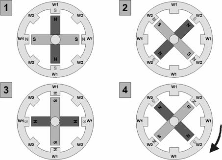
Fig. 73 - The operating principle of the hybrid stepper motor
3-phase stepper motor |
Although the most common stepper motors have two-phase stators, three-phase machines are made also. Even more phases are possible!
A special version is the 3-phase stepper motor. The functional principle is similar to the principles described before. The 3-phase stepper motor is a very new development. The advantage of the 3-phase stepper motor is a simpler control amplifier.
Fig. 74
Micro step mode |
The number of steps (e.g. the natural stepping angle) of stepper motors is limited by manufacturing and economic constraints. The best available resolutions are on the order of 1000 steps/rev (0.36°) for 5-phase stepper motors, and 400 steps/rev (0.9°) for 2-phase stepper motors, when operated in half step mode.
Special applications requiring higher resolution may benefit from micro-stepping mode. This is an electronic method of increasing the apparent resolution by creating intermediate steps. This is accomplished my modulating the magnitude of the phase currents instead of simply switching them on and off, as shown in the diagrams below. Micro-step control can achieve resolutions up to 10,000 steps/rev.
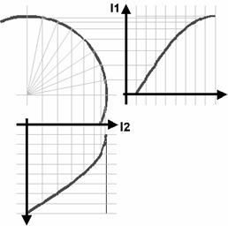
Fig. 75
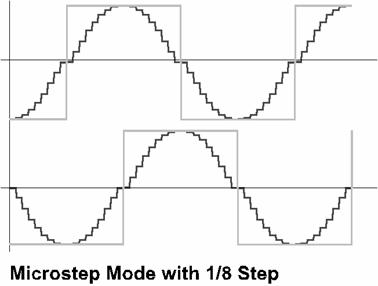
Fig. 76
5-phase stepper motor |
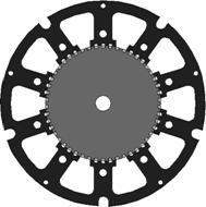
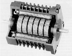
Fig. 77 - The construction principle of a 5-phase stepper motor (SIG Positec)
The resolution is calculated with the formula:
z = k * p * m k = 2 for full step, k = 4 for half step
p = number of pole pairs (p = 50)
m = number of coils (m = 5)
This gives 500/1000 steps at full/half step or stepping angles of 0.72°/0.36°.
5 lines wiring of 5-phase stepper motor |
Conventional 5-phase stepper motors require 10 wires to connect the motor to the stepper drive (amplifier). This results in a more complicated installation effort, and more complex electronics than 2-phase stepper motors. A good compromise is to use a "ring" or "pentagon" connection for the 5-phase coils, which reduces the required wires and switching transistors by one-half.
The switching diagram for the 5-phase stepper motor is shown below.
Fig. 78
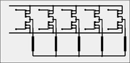
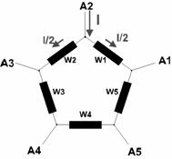
Fig. 79
Characteristic curves |
The performance of a given stepper motor/amplifier package can be is characterized with a "torque-speed" diagram.
For all stepper motors, the operating torque decreases with higher stepping frequencies. Furthermore, the operating range is divided into a "start" region and an "acceleration" region. Within the start region, the motor can track any frequency change instantaneously without losing steps (stalling). This is a limitation of the step torque, which is determined by the maximum phase current, and the inertia of the rotor.
Above the start frequency only continuous frequency changes (Acceleration ramps) are allowed. The start region is shown by the start frequency curve, below.
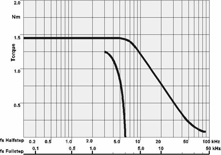
Fig. 80 - Torque vs frequency curve.
The start frequency curve in the diagram above is valid only for no external load. The start frequency with external load has to be decreased.
To find the actual start frequency a detailed diagram is needed as shown below. The actual moment of inertia in the lower diagram gives a line up to the upper diagram. The start frequency curve of the upper diagram now has to be shifted to the right (to lower frequencies) until it meets the line from the lower diagram. The intersection with the actual torque gives the actual start frequency.
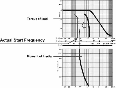
Fig. 81 - Torque vs frequency curve.
While this appears complicated, it is really quite easy to understand if you remember F=ma. When a stepper motor begins turning from a complete stop, the generated torque accelerates the rotational inertia of the rotor and the attached load. Higher rates of acceleration require more torque. Because the available torque is limited, only moderate rates of acceleration are possible. Therefore, the initial applied frequency must be low enough so that the motor does not attempt too rapid an acceleration. The frequency must be started at a low value and then gradually ramped up, or the motor will stall, and the position reference will be lost. The complex acceleration profiles required to prevent stalling are best provided by a dedicated stepper motor Indexing control. Most ordinary PLC's, for example, are poorly suited for this task.
Frequency ramp |
If the stepper motor is operated below the start frequency (that means with low speed), the motor can start and stop directly with the operating frequency.
To use the full range of speed of a stepper motor, the operating frequency has to be change by a ramp between start frequency and maximum frequency. It is the same with stopping the motor.
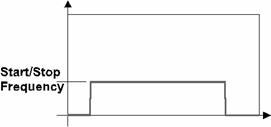
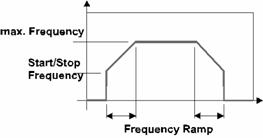
Fig. 82 - Frequency vs time curve.
Stepper motor drive (amplifier) |
The stepper motor drive is often called an amplifier, but it is really more complex than that, as shown below. The control signals (pulse, direction etc.) are connected via the control signal interface (normally optically isolated). The control logic generates the sequential control signals for the power stage depending on full/half step mode. The coils of the motor are driven by the power stage.
The basic control signal input format for stepper motors is called "step and direction." The "step" input accepts a variable frequency input that determines the instantaneous motor speed, and the "direction" input determines direction (1=CW and 0=CCW). These signals are generated by all common stepper-motor indexing controllers.
The phase coils are usually switched on via a constant current source. This gives better performance by mitigating the effects of the inductive reactance of the windings, which increases with the frequency. Without constant-current regulation, the winding current would decrease as the frequency increases, limiting the available high-speed torque.
At least one coil is always energized, even when the motor is stopped. For this reason, most stepper motor drives also have a current select input, which is used to select between "run" (high-current) and "park" (low current). This allows the motor to run cooler and save energy, and is appropriate for applications that do not require high holding torques.
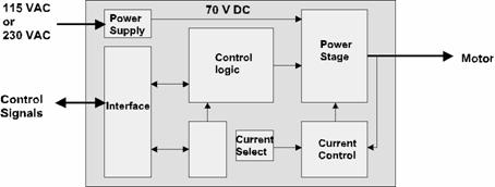
Fig. 83
Controlling a stepper motor |
A stepper motor amplifier is controlled by pulse and direction signals via a position control. There is no feedback, meaning that it is an open-loop control.
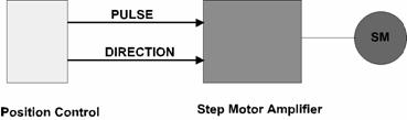
Fig. 84
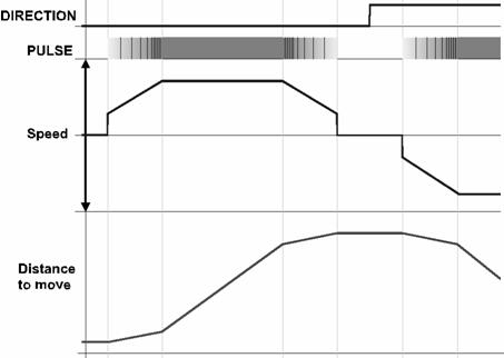
Fig. 85
Stepper motor with rotation monitoring |
Since most stepper motor applications run in an open-loop fashion, there is no way to verify that every step input resulted in a corresponding increment of travel. This is, nonetheless, the most common mode of operation, because the main advantage of using a stepper motor is the simplicity and reduced cost that results from not needing feedback.
Some special applications need a higher safety level. Therefore it is possible to operate the stepper motor with rotation monitoring. The rotation monitoring is done with an position encoder integrated into the stepper motor. A monitor circuit compares the control signals (pulse, direction and full/half step) with the feedback signals from the incremental encoder and signals if a step error occurs. While this was a common solution in the past, there is now little advantage to using this scheme. With today's available technology, a closed-loop servo system can be substituted for a marginal increase in cost, resulting in dramatically improved performance compared to any stepper motor system.
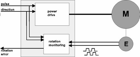
Fig. 86
Intentionally blank
|
