FACULTY OF MATHEMATICS AND COMPUTER SCIENCE
COMPUTER SCIENCE SPECIALIZATION
BACHELOR'S DEGREE IN COMPUTER SCIENCE THESIS
MDA: The Model Driven Architecture

CLUJ NAPOCA
2005
Figure 1 MDA in OptimalJ - structure coined by Compuware in 2003
Figure 2 The PATRIR Gandhi Peace Library Use Case Diagram
Figure 3 Multitiered applications [21]
Figure 4 The J2EE server and containers [21]
Figure 5 The PATRIR Gandhi Peace Library Domain Model
Figure 6 The PATRIR Peace Library Relational Data Schema
Figure 7 EJB simplified metamodel [17]
Figure 8 Simplified Web metamodel [17]
Figure 9 Transformation pattern for Business tier in Code model [19]
Figure 10 Transformation pattern for Presentation tier in Code model [19]
Figure 11 Structure of x152.x111.library.application.common package
Figure 12 Structure of x152.x111.library.application.common.resource package
Figure 13 Structure of x152.x111.library.application.businessfacade package
Figure 14 Structure of x152.x111.library.application.businesslogic package
Figure 15 The PATRIR Gandhi Peace Library main page
Table 1 Transformation pattern from UML model to Domain Class model [19]
Table 2 Transformation pattern for Domain Class model to DBMS model [19]
Table 3 Transformation pattern for Domain Class model to BusinessLogic model [19]
Table 4 Transformation pattern for BusinessLogic model to Business Façade model [19]
Table 5 Transformation pattern for Domain Class model to Application Common model [19]
Table 6 Transformation pattern for Domain Class model to Web model [19]
Table 7 Transformation pattern for the Domain Class model to Web Data Types model [19]
Table 8 Statistics: Java classes, code lines without comments and blank lines in the Common package
Table 9 Statistics: Java classes, code lines without comments and blank lines in the BusinessFacade package
Table 10 Statistics: Java classes, code lines without comments and blank lines in the BusinessLogic package
Table 11 Statistics: Files in web module, number of lines in jsp files
contents
Introduction
Statement of Purpose
Thesis Support and Example Implementation
Chapter 1. MDA Overview
The Object Management Group (OMG)
1.2. The Model Driven Architecture
1.3. MDA Benefits
Chapter 2. The MDA Framework
2.1. System
2.2. Model
2.3. Platform
2.4. Viewpoint
2.5. Model Transformation
2.6. Model elaboration
2.7. Languages
Chapter 3. Building Models
3.1. The Rationale of Models
3.2. Abstraction, Classification, Generalization
3.3. Model Projections
3.4. Models and Platforms
3.5. UML as PIM Language
Chapter 4: Building Metamodels
4.1. The Rationale of Metamodels
4.2. The UML Example
4.3. The MOF
4.4. The XMI
4.5. The CWM
Chapter 5: Building Mappings, Marking Models. Enabling Transformations
5.1. Mappings
5.2. Marking Models
5.3. More on Transformation
Chapter 6: Elaborating Models
6.1. The Idea
Chapter 7. MDA Today
7.1. MDA Technology Base
7.2. Tools
7.3. Development Processes
Chapter 8. The PATRIR Gandhi Peace Library Application
8.1. The Problem
8.2. Requirements
8.3. J2EE Overview
8.4. The PATRIR Gandhi Peace Library Domain Model (PIM)
8.5. The PATRIR Gandhi Peace Library Application Model (PSM)
8.6. The PATRIR Gandhi Peace Library Code Model
8.7. How to Use the PATRIR Gandhi Peace Library
8.8. Conclusions
Chapter 9. The Future of MDA
9.1. The Job of the OMG and Standards Developers
9.2. The Job of the Tool Vendors
9.3. The Job of the Developers
Bibliography
"In the beginning, there were programmers. They wrote software and, mostly, people found it was good. Then the platform changed, so they wrote it again. And again and again. Software was rewritten through changes of operating systems, databases and architectures. Sometimes there were even improvements on the time before but often it was little more than a port." (Quocirca - www.silicon.com - Is Programming Dead?)
MDA, Model driven Architecture, the "flagship specification" of the OMG, Object Management Group, is a small step in turning the craft of software programming into an engineering discipline.
MDA - Model Driven Architecture by OMG thesis is a research thesis conducted 20520e42u with the final goal of acquiring better understanding of a trend that will prove revolutionary in the software development process. Like the passage from assembler to 3G languages (C++, Smalltalk, Java), MDA technology promises a shift in the common developer's approach to software engineering. The agreement is still to be proven - through its adoption and acceptance by the businesses that decide to use it. It would appear, however, that it is only a matter of time.
The PATRIR Gandhi Peace Library example from Chapter 8 can be executed using the OptimalJ tool.
"This can never work. You cannot generate a complete working program from a model. You will always need to adjust the code", sceptics abound. The Model Driven Architecture is at its beginnings and still it promises a radical change in the ways software systems are built. Good tools have effects in productivity, overall costs, interoperability, portability, testing and maintenance. Discussion on these topics and more follow.
In the modern age, humanity has seen the highest rate of progress and development ever in its entire existence. Industrialization, urbanization, and all their effects on the life-style of many and the environment. The advent of computers, telecommunications and information systems, the concept of information and the increasing role of those with access to it. The ever changing economic environment requests increasing the IT infrastructure within organizations to ease flows of information. The infrastructure connects people all over the world in a growing need to exchange political, economic, social, and cultural data. The link between the clients and suppliers of these has increased. Today,the global network, the Internet, is a large, rapidly growing net of distributed operating systems, catering to the needs of all. To allow this there is the necessity of standards.
The Object Management Group (OMG) was formed in 1989. It is an international not-for-profit software consortium, a vendor-neutral membership-driven organization.
Among some of
its distinguising members are IBM, Sun Microsystems, Alcatel,
Its objective is to support the process of developing standards in the field of distributed object computing. This process has an open and vendor-neutral status and is maintained by proposing technologies, inviting proposals and inviting feedback from the member companies before coming into agreement on a final specification, this becoming an adopted standard.
Over the years, it has been active in horizontal markets promoting CORBA(Common Object Request Broker Architecture), IIOP(Internet Inter-Orb Protocol), UML (Unified Modelling Language), and MDA(Model Driven Architecture). The vertical markets influenced by these standards are healthcare, finance, telecommunication, and others.
Our world of IT is marked by change, in computing infrastructures, implementation platforms, interconnection standards as computers and networks become faster and cheaper. There is the need of the new technologies and applications to interoperate with legacy systems.
Multi-platform MDA is based on the modeling specifications of the MOF(MetaObject Facility), a common basis for meta-models, the UML(Unified Modeling Language), a "general - purpose visual modeling tool to specify, visualize, construct, and document the artifacts of a software system"(from UML Reference Manual), XMI(XML Metadata Interchange), a standard for metadata information exchange via XML, and CWM(Common Warehouse Metamodel), a specification describing metadata interchange among data warehousing, business domain, information management and portal technologies. OMG's own middleware platform is CORBA, which includes the Interface Definition Language OMG IDL, and protocol IIOP.
MDA is an approach to using models in software development in such a way that the software development process is driven by the activity of modeling of the sytem. Models are transformed from expenses to assets.
But the question arises: "Are models important for enterprises?" Dan Haywood, in his article,MDA: Nice Idea, Shame About The., argues that if the organization values LDMs (logical data models) they will value PIMs since LDMs are the backbone of PIMs.
Another issues: "Is the activity of the company stable?" OMG gives an MDA-based system a life-span of about 20 years, if the basic operation of an organization is not stable then probably the investment will not be profitable, or if the business change is in pace with the technological development then a platform independent approach is not needed
Finally, "Would your business buy it?" Getting the organization to understand MDA is typically a hard sell. Is the business ready to invest early in debugging and development of transformation?
What will the consequences of this shift in the developers realm be? Probably request for Java,C#,VB developers will drop in favour of model analysts and transformations developers, this implies change in training costs for the businesses.
MDA is a complex, yet powerful approach to developing extensible and maintainable systems. It caters to an ongoing business and technology change. The MDA separates the business and application logic from the specifics of the underlying platform.
In the process of separation of concerns, MDA provides an approach for, and enables tools to be provided for specifying a system independently of the platform that supports it, specifying platforms, choosing a particular platform for the system, and transforming the system specification into one for a particular platform.
Some possible applications are in the fields of healthcare, transportation, e-commerce, space technology, manufacturing, telecommunications, finance and more. The domain widens though as tools get better, as expertize increases, and world-wide research focuses on the field.
The adoption of MDA on the market has caught on faster than any other OMG standard making John Siegel, the Object Management's Group vicepresident of technology transfer, state that he is "extremely enthusiastic". Organizations such as Deutsche Bank Bauspar, Austrian Railways, ABB, CGI, Wells Fargo, Unisys, AIM Investments, Danzas, the Swedish Parliament and others have developed projects using the technology.
A tabular expression of the process is presented below.
|
Building an Application Using MDA An MDA-compliant tool applies standard mapping to generate a platform-specific model, for middleware based on J2EE or XML/SOAP, from PIM. MDA tool generates all or most of implementation code for deployment technology. | |
The Middleware Company, a "knowledge network for middleware professionals," is out with the results of its productivity research on developers maintaining or enhancing a J2EE application using Model-Driven Architecture (MDA) and code-centric approaches. The research found that MDA increases maintenance productivity by 37 percent over a traditional, code-centric approach, The Middleware Company reports. An earlier study conducted in 2003 showed that MDA increases the productivity of creating new J2EE applications by 35 percent. According to The Middleware Company, "The study, which measured the effect of a model-driven, pattern-based development approach on J2EE application maintainability, consisted of two highly skilled development teams that performed a set of typical but diverse enhancements to an existing application. One team used an MDA-based tool, Compuware's OptimalJ, while the other used a traditional enterprise-caliber integrated development environment. MDA proved particularly well suited for enterprise-class applications as it was found that productivity benefits increased with the complexity of applications and data structures. MDA was also very successful in handling integration technologies such as JMS, Web services and J2CA." "The team using an MDA approach completed five enhancements in 165 hours versus the 260 hours it took with a traditional one," said Will Edwards, vice president of research and practice management at The Middleware Company. "Our results show MDA's ability to reduce coding time and simplify design decisions. The Middleware Company clearly finds Model-Driven Architecture to be a significant and important technology for improving application time to market."
Higher productivity for architects, designers, developers and administrators is supported also by reduced costs throughout the application life-cycle, reduced development time for new applications, improved application quality, increase in the return on technology investments, and also a rapid inclusion of new technological benefits into existing systems.
In the search for reusability we find web services, the generic term for a set of standards for how application software elements talk to each other. Web services wouldn't exist without all the work that's gone into the development of application architectures that take most of the work out of the software plumbing - Enterprise Java (J2EE) and Microsoft's .Net architecture. One gave rise to the other, catalysed by other standardisation efforts such as the adoption of XML and the acceptance of programming, design and analysis patterns that dictate common structures and where they should best be used. The second reason, which is also linked into the application architecture work, is the unification of standards for describing what applications look like. The whole world has settled on a single modelling language to describe the innards of applications, known as the Unified Modelling Language (UML). The standard is now at 2.0, which means that it covers the vast majority of requirements. It's not perfect but it is certainly comprehensive. Application reuse faces the problem of architectural mismatch, word coined by David Garlan, signifying the situation in which systems and/or components have a different idea about how they fit together inside the system. The MDA-based additive solution imposes the software architecture only at the last minute in the form of bridges between layers that take one interface and link it with the neighbouring one, a system of mappings available only at deployment time -thus ensuring that models are assets, not expenses, hence enabling design-time interoperability.
The MDA architecture assures portability, cross - platform interoperability, platform independence, domain specificity, productivity, long-term flexibility of implementation - integration of new implementation infrastructures - , integration - establish automatically the connection between the design and the new integration infrastructure - , maintenance - simpler because of the direct access to the system specification available in a machine-readable form - , testing and simulation - models can be validated against requirements, and various infrastructures, can be used to simulate the dynamic behavior of the system in design.
This chapter introduces the MDA framework that lies behind the process that we described in Chapter 1. The MDA framework consists of a number of elements that fit together in a specific way.
We present MDA concepts with respect to some existing or planned system.
The Wikipedia Encyclopedia gives us the following definition of a system: "A system is an assemblage of inter-related elements comprising a unified whole. From the Latin and greek, the term system meant to combine, to set up, to place together. A sub-system is a system which is part of another system. A system typically consists of components (or elements) which are connected together in order to facilitate the flow of information, matter or energy. The term is often used to describe a set of entities which interact, and for which a mathematical model can be constructed". In computer science and information science, system could also be a method or an algorithm. System can also be used reffering to a framework, be it software or hardware, designed to allow software to run.
It is a program, a single computer system, some combination of parts of different systems, a federation of systems, each under separate control, people, an enterprise, a federation of enterprises.
The organizational structure of a system is an architecture: it's composing parts, the connections between them, how they interact with each other, and the guiding principals which define the design of the system.
A model of a system is a description or specification of that system and its environment for some certain purpose. It is a semantically complete abstraction of a system.
The representation of a model is most often graphical and textual. The graphical representation is realized via a CASE tool based on a visual modeling language, like UML, while the textual representation is either in natural language or in a programming language. The necessity of having both representations lies in the need to have a more accurate depiction of a system and it's functionality, analysis and design.
The term model-driven in MDA signifies that the architecture provides a means for using models to direct the course of understanding, design, construction, deployment, operation, testing, maintenance and modification.
Today separate teams are working on the same project, resulting in 3 platform-specific versions of one system. This kind of process has triple costs than in the MDA vision where we bring together the model of the system and make the appropriate subset, describe the way it is to be linked with the model of the platform, map them one onto the other, and finally generate the system. The main result, rendering models as assets.
Efficient modeling also implies some degree of abstraction, classification and generalization strategies. More on these in Chapter 3: Building Models.
A model that defines the language for expressing a model is a metamodel. An instance of a meta-metamodel. It defines the structure, semantics, and constraints for a family of models. Examples: UML based on MOF, the rules for model interchange expressed via XML Metadata Interchange, Java specification, Common Warehouse Metamodel (CWM). Chapter 4: Building Metamodels covers the topic in greater depth.
What counts as a platform is relative to the purpose of the modeler. For many MDA users, middleware is a platform, for a middleware developer an operating system is the platform.
Platform describes some sort of framework, either in hardware or software, which allows software to run. Typical platforms include a computer's architecture, operating system, or programming languages and their runtime libraries. Some specific real-time platforms are Java, CORBA, .Net ; Linux, Mac, Windows.
It has to have an implementation, also known as realization. There are two types of realizations: primitive realization - a stand-alone specification of a platform, and composed realization - which means as the name implies a realization comprising more realizations.
The concept of platform independence implies the software can be run on any computer. When talking about a model that it is platform independent, it means the model is independent of the features of a platform of any particular type
A platform model is a specification of a particular architectural style
Services available in a wide range of platforms are pervasive services.
A viewpoint on a system is a technique for filtering certain architectural concepts and structuring rules in order to focus on specific concerns within that system.A model instance of the viewpoint is a view. An MDA based system has 3 viewpoints: computation independent viewpoint, platform independent viewpoint, platform specific viewpoint.
The computational independent viewpoint focuses on the environment of the system, and it's requirements. The Computation Independent Model (CIM), or domain model, is a view of the system from the computational independent viewpoint. In it the details of the structure of the system are not revealed and the vocabulary of the business domain is used. The domain experts and the design and implementation of artifacts experts are brought together to agree on the domain requirements and functionality of the system.
The platform independent viewpoint focuses on the operation of the system while hiding the details necessary for a particular platform. The Platform Independent Model (PIM) is a view of the system from the platform independent viewpoint. It has a particular degree of platform independence such that it can be used with a number of different platforms of similar type. Such models are unaffected by the underlying platform, are technology independent. The model comprises only of business functionality and behavior, and changes only when the business conditions require it.
The platform specific viewpoint is a combination of the platform independent viewpoint with an additional focus on the detail of the use of a specific platform by the system. The Platform Specific Model (PSM) is a view system from the platform specific viewpoint. Constranting with the PIM, the PSM is technology dependent, the business functionality and behavior are expressed in a formal manner, while run-time characteristics are also specified.
MDA promotes automation at a higher level of abstraction. Models are in machine readable formats and the process of converting one model to another model of the same system is called model transformation. It produces from a PIM a model to a particular platform, such as the output of a database schema from a UML model, the source language being UML and the target language SQL. Since code is another model, code generation is another type of model transformation.
MDA does not clearly specify how the transformation from a PIM to a PSM is to be done, but there are several approaches of achieving this, tool specific since this is an automated process.
Because MDA must support iterative and incremental development the practice of mapping between models happens at different abstraction levels and is a repeatable action. A mapping function is defined which follows specific mapping rules to transform the source model(s) to a target model. To aid in the process of automation come marks, which are lightweight model elements applied to source model elements without polluting them, particular for every mapping. They are an extension mechanism defined by a marking model, which describes the structure and semantics of a type of marks. The context in which marks are applied are additional inputs or additional outputs. These issues are discussed in Chapter 5 .
The action of modifying a model to fit new requirements is model elaboration. It is analogous to constructing a design model out of the analysis model.
Such that the MDA approach be fully exploited there are some principles to model elaboration.
No model elaboration unless necessary.
No "intermediate" model elaboration if it is not meant to be exposed.
"Localize elaborations and avoid redundancy in elaborating locations.
In the case of a repeated transformation arises the issue of maintaining the modifications to the model. An approach is to have protected areas, an area in the source model that is preserved upon applying a mapping function. Factors like detecting manual changes in target models, preserving/merging manual changes during mapping, avoiding the loss of manually-created information need to be taken into consideration.
To ease into the new way of developing software, one can use the reverse engineering practice to transform already existing code into the model representing it. Such that the models are well-defined, they must be synchronized in both directions from code model to application model and vice-versa.
Chapter 6 elaborates on these.
Formal definitions (abstract syntax) of new languages in the context of MDA have two purposes:
Ways to achieve this include:
The ultimate abstraction of a system is the model, the set of diagrams, describing it. It is the main building block of the MDA approach, the point where it starts. Below we discuss in more depth the role of models in making MDA viable.
"In the past you'd have this nice picture to help communicate with other people. Then the 'real' work of coding had to be done. MDA makes modeling concrete - UML is becoming a programming language again, something that really executes." (Wim Bast, Amsterdam-based chief architect of Compuware OptimalJ)
The most difficult part of obtaining an end product from a set of requirements remains getting the right abstraction that complies. Models exist in all areas: the blueprints for civil engineers, the drawings of an architect, the storyboarding in advertising and movie industry, the reports of an accountant.
Applications developed along with the expansion of the new state of the world economics, growing business needs, emerging technologies. Before long a certain type of planning was necessary in order to cope with building larger, more complex software systems, and the fact that more and more people were involved in just one project, modeling.
To create some order and transparency in working with models five modeling maturity levels (MMLs) can be classified.
Level 0: No specification
It is the approach adopted mainly by non-proffesional software developers working on small applications that do not require a development process. Choices with respect to design are made ad-hoc and can create conflicting views between those involved. The real issues arise when the developing team is not the same with the maintainability crue, the readability level is low and maintaining such a system can prove to be quite difficult.
Level 1: Textual
At the lowest level of professional software development documents are written in one or more natural languages. Natural language is ambiguous, which can lead to different interpretations of design decision by different coders. In the event of a system change, updating the documents is very difficult due to the high coupling in the structure.
Level 2: Text with diagrams
At this level, the architecture of the system system is specified using textual representation supported by several visual modeling artifacts, such as high-level diagrams. While the issues detected in Level 1 still hold, readability and understanding of the system is aided.
Level 3: Models with text
A set of models, diagrams and text having specific semantics, form the basis. Text is also used to provide more information, define the environment, express conditions and such. The models with text are real representations of the system. Direct engineering is mostly manual, model to code. On the downside, difficulty to update the models is maintained, and the coder still makes business decisions, but their impact on the system architecture is less.
Level 4: Precise models
At the basis of software development is a coherent set of diagrams and text, forming the model, well-defined and specified. MDA is targeted at this level. Coders no longer make business decisions, updating models and code is easy, and code generation - direct engineering - is facilitated.
Level 5: Models only
This level is the ultimate goal in software development, unfortunately it has not yet been achieved. The model of the system is complete, consistent, precise, and detailed. Automation of the code generation produces a runnable system that requires no change. This phase is invisible to the coder since the transformation is reliable. Text is still present but only corresponding to comments.
For example, this is how UML is reflected in the MMLs.
MML 0: No use of UML
MML 1: No use of UML
MML 2: Moderate use of UML
MML 3: Extensive use of UML
MML 4: Extensive use of UML and OCL
MML 5: ???
Ultimately, what makes a good model is the capacity to serve as a means of communication by illustrating some ideas quickly and easily. The model is an accurate reflexion of some real, abstract, or hypothetical reality. Eventhough some parts of it are omitted, nonetheless their effects are considered in reasoning about the system. Model filtering simplifies the process of system analysis by aiding in determining solutions to the issue at hand, and help the overall understanding. The costs of building a model should be less than the building of the real thing.
Key concepts in modeling are abstraction - keeping what is relevant, classification - organization, grouping commonalities and generalization - general - particular relationship. A combination of these leads to the formalization of knowledge of some universe of discourse in a model.
Abstraction is the act of identifying the essential characteristics of a thing that distinguish it from all other kinds of things. It involves looking for similarities across sets of things by focusing on their essential common characteristics. For example, all triangles have three vertices, and have an area, and a perimeter, all houses have roofs, rooms, walls and doors. An abstraction always involves the perspective and purpose of the viewer; different purposes result in different abstractions for the same thing. To define a house, it is possible to express it as only having walls and doors. The levels at which a model is represented differ with respect to precision, concreteness, and optimization.
Classification and generalization are embedded in the abstraction process. They determine the level at which a model is expressed. In order to find the essential common characteristics we classify , group commonalities into a class, which then represents the thing. The relationship between elements at different levels of abstraction is described as a generalization. The more specific element is fully consistent with the more general one and contains additional information. An instance of the more specific element can be used where the more general element is allowed.
For a model to be useful, we not only need to be able to abstract away presently-not-relevant subject matters, and use a language at an appropriate level of abstraction, but we should also try not to show everything at once. Consequently, we need multiple complementary and interrelated projections that, when taken together, form a complete model. This brings us to yet another form of abstraction: simply leaving stuff out. Some models may be plain incomplete at a given level of language abstraction. MDA is perfectly happy with this situation in general (so long as the missing elements are added eventually, of course). A typical situation where this occurs is in the addition of handcrafted code. There's nothing wrong in having MDA support handcrafted code, as long as you don't take it as an "out" but instead use it with care. As a rule, you should express everything you can in the model.
The discussion so far has concerned itself with the various properties of a single model. However, MDA is all about transforming between models, each of which captures one or more subject matters and each of which is expressed in a language with a specific degree of abstraction.
The MDA standard defines the terms PIM and PSM. The OMG documentation describes this distinction as if this is a clear black-and-white issue. A model is always either a PIM or a PSM. In reality it is difficult to draw the line between platform independent and platform specific.
The only thing one can say about different models is that one model is more (or less) platform specific than another. Within an MDA transformation, we transform a more platform independent model to a model that is more platform specific. Thus, the terms PIM and PSM are relative terms.
They are connected to each other since they represent the system at different levels of abstraction.
The level of completeness, consistency, and unambiguity of a PIM must be very high. Otherwise, it is not possible to generate a PSM from a PIM. Let's investigate to what extent UML is a good language for building PIMs.
Plain UML
UML 2.0 is the new version for UML going through the standards process at OMG.
The structure of the UML is defined in four formal specifications: Infrastructure Specification.ptc/ 03-09-15, defines the foundational language constructs required by UML 2.0, Superstructure Specification.ptc/ 03-08-02, defines the user level constructs required by UML 2.0, OCL Specification.ptc/ 03-10-14, defines the Object Constraint Language (OCL), version 2.0., and Diagram Interchange Specification.ptc/ 03-09-01, enables a smooth and seamless exchange of documents compliant to the UML standard between different software tools.
Some highlights of the new version are full UML query language, complete OCL metamodel, which allows full integration with the UML metamodel, concrete syntax strictly separated from the abstract syntax allowing alternative syntaxes, and the semantics is defined mathematically and in UML.
The strongest point in UML is the modeling of the structural aspects of a system. This is mainly done through the use of class models, which enables us to generate a PSM with all structural features in place.
The weak area in UML is in the behavioral or dynamic part, which stops us from generating a complete PSM. UML includes many different diagrams to model dynamics, but their definition is not formal and complete enough.
Plain UML is suitable to build PIMs in which the structural aspects are important. When a PSM is generated, a lot of the work still remains to be done on the resulting model, to define the dynamic aspects of the system.
Executable UML
An executable model is a model that is complete in that it has everything required to produce the desired functionality of a single problem domain. Models run. This has become possible due to the UML action model.
Executable models for domains are not exactly the same as code (though they are something like aspect-oriented code) because they need to be woven together with other models to produce a system. These other models would include, of course, a meaningful user interface, a way of verifying who you are, and a way to store data properly.
Just as programming languages conferred independence from the hardware platform, executable models confer independence from the software platform, which makes executable models portable across multiple development environments. Software platform independence abstracts away glue code required to connect two components implemented using different technologies. Executable models therefore enable collaboration between different platforms, as well as projection to arbitrary platforms, which benefits projects supporting multiple iterations, releases, and configurations.
Executable models also provide for early verification. Because the model is executed, it can be shown to be correct (or not) as soon as it's conceived, without waiting for a design or an implementation.
Executable UML, a profile of the UML, makes this all possible with the help of Action Semantics (AS). It defines an execution semantics for a carefully selected, streamlined subset of the UML.
But there are a few problems:
Specifying complete behavior with state machines is only useful in specific domains, especially embedded software development. In other, more administrative, domains the use of state machines to define all behavior is too cumbersome to be used in practice.
The AS language is not a very high-level language. In fact, the concepts used are at the same abstraction level as a PSM. Therefore, using Executable UML has little advantage over writing the dynamics of the system in the PSM directly. You will have to write the same amount of code, at the same level of abstraction.
The AS language does not have a standardized concrete syntax or notation; therefore, you cannot write anything in a standard way.
UML - OCL Combination
When UML was under development OCL was used for added precision to the definitions of the elements of the modeling language. Also it was made accessible to modelers so they could express nuances that the graphical representation of models could not. It was a powerful addition to the object oriented analysis and design process.
It is an espressions modeling language, standard "add-on" to the UML. Strongly typed language - an OCL expression can be checked without the need for an executable, hence errors can be detected in an early stage. Declarative language - the focus is on the WHAT should be done, not on the HOW. No side-effects ensures this feature. In UML 1.1 OCL was used to specify constraints. In UML 2.0 it's uses exceed those of restrictions definitions. It can be used to write any expression on the model elements. The language can provide querying features, navigability inside models, actions specification and transformation specification. It has a mathematical basis on set theory and predicate logic, but the notation isn't formed of mathematical symbols. A balance between the mathematical rigor of definition and ease of use is especially valuable in MDA automated transformations.The learning curve is smooth and high making it suitable for widespread use.
In MDA all models need to be consistent, precisely defined and must contain as much information as possible. This is where OCL can be extremely useful. UML to visually represent the system, OCL for expression specifying. This tandem is needed to create complete models and therefore aid the simulation and testing phases, checking consistency, for generating PSMs using MDA transformations, and last but not least the code generation process.
Con opinions do exist though. Dan Haywood, who has worked on large and small software development projects for 15 years having worked previously at Accenture and Sybase UK and for the last 6 years as an independent consultant, trainer and technical writer, says in his article MDA: Nice Idea, Shame About the .: "While OCL is great for formally defining the semantics published interfaces between components, it's overkill to attempt to do this for the unpublished interfaces of objects within components. It just adds too much rigour at the wrong points in the development process, and in turn impedes agility".
Every language allows you to say something about the system, the higher level of abstraction of the language, the higher level in the specification. In the following, the role of the metamodel is presented.
Fundamentally, a metamodel is a model of the modelling language. Metamodels are useful to declare the elements of a modeling language such that mappings can be built between them. A metamodel is merely a model whose instances are types in another model. This allows us to capture the other model and manipulate it. A well-known metamodel is the specification for UML, which captures the classes in a developer's model. And another one is CWM. Moreover, metamodels may themselves be captured in metametamodels, the OMG standard form for which is the MOF. The MOF provides the means by which you will be able to tailor your metamodels and relate them to a standard MDA infrastructure. The existence of standards for representing models, metamodels, and metametamodels forms the backbone of the MDA infrastructure.
A primary application for metamodels is to enable the definition of transformations between models. To build such transformations, you have to understand the modeling language in which the source and the target models are expressed-which is to say, the source and target models as prescribed by the metamodels.
The instances of the class Class have values that are themselves classes from the original developer's model. This relationship is often informally called the instance-of relationship. It's important to recognize that this instance-of relationship-the one that is "meta"-is different from the instance-of relationship that relates instances at the same level of abstraction.
The UML metamodel is defined as one of the layers of a four-layer metamodeling architecture. This architecture is a proven infrastructure for defining the precise semantics required by complex models.
There are several other advantages associated with this approach:
The generally accepted framework for metamodeling is based on an architecture with
four layers:
The functions of these layers are summarized in the following.
META-METAMODEL
The infrastructure for a metamodeling architecture. Defines the language for specifying metamodels.
Example: MetaClass, MetaAttribute, MetaOperation
METAMODEL
An instance of a meta-metamodel. Defines the language for specifying a model.
Example: Class, Attribute, Operation, Component
MODEL
An instance of a metamodel. Defines a language to describe an information domain.
Example: StockShare, askPrice, sellLimitOrder, StockQuoteServer
USER OBJECTS (USER DATA)
An instance of a model. Defines a specific information domain.
Example: 654.56, sell_limit_order, <Stock_Quote_Svr_32123>
M3 is the metametadata that describes the properties that metadata can exhibit. This is the level at which modeling languages and metamodels operate. It provides a means to enable interchange between tools. M3 describes the modeling paradigm, it is a model of only the simplest set of concepts required to capture models and metamodels. M3 stands out as a constant in the modeling business because it is self-describing and there is no use for something above it in the abstraction sense, since that would be situated at the exact level M3. This is the reason why the standards groups put so much work in creating a standard at this level, which has given us the MOF.
MOF (Meta-Object Facility), a standard for metamodeling, its specification is available in the document Meta-Object Facility Specification which defines an abstract language and a framework for specifying, constructing, and managing technology neutral metamodels. It captures the structure and semantics of arbitrary metamodels-in particular, the UML metamodel-and also various kinds of metadata. UML and MOF are normally viewed in the context of a conceptual layered metadata architecture.
Further to this, the metamodels for MOF and UML are designed to be architecturally aligned, sharing a common subset of core object modeling constructs. This alignment allows the MOF to reuse the UML notation for visualizing metamodels. Actually the OMG are considering to merge these two standards. For the time being, the UML profile for MOF allows UML graphical notations for MOF modeling constructs.
The MOF also provides for standard data access, by defining supporting standards to be used by MOF-compliant languages to exchange and access complying models. One of these supporting standards is XMI, which defines rules for deriving an XML schema from a MOF-compliant modeling language as well as rules for rendering a compliant model into a compliant XML document.
The main purpose of XMI is to enable easy interchange of metadata between modeling tools (based on the OMG-UML) and metadata repositories (OMG-MOF based) in distributed heterogeneous environments.
"For the UMLers, XML is a way to interchange UML information, especially between different vendors tools. For XMLers faced with writing a very large and complex DTD, UML can be a methodology to design your information model. Then writing the DTD is a much simpler easy, whether you choose to automate the process (using the OMG's DTD design rules - known as XMI) or by hand." (Dr. Kerry Raymond)
The XMI Specification basically consists of: a set of XML Document Type Definition (DTD) production rules for transforming MOF based metamodels into XML DTDs; a set of XML Document production rules for encoding and decoding MOF based metadata; design principles for XMI based DTDs and XML Streams; concrete DTDs for UML and MOF.
XMI facilitates the communication and data interchange over the Internet among groups working in team development environments using tools and applications from multiple vendors. XMI also can be used to exchange information about data warehouses.
Data warehouses, abbreviated DW, are a collection of data designed to support management decision making. Data warehouses contain a wide variety of data that present a coherent picture of business conditions at a single point in time.
Development of a data warehouse includes development of systems to extract data from operating systems plus installation of a warehouse database system that provides managers flexible access to the data.
The term data warehousing generally refers to the combination of many different databases across an entire enterprise.
CWM is a metadata standard for data warehousing and business intelligence, which was adopted by the OMG in June, 2000 and which has gained wide support in the industry. CWM's strength is in its model driven architecture (MDA) that is based on and utilizes UML, MOF and XMI. It consists of a platform-independent metamodel definition, includes an XML-based inter-change format for metadata, also includes a mapping to a platform-independent API specification (CORBA IDL), and tools that standardize on CWM can readily share metadata via CWM-compliant XML files.
CWM is highly flexible and expressive. CWM does not, however, provide a means of expressing the intent, or intended semantics, of the content of an XMI file (this is beyond the scope of CWM). The answer to this is to define a CWM Metadata Interchange Pattern with the help of three elements:
Projection (or semantic context): Portions (subgraphs) of the CWM metamodel that are
semantically meaningful for some given interchange scenario.
Restriction: Boundaries on the number of instances of certain model element instances (or
constraints on their values).
Anchor: Starting element(s) for search of projected/restricted instances.
A CWM Metadata Interchange Pattern is an identified projection of the CWM metamodel,
optionally with restrictions on instances of that projection, and possibly with one or more specified anchor elements.
This chapter explains how transformations are defined. Not all users of MDA will define their own transformations; many will be incorporated in the MDA tools. Still, it is good to know how transformations are defined, especially because it enables you to make a more knowledgeable choice of tools.
MDA incorporates automatic transformations within early stages of the development process. The platform model determines the nature of the mapping.
To avoid the overcapacitation of the application model with design issues, the model-driven approach is to provide a separate mapping function that transforms the source model into the target model.
A mapping function is a collection of rules or algorithms that define how a mapping works. They are defined on metamodels, but they operate on models. Because the mapping applies to the metamodels it renders it reusable. It means having included repeatable design decisions. Their complexity can vary.
The model type mapping specifies a mapping from types in the source model to types in the target model. The metamodel mapping is a specific example of model type mapping. The types of model elements in the PIM and the PSM are also specified as MOF metamodels. Other type mappings may be defined. For example CORBA IDL language has means of defining types in the CORBA PSM
Two main features of the mapping function are construction and synchronization. The target model is constructed from the source model. Since they are derived, they are synchronized as well. To deliver these characteristics, mappings need to be executed automatically. The effects are a shortening in turnaround times, up-scaling to large models, and help to avoid manual work, the results are fewer errors and improvements on overall quality.
Automatization requires a formalism in which the rules can be expressed; the models must be formalized too. Recognition of these facts has led to QVT, for Query, Views, and Transformations.
There exist 3 approaches to formally specifying the rules of a mapping function: imperatively, archetype-based, and declaratively.
Specifying a mapping function imperatively means implementing all rules and algorithms in a procedural programming language that defines how to query data in one metamodel, transform it, and then write it out.
An archetype-based approach defines a mapping function as a set of templates that mix code or rules into the text to be generated. This can be implemented as a data access language that selects the appropriate elements from the source metamodel, selects which archetype to use for what source model elements, and then selects how to transform this information into something else that one can then insert into the target model.
A declarative approach to mapping specifies the algorithms as rules that specify what is to be produced, not how it's done.
Mappings can include marks. They can also include templates, which are parameterized models that specify particular kinds of transformations. Templates can be used in rules for transforming a pattern of model elements in a model type mapping into another pattern of model elements.
Other ways mappings can be used.
Refining mappings - vertical mapping (change the level of abstraction)
The mapping changes the level of abstraction. It can be a complete mapping, like Java compilers, which specifies completely the target model, or an incomplete mapping when there is necessary additional work to specify the target model, such as completing the target, or adding information in the source model without polluting it, or a combination of the two techniques.
Abstracting mappings - vertical mapping
The result of applying these mappings is they automatically abstract away information from the model. They are useful when moving models to different platforms, only the necessary information is ported.
Representing mappings
When a metamodel is not supported by readily available notations, and when each metamodel requires its own notation and tool support. In these cases, we can define a mapping to an existing metamodel for which notations and tool support exist.
Migrating mappings
These mappings reformat and regroup existing information to make it amenable to other mappings.
Merging mappings
If a mapping function weaves together aspects of multiple source models to combine them into a single target model, that mapping is called a merging mapping. Merging mappings create links between model elements from different models that don't make explicit reference to each other. An example is interoperability mappings. Mappings of two types of platforms are taken together. This mapping is then extended further to include connectors that bridge between the two platforms and specifications for the use of these connectors in a transformation. The purpose is to make compatible the parts of the system which belong to each platform and allow communication.
Refining mappings and abstracting mappings are called vertical mappings because they change the level of abstraction. Migrating mappings, like representing mappings,don't. To contrast these mappings from those that do change the level of abstraction, they are called horizontal mappings. Other examples of horizontal mappings are optimizations (typically to improve some computational quality like speed, small memory consumption, bandwidth, and so forth) and refactorings (typically to improve some "ility" such as maintainability, readability, and so forth).
Mappings can be reused after being processed. Some of the ways of doing that are: extension, combination and bridging. Extension acts on the initial mapping by making incremental modifications to create a derived mapping. The modifications consist of adding or altering the features of the base mapping. Mappings obtained this way form a mapping inheritance tree. Combination simply takes 2 or more mappings to create a new one. Examples are sequential combination and concurrent combination. The effects are the combined effects of the two mappings.
Models may be mapped by providing for particular ways of transforming to a certain platform. Thus, model instance mappings define marks.
Most mappings will consist of a combination of both, model type mappings and model instance mappings. This is so because model type mappings can express transformations only in terms of rules about the types in the PIM, which makes the mapping deterministic, leaving the whole job of the transformation on the PIM. A system of marks labeling types in the PIM helps to render the PSM the needed non-functional and stylistic characteristics.
Marks are platform specific. They may come from different sources: types from a model, roles from models, UML stereotypes, MOF elements, and/or elements specified by any metamodel. They may specify quality of service requirements on the implementation. Structure, constraints or extra modelling may be imposed on the mark system.
Transformations based on mapping functions are not enough. To complete the target model a system of marks is necessary. Marks are lightweight, non-intrusive extensions to models that capture information required for model transformation without polluting those models
Instead of defining marks within mappings, marking models cand be built. Such models are independent of mappings. This separation supports both model portability and longevity.The separation also provides the ability to evaluate a number of different mapping possibilities without requiring modification of the PIM. This is critical for efficient deployment of enterprise systems.
A marking model holds the same relation to marks as metamodels do to models. Hence, the instances of classes in a marking model are marks; stated in the other direction, marks populate marking models, just as a model populates a metamodel.
Mapping functions are the consumers and producers, the sources and the sinks, for marks, but what can a mapping function do with all of these marks? Rule selection is one way in which a mapping function uses marks. In cases where the mapping function has to fill in a blank in the target model, the mark acts as a value provider. Selector marks may also be quantities used to optimize the target implementation.
How do we connect the marks to the model elements to which they may pertain? A common practice is to view the marking model as a plastic sheet laid over the metamodel. The plastic sheet analogy suggests that some marks might be related and could all be placed on the same sheet. A single sheet could contain multiple related marks. A typical example of the usefulness of marking model grouping is a mapping function that spans multiple platforms. Marks may also apply to instances of classes of the developer models. Mapping functions can also produce marks for the target model as outputs, which can be useful if the mapping needs to remember how the source and target model elements map to each other. Another useful application of target marks is to allow one mapping to use the output of the other as its input. The target marks of the one are then used as the source marks of the other mapping function.
Since it is still early in the development of MDA, there is no specific way of implementing marks, when to use them, where and how much. But with time and experience there will also develop a better understanding and with it standards.
Effectively, the architect marks elements of the source model indicating which mappings to be used to transform it into a target model. Marking indicates that the element plays a role in the mapping.
A source model element may be marked once or several times. With the remark that in the latter case the marks belong to different mappings, and the model is transformed according to each of them resulting in target model elements accumulating features, or the target model receiving additional elements .
The transformation from the source model to the target model can be done manually, computer aided, or automatically. The input is the marked source model and the mapping, and the result is the target model and the record of transformation.
Direct transformation to code is possible. This occurs when a tool generates the code directly, the PSM may be made available read-only with the purpose of understanding and debugging.
Along with the target model a record of the transformation is produced. It represents a map from the elements of the source model to the precise element(s) of the outputted model, and also shows the parts of the mapping used in the process.
Here are some approaches to model transformation:
Marking.
A particular platform is chosen. A mapping for this platform is available or is prepared. This mapping includes a set of marks. The marks are used to mark elements of the model to guide the transformation of the model. The marked source model is further transformed, using the mapping, to produce the target model.
Metamodel transformation.
A model is prepared using a platform independent language specified by a metamodel. A particular platform is chosen. A specification of a transformation for this platform is available or is prepared. This transformation specification is in terms of a mapping between metamodels. The mapping guides the transformation of the PIM to produce the PSM.
Model transformation.
A model is prepared using platform independent types specified in a model. The types may be part of a software framework. The elements in the source model are subtypes of the platform independent types. A particular platform is chosen. A specification of a transformation for this platform is available or is prepared. This transformation specification is in terms of a mapping between the platform independent types and the platform dependent types. The elements in the target model are subtypes of the platform specific types.
Pattern application. Extension of the model and metamodel mapping approaches include patterns along with the types or the modeling language concepts.
Model merging. It is a generic approach in which the source model is merged with another model to get the target model.
Tool support in model transformation can vary in four directions:
Manual transformation.
Implies making design decisions during the development of a design conforming to requirements of the implementation. Since this is not much different than the way things have been done so far, MDA adds value by separating the source model from the target model and by making available the record of the transformation.
Transforming a source model prepared using a profile.
A source model may be prepared using a platform independent UML profile. This model may be transformed into a target model expressed using a second, platform specific UML profile. The transformation may involve marking the source model using marks provided with the platform specific profile.
Transformation using markings and patterns.
Patterns may be used in the specification of a mapping. The mapping includes a pattern and marks corresponding to some elements of that pattern. In model instance transformations the specified marks are then used to prepare a marked source model. The marked elements of the source model are transformed according to the pattern to produce the target model. Several patterns may be combined to produce a new pattern. New marks can then be specified for use with the new pattern. In model type transformations, rules will specify that all elements in the source model which match a particular pattern will be transformed into instances of another pattern in the target model. The marks will be used to bind values in the matched part of the source model to the appropriate slots in the generated model. In this usage the target patterns can be thought of as templates for generating the target model, and the use of marks as a way of binding the template parameters.
Automatic transformation.
There are contexts in which a source model can provide all the information needed for implementation, and there is no need to add marks or use data from additional profiles, in order to be able to generate code. A good example is that of mature component-based development, where middleware provides a full set of services, and where the necessary architectural decisions are made once for a number of projects, all building similar systems. These decisions are implemented in tools, development processes, templates, program libraries, and code generators. In this context, the developer need never see a PSM, nor is it necessary to add additional information to the source model, other than that already available to the transformation tool. The tool interprets the model directly or transforms the model directly to program code.
But any tool, in order to perform the transformation, needs to have the appropriate input. These can be: patterns, technical choices, quality requirements.
In this chapter we expand on the concept of model elaboration. Elaborating models implies that models are not complete and they need some tuning.
The idea is that a target model can be modified after it has been generated. Generally, this means adding code to the model, but it can also mean editing or refactoring the generated model. It is an advantage of the MDA framework because it allows developers to ease into model-driven development, rather than take a step function from a code-driven process to a model-driven development one. However, this should be taken advantage of with care such that the best of MDA can be exploited.
These issues should be considered:
Sometimes it is needed to see the model eventhough no elaborating is done, when the model is input for another mapping to understand better what is happening, when the target model is an artifact for the system so if they are made read-only they can be made available for documentation.
A situation to take under consideration is when the model is regenerated. The elaborated fragments need to persist. The concept of protected areas thus is quite useful. Everything inside this type of area is maintained during regeneration. In order that the source and target models not end up polluted by such, even if hidden, the developer should choose the granularity with reason.
But up to what point does the protected areas concept work? Suppose the signature of a method is generated, the implementation is given manually. What happens when the signature changes, when the method is deleted altogether? Approaches to solve this are diff-and-merge techniques. See the differences and merge. The problem is with merge conflicts, then the developer tracks the process by hand and decides which parts to keep or throw away. Another way is to tag manual changes while editing. Manually added elements don't have origin tags; on regeneration, elements with no origin are left alone. Finally, separating manual code and generated code by inheritance and callbacks is another way.
Reverse engineering and bidirectional synchronization of models comes then into discussion if we want to bring the manual changes to the higher level of abstraction. It is an easier task for people making the transition from code-oriented to model-oriented. An abstracting mapping is used to make it possible. It can also be used to move the model to a different platform. Problematic about frequently using abstracting mappings on the model is that the corresponding refining mappings produce 'fan-out' (from one source model to multiple target models as in the example of a three-tier application say presentation, application, and database). Therefore, to produce reversible mappings there are more rules necessary.
Legacy code is a model in itself. Approaches to incorporating it in the process towards MDA include generating code forward to a defined interface; the other is to "harvest" the legacy code and store it in a MOF repository. Of course, there must still be a mechanism to indicate references to the legacy, and that mechanism is marks.
We elaborate models if complete modeling is not possible or if it does not meet all of the nonfunctional requirements of a software development process. In addition, we may elaborate a generated model by reorganizing it.
How does MDA look so far? We see this in the following.
"So what's so great about MDA? If you think that there's nothing so new about it, I'll agree whole-heartedly. MDA is not a new invention; it is a bunch of techniques integrated under a single name. What's good news is that this leads to standards that are supported by different vendors, which is in general considered to be a good thing. MDA is thus an approach that is intended to solve problems common to application development in a standard way, freeing developers and architects from restrictions imposed on them by the complexity of today's technologies. " (Stefan Tilkov is CEO and Co-Founder of innoQ, a Germany-based consulting company focusing on software architecture for mission-critical systems. innoQ provides an MDA-compliant software generator, iQgen, that uses XMI for model input, JSPs as the template language and can generate any text-based software artefact.)
OMG has adopted a number of technologies, which together enable the model-driven approach. These include UML, MOF, specific models, and UML profiles. All specifications are available at the OMG site on the Internet.
Profiles are an extension mechanism A profile applies to a language specification, specifying a new modeling language by adding new kinds of language elements or restricting the language. That new language may then be used to build a model, or by applying the new or restricted elements to specific elements of an existing model. Any number of new profiles can be applied to an existing model, extending or restricting elements of that model. The modeler can later remove the application of a profile to a model; the result is that model as it was before application of that profile. Any model that uses a UML profile is a UML model. A model that uses a profile can be interchanged with a UML tool that does not support that profile; it will be considered by that tool as a model in UML, without the extensions of that profile.
More on some specific profiles.
MDA and Timeliness, Schedulability and Performance - the UML Profile for Schedulability, Performance, and Time Specification
"Real-time" categorized systems come in a very broad diversity: including soft real-time systems and hard real-time systems, timedriven systems and event-driven systems, distributed systems and centralized systems, fault-tolerant systems and non-fault-tolerant systems, and so on.
The issue with modeling real-time applications is that there is no formal specification of time and resources.
Nonetheless UML has all the necessary issues to address the needs of real-time systems, therefore no "heavyweight" extensions.Modeling techniques and concepts emerged each with it's own rules for representation, the UML profile for Schedulability, Performance, and Time Specification tries to find common framework that maintains the flexibility inside diversity, making room for specialization too.
The focus is on modeling time and time-related aspects - timeliness, performance, schedulability. Now rather than base your decision on perception, 'feeling', we should rely on mathematical results from accurate models.
Dealing with possible problems early in the development influences debugging load in the sense that it implies less rework, hence with less costs
As guiding principles, modelers should not feel compelled to use a specific modeling technique, rather to apply whatever method he/she feels works for the system under development. There must exist the posibility to construct UML models that help analyze and predict the most important properties of the real-time system. Modelers should be able to resort to different types of modeling techniques without having to understand the inner-most workings of them.Support should be offered for all existing techniques with extension possibilities. There should be possible to construct automatically various analysis-specific models directly from UML models
The approach and structure to building a performance, schedulability, timeliness profile is to leave it to the modeler to choose what works for the system under development since there is no recipe for success. Construct a framework to unify all concepts of real-time specific model analysis method, the basis of this framework being the "general resource model", these rules are taken, built a particular problem upon them and resulting in a "conceptual domain model".
MDA and model testing - UML 2 Testing Profile
The UML Testing Profile is based on the UML 2.0 specification. It defines a language for designing, visualizing, specifying, analyzing, constructing and documenting the artifacts of test systems. It is a test modelling language that can be used with all major object and component technologies and applied to testing systems in various application domains. The UML Testing Profile can be used stand alone for the handling of test artifacts or in an integrated manner with UML for a handling of system and test artifacts together.
The principles of design are:
Perfectly integrated within UML since it was built based on the UML metamodel
Reuse and minimality
It is organized in four logical groups of concepts:
Test architecture - concepts related to test structure and test configuration;
Test data - concepts for test data used in test procedures;
Test behaviour - concepts related to the dynamic aspects of test procedures;
Test time - concepts for a time quantified definition of test procedures.
MDA and modeling QoS (Quality of Service) and FT (Fault-Tolerance )
The profile defines a set of UML extensions to represent Quality of Service and Fault-Tolerance concepts. These extensions are integrated in two basic general frameworks QoS Modeling Framework and FT Modeling Framework.
The QoS Modeling Framework provides the general description of concepts used in high quality technologies.
The FT Modeling Framework includes notations to model risk assessments, with special care in describing concepts as hazard, risk, and risk treatment.
The characteristics of quality and their parameters are based on two types of concerns: i) user satisfaction, these parameters are based on the user or client requirements, and ii) resource consumption and system parameters, these are the parameters that support the resource managers of system infrastructures.
The developer of each component must consider its QoS requirements. Frequently the behavior of a system component is functionally correct, but the result it generates is nevertheless unacceptable because the result does not meet some QoS criteria, such as the response time and accuracy (i.e., quality).An approach is to use flexible components. A flexible component can trade off among the amounts of time and resources it uses to produce its results, the quality of its input, and the quality of its result.
Platform specifications and specialized platform technologies have been adopted by OMG. For instance, the basic CORBA technology, the CORBA language mappings, Realtime CORBA, Minimum CORBA, Fault-Tolerant CORBA, CORBA Components, and a diverse set of domain technologies.
MDA is not a novel concept. Database designers have been using a form of MDA for a long time. ErWin by Computer Associates is a CASE (Computer Aided Software Engineering) tool that provides MDA abilities to database designers and administrators. ErWin allows you to define your database design using a logical model. A logical database model is free from any database vendor specific details. In MDA terminology the logical model is a PIM. ErWin automates the process of converting the database agnostic logical model into a database specific (such as Oracle, SQL server, etc.) model. This database specific model is known as the physical model by database designers and as a PSM in MDA lingo. As I mentioned earlier, the process of converting a PIM into a PSM is called transformation. Finally, ErWin can be used to generate the SQL code (DDL) to create the database structure (tables, views, indexes, triggers, etc.) for the targeted database.
Based on the definition of MDA and the capabilities offered by the tool, ErWin is an MDA tool. In this case the modeling language is the well defined E/R diagramming notation
In my opinion, MDA tools, even with their existing limitations, have a definite place in any architect's toolbox. But then, everything can be taken to an extreme and the same applies to MDA, which is not without its associated hypes. Here are the two most common ones encountered:
MDA brings Software Architecture to the masses
MDA is a tool in an architect's toolbox. It is not the toolbox itself and it is definitely not the architect. MDA does not eliminate the need for competent and experienced architects, designers, and coders on the team. As the saying goes "Not everyone with a hammer in their hand is a carpenter".
MDA equals Software Architecture using pictures
Is this really possible? Even in database modeling, where a level of MDA is already being used, how far does MDA take database architecture? Talk with any database designer or DBA and you will quickly realize that most of their work does not really revolve around using a database modeling tool like ErWin. The same applies to software architecture in general. It involves much more than drawing pictures. In fact, one could argue that it involves too much, which is why people are still struggling to come up with a universally accepted definition of software architecture.
According to Dan Haywood, there are two types of MDA compliant tools today:
elaborationist - closer to the MDA specification. The basic elements are preserved: PIMs, PSMs. The PSM is annotated to generate 50%-80% worth of code, and the behavior is specified using a 3GL language : Compuware OptimalJ, iO-Software ArcStyler
translationist - the complete system is specified within the PIM, the code is 100% generated, behavior is specified using an action semantics language compliant with UML 2.0's Precise Action Semantics: Kennedy Carter, Bridgepoint
The MDA does not require a specific process to be used for software development. Processes are not standardized by the OMG, so you are free to choose your own. The are some of the processes of software development and how they are reflected in MDA.
Agile programming
A current trend in the software development process is to minimize the amount of effort and time spent in building models that will only serve as documentation, even though they do capture some of the interesting aspects of the software to be built. The purpose is to ensure that software is delivered that works for the users. Since requirements continuously change, the software that is being developed must change accordingly. The ability for a software project to accommodate changes in a flexible and immediate way is the core aspect of Agile Software Development.
Because changing a model means changing the software, the MDA approach helps support agile software development.
Extreme Programming
The XP approach is a very popular way of working, where the focus lies on writing code in small increments, such that you have a working system all the time. Each new requirement must be accompanied by an explicit test case, which is used to test the software. When adding new functionality, all previous tests are run in addition to the new tests, to ensure that existing functionality is not broken.
When we realize that the markers of a code model may take the form of MDA models that directly transform into code, creating these markers is not overhead anymore. On the contrary, the high-level models help to develop the software faster.
Rational Unified Process(RUP)
The RUP is a process that is much more elaborate than the agile or extreme processes. Project managers often like these larger and more structured processes because they give a better feeling of control over the project. On the other hand, many people consider the RUP process as being too large and unwieldy, favoring bureaucratic development of large stacks of paper over "real" software development, i.e., writing code.
UML plays an important role within RUP. Many of the artifacts in RUP take the form of some UML model. If we are able to use these models in an MDA fashion, they can be used to generate PSMs and code. When we configure RUP for an MDA project, we need to make sure that the models that we produce fulfill the requirements that MDA puts on them. The impression of a bureaucratic style is replaced by a more "real" characteristic for the models.
Let's see how everything fits in a real life application.
PATRIR, Peace Action, Training and Research Institute of Romania, has recently made available for the general public its collection of books, periodicals and videos. All the resources of the library are marked with a key for identification. But until now, the user management system was done manually with the help of book cards and the user had to leave an ID card until he/she returned the books. The library expanded and card management became tedious, not to mention that the search in the files was time consuming. A request for automation of this process was issued.
They not only wish to be able ro register and unregister a user or a resource, automate the process of lending books, and search efficiently through the user accounts and resources, but also to be able to expand in the future the aplication such that it be partly available via the Internet on their home site www.patrir.ro . Then the users, in the comfort of their homes, could search the library and see their borrowed books.
The most stringent need for now is to have the system ready to use by the library staff.
The information kept on a user is: first name, last name, and contact data: telephone number, email, and address.
Each user has an account identified by the personal identity number in their ID card in which the loans made are kept. All the resources entered are available for borrowing.
What is known about a resource is key, a description, author, title, type (book, periodical, video .), and topic.
PATRIR needs the system as soon as possible, manually handling paper cards has become error prone.
The application handles great amounts of data. There are over 3000 resources available in the library. There are over 100 registered users. The necessity of a database storing these tables and the loans is obvious.
The application should be available by accessing the PATRIR server to allow Internet extension in the future.
The application now will be used only by the librarians but it should be made possible to access by many users when entering the Internet. J2EE is a technology that makes possible distributed systems via the Internet. So the middle layer will be an EJB based one and the presentation layer will be Web based, probably with the help of the Jsp technology. The implementation platform will be J2EE.
But J2EE is quite a massive platform. How to build an application fast? MDA
The MDA tool used to develop the PATRIR Gandhi Peace Library application is Compuware's OptimalJ. It has a specific approach in implementing MDA represented in Figure 1.
Figure MDA in OptimalJ - structure coined by Compuware in 2003
The application should provide the following functionality expressed by a use case diagram in Figure 2.
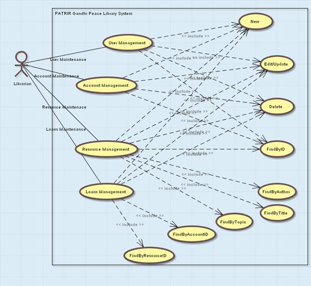
Figure The PATRIR Gandhi Peace Library Use Case Diagram
J2EE is a component-based approach to the design, development, assembly, and deployment of distributed enterprise applications. It attempts to hide the distributed character of the applications and give the impression of a single unit. The model of the platform is a multitiered one composed of components in the client tier that run on the client machine, the web tier running on the Web server, the business tier running on the J2EE server and the software that runs on the EIS (Enterprise Information System) server.
Applications built on the J2EE platform are three or four tiered like in Figure 3, but most of them are three tiered consisting of the web components, the business components and the underlying database ensuring data persistence.
Figure Multitiered applications [21]
Application clients and applets are components runing on the clients.
Java Servlets and Java Server Pages are web components runing on the server.
EJB components are business components that also run on the server.
J2EE components are assembled into a J2EE application, are verified to be well formed and in compliance with the J2EE specification, and are deployed to production in containers, where they are run and managed by the J2EE server.
The containers of J2EE components are an interface between the components and the underlying services of the J2EE server. They provide security services, transaction handling, lookup services via JNDI and remote connectivity. Figure 4 shows the server and its containers and who they serve.
Figure The J2EE server and containers [21]
As said above the J2EE application needs to be
packaged and deployed in a J2EE server. The module in which an application is
archived is called an Enterprise Archive (EAR) file, a standard Java Archive (JAR)
file with an .ear extension. An EAR file contains J2EE modules and deployment descriptors. "A deployment
descriptor is an XML document with an .xml extension that describes the deployment
settings of an application, a module, or a component. " (from J2EE Tutorial). The
modules in an .ear file are the EJB module which has the class files for the
beans and an EJB deployment descriptor in a .jar file, the web module, having
all servlets, jsps, html pages, images and a web application deployment
descriptor in a .war file, and if there exist the application client modules
packaged in a .jar file.
The Domain Model includes two submodels, the Class and Service models.
The Class Model provides the structure of an application. It is composed of classes which have attributes and operations that make up the structure of information. It is also composed of relationships between different objects that comprise an application.
This specific example requires four classes partaining to the Class Model of the Domain Model. These are User, Account, Resource and Loan. Their structure is represented in Figure 5.
Class User has attributes userID, firstName, lastName, telNo, email, address. Attribute userID is marked as a Domain Primary Unique Constraint since each User instance is a unique instance so there cannot exist two users having the same userID the same way as two people cannot have the same personal identification number.
Class Account has just an accountID which corresponds to the userID. It has an association to class User because to each user there is an account and only one.
Class Resource has attributes resourceID, the key of the resource, marked Domain Primary Unique Constraint, author, title, type, topic, and a description of the resource.
Class Loan maintains the data corresponding to a loan made by an acount on a resource of the library. Every Loan object will have a uniqueID generated automatically by the tool, fromDate and toDate to deliniate the period of the loan an reference to an account and a reference to a resource taken by their IDs. The onlyIfAvailable constraint is a Domain Unique Constraint defined on the resource reference which ensures that it is not possible for two accounts to borrow the same resource at the same time.
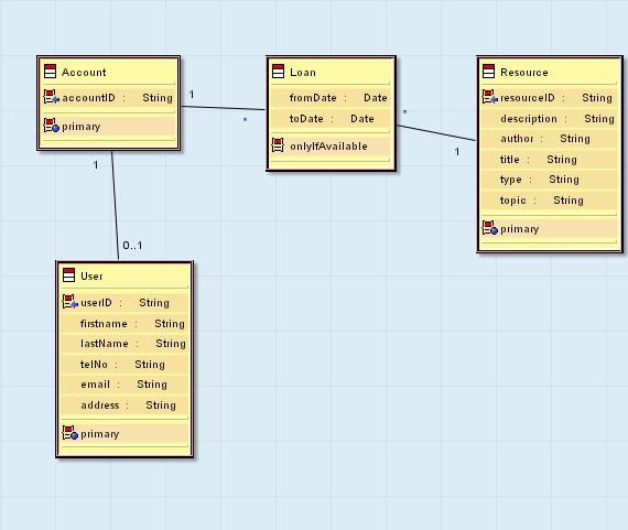
Figure The PATRIR Gandhi Peace Library Domain Model
It is possible to import an UML model into the Domain Class model. The correspondencies described in Table 1 apply. They define the pattern of transformation between the UML model to the Domain Class model.
|
Source Element |
Target Model Element |
|
Package |
ModelPackage with contentFilter |
|
Class |
DomainClass |
|
Class.Attribute name |
DomainClass.DomainAttribute |
|
Class.Relation name |
DomainClass.DomainReference |
|
Generalization |
DomainGeneralization |
|
Class.Operation |
DomainClass.DomainOperation |
|
Class.Operation.Argument name |
DomainClass.DomainOperation.DomainParameter |
|
Association |
DomainAssociation |
|
Association.AssociationEnd |
DomainAssociation.DomainAssociationEnd |
|
Class with stereotype ValueType |
DomainStructType |
|
Attributes of class with stereotype 'ValueType' |
DomainStructType.DomainField |
|
Class with stereotype EnumerationType |
DomainEnumType |
|
Attributes of a class with stereotype 'EnumerationType' |
DomainEnumType.DomainLiteral |
Table Transformation pattern from UML model to Domain Class model [19]
The Service Model is the place to specify any behavioral information regarding the structure of the application. It describes specific business rules characterizing how an application operates. The main element of the Service Model is a domain service. The Service Model is always generated or built after the Class Model in order to use existing Class Model definitions based on domain views, operations, and attributes.
For this particular application no domain services where needed to specify as the whole functionality was generated automatically by OptimalJ
The standards on which the Domain Model is based are MOF, CWM and UML, XMI defining the rules by which data are interchanged between models and model layers.
In order to obtain the Application Model from the Domain Model Technology Patterns are used. These perform a mapping between business specification and a specific technology, J2EE in this case. Technology Patterns are used to define the logical components in the DBMS, Business Logic and Presentation tiers.
Within the Application Model, submodels define other models that will be generated to implement an application. They create user interfaces, business logic, and database structures that support an application.
For our specific 3-tier application structure with integration example a DBMS model, an EJB model and a Web model are generated.
The DBMS Model represents the database structure.
The PATRIR Gandhi Peace Library DBMS model contains base tables of all business elements depicted in the Domain Model: library.xUser, library.Account, library.Resource, library.Loan. Figure 6. shows the relational data schema generated. The rules followed are:
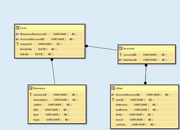
Figure The PATRIR Peace Library Relational Data Schema
Table 2 describes the correspondencies applied to the DBMS model from the Domain Class model.
Table Transformation pattern for Domain Class model to DBMS model [19] |
The Business Model contains: the Business Facade model which holds definitions for components handling the tier-to-tier communication, the Common Model containing data structures and types that are shared by application components, and the Business Logic Model, defining business requirements for a distributed application and for components allowing data processing and connection to the database.
The PATRIR Gandhi Peace Library Business Logic model contains EJB entity components for each class. The pattern generated serving attributes, component references if any of the entities are related, finder methods for the primary keys, local and remote interfaces. This all complies with the EJB simplified metamodel in Figure 7.

Figure EJB simplified metamodel [17]
To extend the searching ability in the Resource component to find by author, title and topic we had to create new finder methods using the New Finder Method Wizard, by stating just the field on which to enable the search. Due to the tool's model-to-code synchronization feature it is possible that these modifications made at the Application Model Businesslogic Module be then present in the Code Model with their specific implementation.
Table 3 describes the correspondencies between the Domain Class model to the BusinessLogic model.
|
Source Model Element |
Target Model Element |
|
ModelPackage, with contentFilter |
ModelPackage, with contentFilter |
|
DomainClass |
EJBEntityComponent EJBEntityComponent.EJBServingAttribute EJBEntityComponent.FinderMethod:
EJBEntityComponent.LocalInterface EJBEntityComponent.RemoteInterface |
|
DomainClass.DomainAttribute |
EJBEntityComponent.FinderMethod.FinderParameter, with type ApplicationDataAttribute. |
|
DomainClass.DomainOperation |
EJBEntityComponent.BusinessMethod |
|
DomainClass.DomainOperation.DomainParameter |
EJBEntityComponent.BusinessMethod.EJBComponentParameter |
|
DomainClass.DomainUniqueConstraint |
EJBEntityComponent.FinderMethod.FinderParameter, with type ApplicationKeyClass. |
|
DomainClass.DomainGeneralization |
EJBEntityComponent.EJBComponentGeneralization |
|
DomainClass.DomainReference |
EJBEntityComponent.EJBComponentReference |
Table Transformation pattern for Domain Class model to BusinessLogic model [19]
Table 4 describes the correspondencies between the BusinessLogic model and the Business Façade model.
|
Source |
Target |
|
ModelPackage with contentFilter set to |
ModelPackage with contentFilter set to |
|
DataAccessComponent EJBEntityComponent EJBSessionComponent |
BusinessFacadeComponent |
|
DataAccessComponent.DAOServingAttribute EJBComponent.EJBServingAttribute |
BusinessFacadeComponent.BusinessFacadeServingAttribute |
Table Transformation pattern for BusinessLogic model to Business Façade model [19]
Table 5 describes the correspondencies between the Domain Class model and the Application Common model.
|
Source Model Element |
Target Model Element |
|
ModelPackage, with contentFilter |
ModelPackage, with contentFilter |
|
DomainClass |
ApplicationDataSchema ApplicationDataSchema.ApplicationDataClass ApplicationKeyClass |
|
DomainClass.DomainAttribute |
ApplicationDataSchema.ApplicationDataClass.ApplicationDataAttribute |
|
DomainClass.DomainUniqueConstraint |
ApplicationKeyClass ApplicationKeyClass.ApplicationKeyAttribute |
|
DomainClass.DomainGeneralization |
ApplicationDataSchema.ApplicationDataClass.ApplicationDataClassGeneralization |
|
DomainClass.DomainReference |
ApplicationDataSchema.ApplicationDataClass.ApplicationDataReference |
|
DomainAssociation |
ApplicationDataSchema.ApplicationDataAssociation |
|
DomainAssociation.DomainAssociationEnd |
ApplicationDataAssociation.ApplicationDataAssociationEnd |
|
DomainEnumType |
ApplicationEnumType |
|
DomainEnumType.DomainLiteral |
ApplicationEnumType.ApplicationLiteral |
|
DomainStructType |
ApplicationStructType |
|
DomainStructType.DomainField |
ApplicationStructType.ApplicationField |
|
DomainAttributeConstraint |
ApplicationDataAttributeConstraint |
|
DomainCollectionType |
ApplicationCollectionType |
|
DomainAttributeConstraintException |
ApplicationAttributeConstraintException |
|
DomainAttributeConstraintException.DomainAttribute |
ApplicationAttributeConstraintException.ApplicationExceptionAttribute |
|
DomainOperationException |
ApplicationOperationException |
|
DomainOperationException.DomainAttribute |
ApplicationOperationException.ApplicationExceptionAttribute |
|
DomainUniqueConstraintException |
ApplicationKeyException |
|
DomainUniqueConstraintException.DomainAttribute |
ApplicationKeyException.ApplicationExceptionAttribute |
Table Transformation pattern for Domain Class model to Application Common model [19]
The Presentation Model is in OptimalJ a Web model representing the presentation tier of the application and containing definitions from which the user interface is generated.
The PATRIR Gandhi Peace Library Web model contains for each business class a web data schema and a web component. The web data schema has web data associations and web classes. The web component has a web serving attribute, actions, flows, web pages. All complies to the simplified Web metamodel depicted in Figure 8.
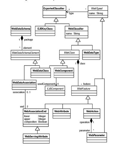
Figure Simplified Web metamodel [17]
In particular, we take the example of the Loan web component which is the most complex one. It has no serving attribute. The technology pattern created from the Domain Model:
Table 6 describes the correspondencies between components in the Domain Class model and the Web model and Table 7 the correspondencies between the data types in the two models.
|
Source |
Target |
|
ModelPackage with contentFilter set to |
ModelPackage with contentFilter set to |
|
DomainClass |
WEBComponent.
|
|
DomainClass.DomainOperation |
WEBComponent.
|
|
DomainOperation.DomainParameter |
WebOperation.WebOperationParameter |
Table Transformation pattern for Domain Class model to Web model [19]
|
Source |
Target |
|
ModelPackage with contentFilter set to |
ModelPackage with contentFilter set to |
|
DomainClass |
WEBDataSchema.
|
|
DomainClass.DomainAttribute |
WEBDataClass.WEBDataAttribute |
|
DomainAttributeConstraint You can define a domain attribute constraint at ModelPackage or DomainClass level. |
WEBDataAttributeConstraint Depending on the level defined in the class model, either at ModelPackage or at WEBDataClass level. |
|
DomainClass.DomainReference |
WEBDataClass.WEBDataReference |
|
DomainAssociation |
WEBDataSchema.WEBDataAssociation |
|
DomainAssociation.DomainAssociationEnd |
WEBDataAssociation.WEBDataAssociationEnd |
|
DomainStructType |
WEBStructType |
|
DomainStructType.DomainField |
WEBStructType.WEBField |
|
DomainEnumType |
WEBEnumType |
|
DomainEnumType.DomainLiteral |
WEBEnumType.WEBLiteral |
Table Transformation pattern for the Domain Class model to Web Data Types model [19]
Code and documentation were generated automatically using an Implementation Pattern. It complies with the Sun Mycrosystem J2EE specifications. In OptimalJ, Java, JSPs, XML, WSDL and SQL are used as specific implementation languages.
The Implementation patterns for the Business tier and the Presentation tier are depicted in the Figure 9 and Figure 10.
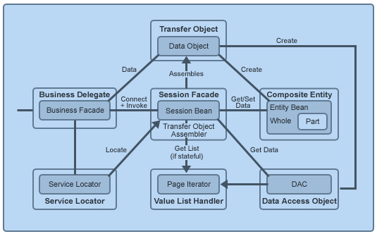
Figure Transformation pattern for Business tier in Code model [19]

Figure Transformation pattern for Presentation tier in Code model [19]
SQL scripts for creating, initializing and droping the tables, properties file, Ant build file for checking if files are available, creating jar archives, compiling.
The code is structured in modules, each having its own local directory. The generated modules are: application module, archives, business façade module, dbms module, EJB module, Web module.
The application module contains the code generated for the Application Model Common Module.
|
Package |
Java Classes |
|
x152.x111.library.application.common |
16 |
|
x152.x111.library.application.common.account |
8 |
|
x152.x111.library.application.common.user |
8 |
|
x152.x111.library.application.common.loan |
8 |
|
x152.x111.library.application.common.resource |
8 |
|
TOTAL |
48 ~ 2900 code lines |
Table Statistics: Java classes, code lines without comments and blank lines in the Common package
Figure 11 shows the structure of the x152.x111.library.application.common package.
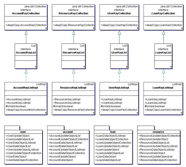
Figure Structure of x152.x111.library.application.common package
The x152.x111.library.application.common package contains a package for each domain element each having the same structure. Figure 12 shows x152.x111.library.application.common.resource package.
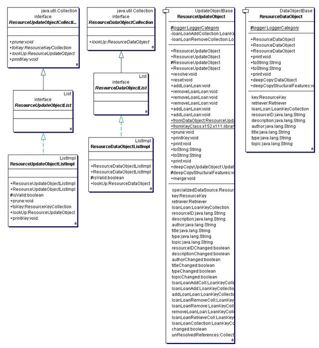
Figure Structure of x152.x111.library.application.common.resource package
The business façade module contains the code generated for the Application Model Business Façade.
|
Package |
Java Classes |
|
x152.x111.library.application.businessfacade |
4 |
|
TOTAL |
4~3700 code lines |
Table Statistics: Java classes, code lines without comments and blank lines in the BusinessFacade package
Figure 13 shows the structure generated for the x152.x111.library.application.businessfacade module.
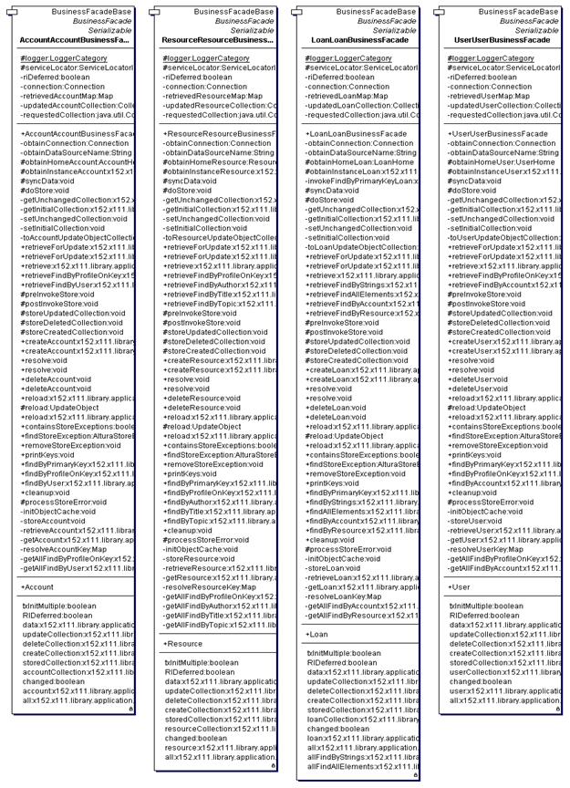
Figure Structure of x152.x111.library.application.businessfacade package
The EJB module contains the code generated from the Application Model Business Logic.
|
Package |
Java Classes |
|
x152.x111.library.application.businesslogic |
16 |
|
TOTAL |
16~3500 code lines |
Table Statistics: Java classes, code lines without comments and blank lines in the BusinessLogic package
Figure 14 shows the generated structure for the x152.x111.library.application.businesslogic package.
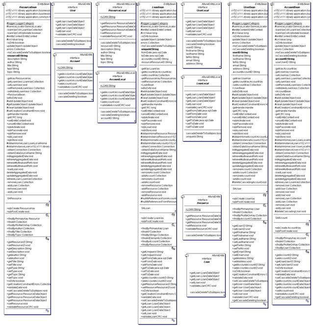
Figure Structure of x152.x111.library.application.businesslogic package
The web module contains the code generated from the Application Model Presentation Module.
|
Type |
Files |
|
jsp |
27 ~3800 code lines |
|
css |
3 |
|
images |
20 |
|
html |
1 |
|
templates (dwt) |
1 |
Table Statistics: Files in web module, number of lines in jsp files
Ant build files have also been created for every module.
Deployment descriptors have been generated for the specific deployment platforms chosen.
OptimalJ uses patterns to generate deployment descriptors, which include the SQL statements needed to query the database.
The tool allows us to choose other deployment platforms according to our own resources. This can be specified in the tool and upon code generation the specific files are created.
The application properties files can be changed according to specific needs. For example, the web site was created with default text for the different components, the site title, buttons, error messages, application version, copyright details. These could be changed from the librarywebresources.properties file.
Since the code was generated by a tool, not handwritten, the user may have difficulties in understanding the architecture of the code. The tool generates also javadoc comments for each element with descriptions of what it does. The clarity of the code is somewhat dependent on the developer's knowledge of the platform, J2EE specifically, and on the amount of time at disposal for parsing the code. For the PATRIR Gandhi Peace Library example, which is a simple example, my opinion is that the code is quite cryptic and time-consuming to understand. The extensibility, and maintainability AT CODE LEVEL suffer a great deal.
The tool also provides a compiler which checks the correctness of the generated code.
No code modifications needed to be made eventhough the tool permits it. Using the concepts of guarded blocks and free blocks the tool allows for code configuration, therefore the code can be extended. A free block is an area of code in which developers can add or modify Java code in the source files of an OptimalJ application. Free blocks are provided to give developers the ability to extend or customize OptimalJ-generated applications. Guarded blocks cannot be modified. They can be unprotected and changed but will be overwritten if code is regenerated.
In case of a behaviour change depending at which level it is situated it differs in complexity. The higher the level the easier to modify. Modifications at code level are the most complex because of the high amount of code existing and the high coupling between elements. Also because of the use of the alturadev library, the compuware framework, without some knowledge of what it brings in the code's architecture it is hard to build along it.
In order to run the application needs to be deployed on a database server and an EJB server.
Accessing server/libraryWeb/AlturaHome.do takes you to the home page of the system. Figure 15 shows the main page of the application.
The available components are: Account, Loan, Resource and User.
Figure The PATRIR Gandhi Peace Library main page
TODO - Create a new user
Step 1. Create new account instance
Step 1.1. Enter the component Maintenance Account
Step 1.2. Click New in the area beneath the top banner
Step 1.3. Introduce the data: the ID is the PIN of the user from their ID card.
!! Do not select any user ID since the user has not been created yet. !!
Step 1.4. Click OK
Step 1.5. Confirm the correctness of the data by clicking Submit. If the data are incorrect return by clicking Edit.
Step 1.5. Click Home to return to the main page.
Step 2. Create new user instance
Step 2.1. Enter the component Maintenance User
Step 2.2. Click New
Step 2.3. Introduce the data. The user ID is the same as the account ID. Now you can choose the account ID from the list by pressing Select.
Step 2.4. Click OK
Step 2.5. Confirm the correctness of the data by clicking Submit. If the data are incorrect return by clicking Edit.
Step 2.6. Click Home to return to the main page.
TODO - Create new resource
Step 1. Enter the component Maintenance Resource
Step 2. Click New
Step 3. Introduce the data.
Step 4. Click OK
Step 5. Confirm the correctness of the data by clicking Submit. If the data are incorrect return by clicking Edit.
Step 6. Click Home to return to the main page.
TODO - Borrow resource
Step 1. Enter the component Maintenance Loan
Step 2. Click New
Step 3. Insert the period of the loan in the From and To fields, then select the account ID of the borrower and the resource ID of the borrowed resource.
Step 4. Click OK
Step 5. Confirm the correctness of the data by clicking Submit. If the data are incorrect return by clicking Edit.
Step 6. Click Home to return to the main page.
OR
Step 1. Enter the component Maintenance Resource
Step 2. Find the reource to borrow.
Step 3. Enter the tab Resource.loan
Step 4. Click Add
Step 5. Complete From and To fields. Choose account ID of the borrower.
Step 6. Click OK
Step 7. Confirm the correctness of the data by clicking Submit. If the data are incorrect return by clicking Edit.
TODO - Search
Step 1. Depending on what you are searching enter the appropriate component
Search by ID
Step 1. Click the ID or part of it in the text box. (% to replace multiple characters, _ to replace one character)
Step 2. Click Browse
Search for all elements
Step 1. Click Browse with no text in the text box
OR
Step 1. Click QueryFindAllElements if available
Search for resource author (the search is case sensitive)
Step 1. In the Maintenance Resource click QueryFindByAuthor
Step 2. Enter string. (% to replace multiple characters, _ to replace one character)
Step 3. Click Browse
Search for resource title (the search is case sensitive)
Step 1. In the Maintenance Resource click QueryFindByTitle
Step 2. Enter string. (% to replace multiple characters, _ to replace one character)
Step 3. Click Browse
Search for resource topic (the search is case sensitive)
Step 1. In the Maintenance Resource click QueryFindByTopic
Step 2. Enter string. (% to replace multiple characters, _ to replace one character)
Step 3. Click Browse
TODO - Delete
Step 1. Find the object to delete.
Step 2. Click Edit
Step 3. Click Delete
Step 4. Confirm the correctness of the data by clicking Submit. If the data are incorrect return by clicking Edit.
The MDA is a young technology, but it does provide those who dare to use it some great hope for the future if enough effort is put into it from the part of the OMG, the tool vendors and the users.
OptimalJ is hardly a complete MDA tool, but it does make a good start.
Although much help is provided in the learning process of the tool by tutorials, it is still a slow process to grasp it. This can be helped if there is a good basis of knowledge in MDA, especially UML, and the specific platforms, J2EE in this case.
The PATRIR Gandhi Peace Library is a simple application. Most of its functionality was created automatically without having to put much effort in modifying the results.
Things cannot remain the same when building more complex applications.
The most important problem from my point of view is the enormous computer resources necessary to build the application, and especially the great amounts of memory needed. Appart from the tool, during the testing period, there was a Solid database engine and a JBoss with Tomcat 4.0.6. application server running. The help system which is Java based many times halted. This tool is not for the weak of the computers.
However the application works outside the tool after its deployment. Usually Internet servers having a database server and an application server have enough power to handle the rather simple application.
There are skeptics as well as those very optimistic. What lies in the future for the Model Driven Architecture depends on the actors in the technology: the OMG, tool builders, users. Time will tell. But let us see some of the issues.
The truth is, the Model Driven Architecture is a young approach. Several technical issues are not adequately addressed. Of which some of them are issues of research.
For a more widespread use in practice the stability of UML, MOF, OCL is critical.
The areas were more concern needs to be put are the methodological issues. In that sense, an agreement upon the level of abstraction of PIMs and PSMs is necessary. And also a certain border needs to be set for the point to which platforms affect application modeling concepts.
Behavioral modeling is quite a thorn in the ribs. Steps to better define behavioral elements at different levels of abstraction and means to preserve them when refining the models need to be taken.
On the issue of transformations, research in model transformation languages is imperative.
The success of MDA crucially depends on the availability of tools. These tools should support the creation and transformation of models as well as the code generation for the targeted platforms. So far, there are a few tools that support an MDA based development of software. Also most of the CASE-tool vendors have made announcements to support MDA in the future.
While OMG has defined the mapping standards between the PIM, the PSM and the resulting code, it hasn't yet defined how to implement the transformations. That has been left to the vendors currently supporting the MDA initiative. And though many MDA compliant tool vendors have implemented portions of it, few have taken the plunge to implement the MDA model completely.
The stability of the standards is also of the greatest importance in building reliable, complete MDA tools.
An issue remains the interoperability between tools. The representation of the repository should be such that more tools can understand the format. XMI is the basis, but how to use it is essential.
The next level of interoperability, at the application layer, is to provide automatically generated bridges.
Perhaps another approach to improving MDA tools out there is to have domain specific modeling tools. These should concentrate on a field of expertise and provide specific solutions for that business domain. The immediate result is that users will work with concepts known to them and the learning curve, which is quite high, can be reduced.
Working in MDA means working at a higher level of abstraction. Acquiring skills to fully take advantage of this is important. These skills include: efficient abstraction, generalization and classification capabilities, working with modeling concepts, acquiring business understanding at a higher level.
Developers in general use models informally. MDA needs formal modeling. Use today's tools. They may be incomplete, they may not solve your problems and might create new ones, they might take up a lot of your time, but how else are we to improve on them?
Develop custom generators. Work with your vendor.
Participate in the evolving standards. The feedback received from the developers is by far the most important one.
Is it worth to put effort on MDA? The benefits of such a way of software development were made obvious in the first chapters:
Increase in the level of abstraction - models as assets and not just informal documentation, focus on the business domain
Increase in productivity
Platform independence
Interoperability, simpler integration
More straightforward way of doing simulations and analysis
Automatic transformations and coding
[1] www.omg.org The OMG official site
[2] www.omg.org/mda The MDA OMG official site
[3] MDA Guide [
[4] UML 1.5 Specification [
[5] The Unified Modeling Language Reference Manual, James Rumbaugh, Ivar Jacobson, Grady Booch
[6] UML 2.0 Superstructure Specification [
[7] UML 2.0 Diagram Interchange Specification [
[8] UML 2.0 Infrastructure Specification [
[9] UML 2.0 OCL Specification [
[10] UML 2.0 Testing Profile
Specification [
[11] UML Profile for Schedulability, Performance and Time Specification
[
[12] UML Profile For Modeling Quality of Service and Fault Tolerence [
[13] MOF Specification [
[14] XMI Specification [
[15] CWM Specification [
[16]MDA Distilled: Principles of Model-Driven Architecture, Stephen J. Mellor, Kendal Scott, Axel Uhl, Dirk Weise, Addison Wesley, 2004
[17] MDA Explained: The Model Driven ArchitectureT: Practice and Promise, Anneke Kleppe, Jos Warmer, Wim Bast, Addison Wesley, 2003
[18] Object Constraint Language - Getting your Models Ready for MDA, Jos B. Warmer, Anneke G. Kleppe
[19] The OptimalJ Documentation
[20] The J2EE Specifications
[21] The J3EE Tutorial
[22] Blueprint
for code automation,
Carol Sliwa, ComputerWorld, March 2004
[23] Model Driven Architecture, JavaWorld, April 2004
[24] MDA: Nice Idea Shame about the . , Dan Haywood
[25] Tools for the Code Generation, Johanna Ambrosio, ADTMag
[26] MDA: What is in the Standard? , Johanna Ambrosio, ADTMag
[27] Quocirca's Straight Talking: Is Programming Dead?, Quocirca, www.silicon.com
[28] MDA From a Developer's Perspective, Stefan Tilkov, www.theServerSide.com
[29] Q&A MDA Today and Tomorrow, Jack Vaughan, ADTMag
[30] The Several Styles of MDA, Joaquin Miller, Lovelace Computing
[31] Model Driven Data Warehaousing, Jack Poole, Hyperion Solution Corporation
[32] CWM: Model Driven Architecture, Dr. Daniel T. Chang, IBM Database Technology Institute
[33] Model Driven Architecture and CA's Solutions, Computer Associates article
[34] The OMG Model Driven Architecture, Jon Siegel PhD., OMG
[35] MDA and System Design, Makoto Oya, Hitachi, Ltd.
[36] Model Driven Development for J2EE Utilizing a Model Driven Architecture (MDA) Approach, Productivity Analysis, The Middleware Company, June 2003
[37] MDA-based Development in Practice, Ruud Grotens, Compuware
[38] Engineering System Engineering - An Interview with Anneke Kleppe, Hans van Thiel
[39] Architectural Mismatch, David Garlan Robert Allen, John
Ockerbloom,
[40] Codagen Technologies and Model Driven Architecture, Codagen, March 2002
[41] Model Driven Architecture
Reality and Implementation, David Frankel,
[42] MDA: An Idea Whose Time Has Come, Paul Harmon, Cutter Consortium
[43] OMG Model Driven Architecture and the Application Life Cycle, Tony Mallia, CIBER Inc.
[44] Compuware's OptimalJ: Model-Driven, Pattern-based Development for Large-Scale Productivity, AberdeenGroup Profile
[45] RMA: A Pattern Based J2EE
Development Tool, Jun Chen, Master Thesis University of Waterloo,
[46] An Evaluation of Compuware's OptimalJ Professional Edition as an MDA Tool, King's College London, University of York, September 2003
|
