Introduction
O varianta completa de preamplificare plus corecctor de ton varianta HI-fi.
Preamplificatorul are o functie speciala DEAFEAT care are rolul de a desensibiliza corectia de ton ,deci in loc sa intrerupa de tot corectia pur si simplu desensibilizeaza reglajele 10dB boost and cut, and the other with a very subtle 3dB boost and cut - this will be enough (surprisingly) for very minor adjustments such as you might need for day-to-day listening.
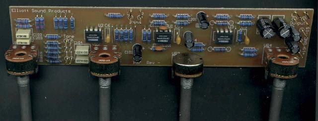 b Completed Board
The input stage is configured as shown with a gain of 2 times (6dB), and also acts as a buffer for the tone control circuit. The tone control is a basic Baxandall type, 20120e420u but the addition of R117, 118 and 119 provide flexibility and easy reconfiguration that is not available with the traditional arrangement.
R119 is the tricky part in this circuit (which is unique, by the way - I have not seen this technique used before). As shown it is 100k, and this limits the tone control range to a sensible +/-10dB. To obtain more boost and cut, R119 (and R219) may be omitted altogether. Conversely, reducing the value will give a smaller range, with about 6dB at 20Hz, and 7.5dB at 20kHz with 22k.
 Figure 1 - Input
and Tone Controls
Figure 1 - Input
and Tone Controls
The tone control (and overall) performance is shown in Figure 2 (10% steps of the pots), and it can be seen that the midrange is barely affected. This is in contrast to the majority of designs, where the controls are centred on 1kHz, and there is a very audible effect in the midrange frequencies. For those who absolutely do not want to use tone controls, I suggest the DoZ preamp (Project 37) or Project 88 - both were designed with no tone controls and are more in the line of true minimalist designs.
Figure
2 - Frequency Response (SW1 Open)
By contrast, Figure 3 shows the tone control range when SW1 is closed. This also means that when the controls are centred, any minor deviation (due to pot tolerances) is minimal, and response is completely flat (within 0.1dB). As you can see, the variation is much smaller, and it is probable that this setting will be the only one used most of the time.
Figure
3 - Frequency Response (SW1 Closed)
In Figure 3, the curves are shown for maximum, 75%, 50% 25% and minimum settings of the tone controls. The treble response is more pronounced than bass, but is still limited to a maximum of +/-3dB at 20kHz. Overall, The circuit has excellent flexibility, and will suit normal "rumpus room" duties just as readily as it will suit the listening room. Balance, volume and output stages are shown below ...
 Figure
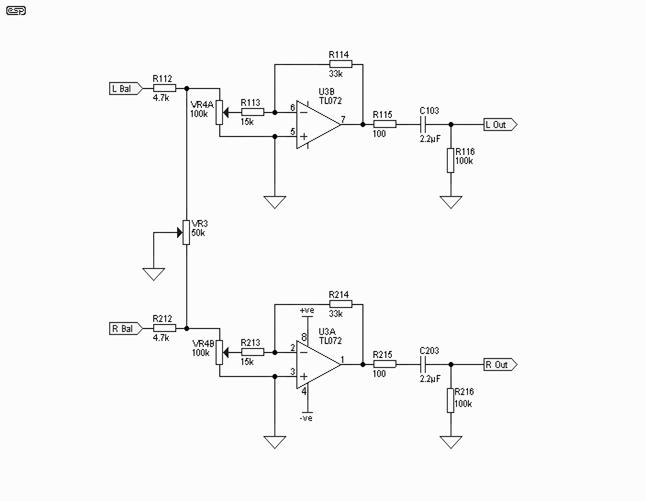
4 - Balance, Volume and Output Stage
Figure
4 - Balance, Volume and Output Stage
The balance control is deliberately designed to have very little effect around the central position, as this makes precise positioning much easier. The volume control uses a linear pot, and overall system gain is about 0dB with the pot in the "12 o'clock" position. Maximum gain is 13dB, and the volume control uses a modified version of Project 1's "Better Volume Control" to obtain a log response. Output impedance is 100 ohms, and using the suggested 2.2uF polyester cap, the preamp will drive a 22k load with overall response as shown in figures 2 and 3. Low frequency cutoff is about 3Hz with a nominal 22k load. A higher value may be used for C103/203 if desired, but it is expected that the value shown will be quite sufficient for all normal power amplifiers.
The final stage is inverting - this is to correct for the inversion in the tone controls, and brings the overall phase back to normal. Again, this stage runs with a nominal gain of 6dB, although this varies as the volume pot is adjusted. Lowest noise is obtained at a middle setting of VR4 - the general area where the pot will be used the most.
Where it is found that the gain is excessive, R114/214 can be reduced in value - with 15k resistors, gain of this stage will be reduced to unity (probably too low), and a sensible compromise would be 22k. It depends on the input sensivity of the power amplifier of course, so this is left up to the reader to determine after some initial tests. Additional holes are provided in the PCB to allow you to reduce the gain without having to remove the existing resistors should that be found necessary.
ceramic 100nF caps and 10uF electros are used for RF stability as usual. These are essential, and especially so where high speed opamps are used.
Figure
5 - Supply Bypass Components
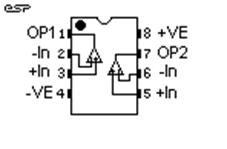
TL072 opamps, OPA2134
All resistors should be metal film, and
preferably 1% tolerance for best channel matching and noise performance.
Likewise, the capacitors for the tone controls should be matched as closely as possible, using a capacitance
meter. The pots are all linear, and for the PCB, you will need PCB mount 16mm
pots, as these are reasonably common everywhere.
Power should be +/-12 to +/-15V, with the higher voltage giving the best headroom
|
