C45/M50/MT50/A50
intermediate repair level
Generic Repair Documentation
Table of Content
Introduction
I/O Connector (Lumberg)
Battery Connector
Display Connector
Antenna Connector
Card Reader
Keypad LEDs
Display LEDs
C45/M50/MT50/A50 product family consists of 6 different dualband handsets (GSM-900 and GSM-1800), which can easily be distinguished from the second block of the partnumber printed on the IMEI label.
Partnumber on IMEI label:
C45: S30880-S5100-#xxx
, while # may be any letter (A-Z 535q1622f ) and xxx may be any number from 100, 101, 102....
2118: S30880-S5100-#xxx (China Version C45)
, while # may be any letter (A-Z 535q1622f ) and xxx may be any number from 800, 801, 802....
M50 S30880-S5150-#xxx
, while # may be any letter (A-Z 535q1622f ) and xxx may be any number from 100, 101, 1 02....
MT50 S30880-S5120-#xxx
, while # may be any letter (A-Z 535q1622f ) and xxx may be any number from 100, 101, 1 02....
3118: S30880-S5150-#xxx (China Version M50)
, while # may be any letter (A-Z 535q1622f ) and xxx may be any number from 800, 801, 802....
A50: S30880-S5110-#xxx
, while # may be any letter (A-Z 535q1622f ) and xxx may be any number from 800, 801, 802....
This manual is intended to help you carry out repairs on level 2.5, meaning limited component repairs. Failure highlights are documented and should be repaired in the local workshops.
It must be noted that all repairs have to be carried out in an environment set up according to the ESD (Electrostatic Discharge Sensitive Devices) regulations defined in international standards.
- Charging problems.
- Problems with external loudspeaker or microphone
when using a car kit.
- Problems with accessories connected at the I/O -
connector.
- Problems with SW booting
This fault cannot be detected with a GSM-Tester
Mandatory
Repair
Optional
Not Yet Defined
Visually check the bottom connector. Watch for dry joints:
Use hot air blower remove defective I/O connector.
Avoid excessive heat!
Watch surrounding components!
Resolder new I/O connector afterwards.
Not possible!
Retest handset after repair.
I/O Connector C45/M50/MT50/A50
Part-Number: L36334-Z93-C262
Hot Air Blower
Soldering Iron
None
Desolder Wick / Braid
Solder
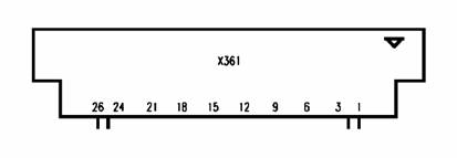
Figure 1: C45/M50/MT50/A50 board I/O connector
![]()

Figure 2: C45/M50/MT50/A50 I/O connector placement (top view)
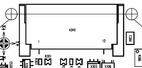
Table 1: C45/M50/MT50/A50 Bottom Connector Pin Description
|
Pin |
Name |
IN/OUT |
Notes |
|
GND | |||
|
SB |
I/O |
Charger coding and charger control. |
|
|
POWER |
I |
Charging Current |
|
|
FBatt+ |
O |
Power supply for accessories. |
|
|
TX |
O |
Serial interface |
|
|
RX |
I |
Serial interface |
|
|
ZUB_CLK |
I/O |
Clock line for accessory bus Use as DTC In data operation |
|
|
ZUB_DATA |
I/O |
Data line for accessory bus. Use as CTS in data operation |
|
|
GND_MIC |
For external microphone |
||
|
MICP2 |
I |
External microphone |
|
|
EPP2 |
O |
External loudspeaker |
|
|
EPP1 |
O |
External loudspeaker |
Error message "WRONG BATTERY" on display.
This fault cannot be detected with a GSM-Tester.
Mandatory
Repair
Optional
Not Yet Defined
Visually check the status of the
Mechanically check the opening / closing mechanism.
Use hot air
blower remove defective
Avoid excessive heat!
Watch surrounding components!
Resolder new
Not possible!
Retest handset after repair.
Part-Number: L36158-A54-C215
Hot Air Blower
Soldering Iron
None
Desolder Wick / Braid
Soldering Iron
![]()
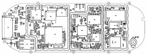
Figure 1: C45/M50/MT50/A50 board
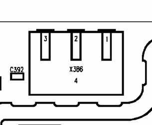
Figure 2: C45/M50/MT50/A50
Display problems, like missing lines or columns on the LCD or display contrast problems.
Display tests failed.
Mandatory
Repair
Optional
Not Yet Defined
Visually check the status of the Display connector. Watch for oxidation and dry solder joints.
Mechanically check the opening / closing mechanism.
Use hot air blower remove defective Display connector.
Avoid excessive heat!
Watch surrounding components!
Resolder new Display connector afterwards.
Not possible!
Retest handset after repair.
Part-Number: L36195-Z26-C629
Hot Air Blower
Soldering Iron
None
Desolder Wick / Braid
Soldering Iron
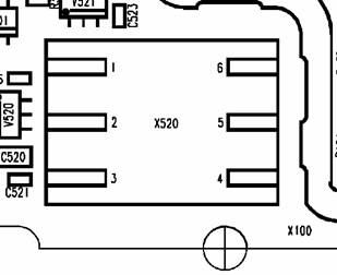
Figure 1: C45/M50/MT50/A50 board Display connector

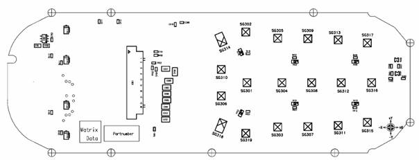
Figure 2: C45/M50/MT50/A50 Display connector placement (top view)
Pin1 Pin 26
![]()
![]()
Network Search
No location update possible
Output power problems on the external and internal antenna
No location update possible
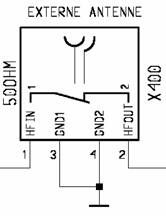
The Antenna Connector is a mechanical switch operated by the RF plug of a car kit.
 Normally
the RF signal goes to and comes from the internal antenna. Whenever an RF plug
is plugged into the antenna connector the connection to the internal antenna is
opened and the connection to the external antenna socket is made. When the
antenna connector is blocked without RF plug the connection to the internal
antenna is also opened. See drawing below.
Normally
the RF signal goes to and comes from the internal antenna. Whenever an RF plug
is plugged into the antenna connector the connection to the internal antenna is
opened and the connection to the external antenna socket is made. When the
antenna connector is blocked without RF plug the connection to the internal
antenna is also opened. See drawing below.
From Power Amplifier/ To/From Internal Antenna
![]()
To Receiver
Mandatory
Repair
Optional
Not Yet Defined
Check the output power of the handset with the LSO test program. Especially watch the external antenna power!
Use hot air to remove defective antenna connector.
Avoid excessive heat!
Watch surrounding components!!
Resolder new module afterwards
Not possible!
Retest handset after repair.
Antenna Connector C45/M50/MT50/A50
Part-Number: L36334-Z93-C261
Hot Air Blower
Soldering Iron
None
Desolder Wick / Braid
Soldering Iron
Figure 1: C45/M50/MT50/A50 board Antenna connector

Figure 2: C45/M50/MT50/A50 Antenna connector placement (top view)
Handset does not accept SIM.
This fault cannot be detected with a GSM-Tester
Mandatory
Repair
Optional
Not Yet Defined
Visually check the Card Reader. Watch for dry joints:
Use soldering iron to remove defective component.
Avoid excessive heat!
Watch surrounding components!
Resolder new Card Reader afterwards.
Not possible!
Retest handset after repair.
Card Reader C45/M50/MT50/A50
Part-Number: L36158-A54-C211
Hot Air Blower
Soldering Iron
None
Desolder Wick / Braid
Soldering Iron
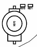
Figure 1: C45/M50/MT50/A50 board Card Reader site

Figure 2: C45/M50/MT50/A50 Card Reader placement (top view)
Keyboard Illumination does not work.
This fault cannot be detected with a GSM-Tester
Mandatory
Repair
Optional
Not Yet Defined
Use the diode test function of a multimeter to check the status of the diode. The typical voltage drop on the diode is 1.7V when testing the diode function with the multimeter
Use soldering iron to remove defective diode.
Avoid excessive heat!
Watch surrounding components!!
Resolder new diode afterwards.
Not possible!
Retest handset after repair.
LEDs C45/M50/MT50 Amber /A50
Part-Number: L36840-L2056-D670
Hot Air Blower
Soldering Iron
None
Desolder Wick / Braid
Soldering Iron
Figure 1: C45/M50/MT50/A50 board keyboard LEDs side
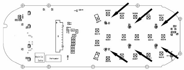
Figure 2: C45/M50/MT50/A50 LEDs placement (top view)
Display Illumination does not work.
This fault cannot be detected with a GSM-Tester
Mandatory
Repair
Optional
Not Yet Defined
Use the diode test function of a multimeter to check the status of the diode. The typical voltage drop on the diode is 1.7V when testing the diode function with the multimeter
Use soldering iron to remove defective diode.
Avoid excessive heat!
Watch surrounding components!!
Resolder new diode afterwards.
Not possible!
Retest handset after repair.
LEDs C45/M50/MT50 Amber /A50
Part-Number: L36840-L2055-D670
LEDs M50/MT50 Blue
Part-Number: L36197-F5005-F782
Hot Air Blower
Soldering Iron
None
Desolder Wick / Braid
Soldering Iron
Figure 1: C45/M50/MT50/A50 board keyboard LEDs side
 Figure
2: C45/M50/MT50/A50 LEDs placement (top view)
Figure
2: C45/M50/MT50/A50 LEDs placement (top view)
|
